The use of composite structures is increasingly present in civil construction works. Steel-concrete composite beams, particularly, are structures consisting of two materials, a steel section located mainly in the tension region and a concrete section, located in the compression cross sectional area , both connected by metal devices known as shear connectors. The main functions of these connectors are to allow for the joint behavior of the beam-slab, to restrict longitudinal slipping and uplifting at the elements interface and to take shear forces. This paper presents 3D numerical models of steel-concrete composite beams to simulate their structural behavior, with emphasis on the beam-slab interface. Simulations were car-ried out using version 10.0 ANSYS code, based on the Finite Element Method. The results obtained were compared with those provided either by Standards or found in the literature, and such comparison demonstrated that the numerical approach followed is a valid tool in analyzing steel-concrete composite beams performance.
Keywords: composite beams, shear connectors, numerical modeling, inite element (EF).
A utilização de estruturas mistas está cada vez mais presente nas obras de Engenharia Civil. As vigas mistas, em particular, são estruturas compostas por dois materiais, um peril metálico, situado em região predominantemente tracionada, e uma seção de concreto, situada em região predominantemente comprimida, ligados entre si através de dispositivos metálicos denominados de conectores de cisalhamento. As funções prin-cipais dos conectores são: permitir o trabalho solidário da laje-viga, restringir o escorregamento longitudinal e o deslocamento vertical na interface dos elementos e, absorver forças de cisalhamento. Nesse contexto, apresentam-se neste trabalho, modelos numéricos tridimensionais de vigas mistas aço-concreto, com a inalidade de simular o seu comportamento estrutural, enfatizando a interface laje-viga. As simulações foram feitas através do software ANSYS versão 10.0, que tem como base o Método de Elementos Finitos. Os resultados obtidos foram comparados com os previstos por norma e com referências encontradas na revisão bibliográica, veriicando-se que a modelagem numérica é uma ferramenta válida para a análise de vigas mistas aço-concreto.
Palavras-chave: vigas mistas, conectores de cisalhamento, modelagem numérica, elementos initos (EF) .
Numerical modeling of steel-concrete composite beams
Modelagem numérica de vigas mistas aço-concreto
L. R. MARCONCIN a
R. D. MACHADO b
M. A. MARINO c
a L. R. MARCONCIN. Universidade Federal do Paraná, Centro de Estudos de Engenharia Civil. [email protected]. Prof. Inaldo Ayres Vieira - Centro Politécnico. Jardim das Américas. Caixa Postal 19.011 – CEP: 81.531-980 – Curitiba, PR;
b R. D. MACHADO. Universidade Federal do Paraná, Centro de Estudos de Engenharia Civil. [email protected]. Prof. Inaldo Ayres Vieira - Centro Politécnico. Jardim das Américas. Caixa Postal 19.011 – CEP: 81.531-980 – Curitiba, PR;
c M. A. MARINO. Universidade Federal do Paraná, Centro de Estudos de Engenharia Civil. [email protected]. Prof. Inaldo Ayres Vieira - Centro Politécnico. Jardim das Américas. Caixa Postal 19.011 – CEP: 81.531-980 – Curitiba, PR.
Received: 03 Oct 2009 • Accepted: 03 Sep 2010 • Available Online: 17 Dec 2010
Abstract
Resumo
1. Introduction
1.1 General aspects
The composite steel-concrete systems were irst used in the mid-dle of the last century. They involve the joint work of concrete ele-ments and steel sections, interacting mechanically by means of connectors, dents or bumps, either by friction or adhesion. Generally, composite beams are made out of a combination of a steel section (commonly “I” shaped), located on predominantly ten -sioned region, with a concrete slab, positioned in predominantly compressed area. The mechanical binding is provided by metal devices called shear connectors. The main functions of the shear connectors are to allow for the joint work of the slab-beam new ma-terial [10], restricting longitudinal slip and vertical displacements of the interface elements, and to take shear forces [3].
By combining steel and concrete this way, it is possible to obtain the advantages of both materials working together [8]. Therefore, from the materials strength point of view, it is possible to take ad-vantage of the steel section to take tension stresses and of the concrete in order to withstand compressive stresses [10]. This combination results in high stiffness and smaller structural sections [10], lighter foundation design, gains in materials performance and reduced costs. In addition, composite systems allow for the occa -sional elimination of formwork and shoring, and may reduce steel protection against ire and corrosion, due to the presence and ad -equate behavior of concrete in the system.
In Brazil, the irst structures making use of composite systems were built in the 50s. However, in the last twenty years, a growth in steel production [4], as noticed by a bigger supply of steel sections in the domestic market, caused composite systems to increase drastically.
Having this picture in mind, this article focus numerical analy-sis of composite beams. The main idea is to make use of the computer program ANSYS [1], which is based on the Finite Element Method.
1.2 Purpose
The objective is to verify the inluence of the amount, diameter and height of shear connectors in composite beams. These veriica-tions were made by means of the analysis of longitudinal slip in the slab-beam interface, the vertical displacement at mid-span and the bearing capacity of composite beams. The results were compared to those provided by standards and to other data found in the con-sulted literature.
2. Numerical modeling
This paper uses models for composite beams, particularly the “A3”, extracted from experimental tests [6] and numerical applications [11]. The tested model here presented, developed by a researcher [11], uses the same geometry, parameters, material properties and no-menclature of the composite beam deined in the referenced work. Despite the methodology applied here is broad and general, the “A3” model simulated in this paper refers solely to the simply sup -ported composite beam (Figure 1). It was deined as having solid web, full interaction between the slab and the steel section provid-ed a by number of shear connectors calculatprovid-ed to prevent slipping
between the surfaces, lat concrete slab with two way reinforce -ment (transverse and longitudinal), shear connectors with pin-type head (stud bolt) and subjected to a point load in the mid span. The model was based on the inite element method, also used by other researchers [7], [10], [11] [14] and [15].
The model implementation started with the deinition of the ge-ometry of the composite beam (Figure 1). Secondly, inite el -ements available in the ANSYS [1] computer program library, were chosen to represent the composite materials. Thirdly, the properties and constitutive relations of the materials involved were introduced. Finally, the mesh, couplings and linkages be-tween the elements were added, taking into consideration the symmetry condition and the consequent restriction of degrees of freedom, and also the beam support conditions and the ap-plied load.
The irst simulation was done vis-à-vis the unique characteristic of the A3 beam, to validate the model. Then, to analyze the connec-tors inluence on the structural behavior of the composite beam, several alternatives for connectors were analyzed, with diameters ranging from 16 mm, 19 mm and 22 mm and heights from 76 mm, 88 mm and 102 mm. Lastly, the number of connectors recom -mended by the standard [2] was used, following the calculation procedure available in [12].
2.1 Finite elements
The deinition of the proposed numerical model was made by using inite elements available in the ANSYS code default library [1]. The three-dimensional elements SOLID 65 were adopted to dis -cretize the concrete slab, which are also able to simulate crack-ing behavior of the concrete under tension (in three orthogonal directions) and crushing in compression, to evaluate the material non-linearity and also to enable the inclusion of reinforcement (re -inforcement bars scattered in the concrete region).
L. R. MARCONCIN | R. D. MACHADO | M. A. MARINO
es’ plasticity criterion, based on the relationship between uniaxial tensions and their respective plastic deformations, as shown in the stress-strain diagram in Figure 4.
For the concrete slab, the constitutive tension relationship followed the CONCRETE model, provided by ANSYS [1], which is based on the Willam-Warnke solution and allows for the material crack-ing. This model was also used in [7] and [15]. For the concrete in compression, on the other hand, von Mises’ laminating criterion was adopted. The model represents the behavior of a multilinear isotropic concrete hardening, given by the stress-strain diagram in Figure 5.
The solution for the contact between the concrete slab, the steel section and the connectors made use of the Pure Lagrange Multi-the material and show linear deformation on Multi-the plane in which it
is present.
The modeling of the shear connectors was done by the BEAM 189 elements, which allow for the coniguration of the cross section, enable consideration of the non-linearity of the material and in-clude bending stresses.
The TARGE 170 and CONTA 173 elements were used to repre-sent the contact slab-beam interface. These elements are able to simulate the existence of pressure between them when there is contact, and separation between them when there is not. The two material contact also take into account friction and cohesion be-tween the parties.
2.2 Materials properties
The characteristics of the “A3” beam and the real properties of materials are presented in Table 1. It is noteworthy mentioning that this study also considered other conigurations for the connectors, as number, height and diameter.
2.3 Constitutive relations
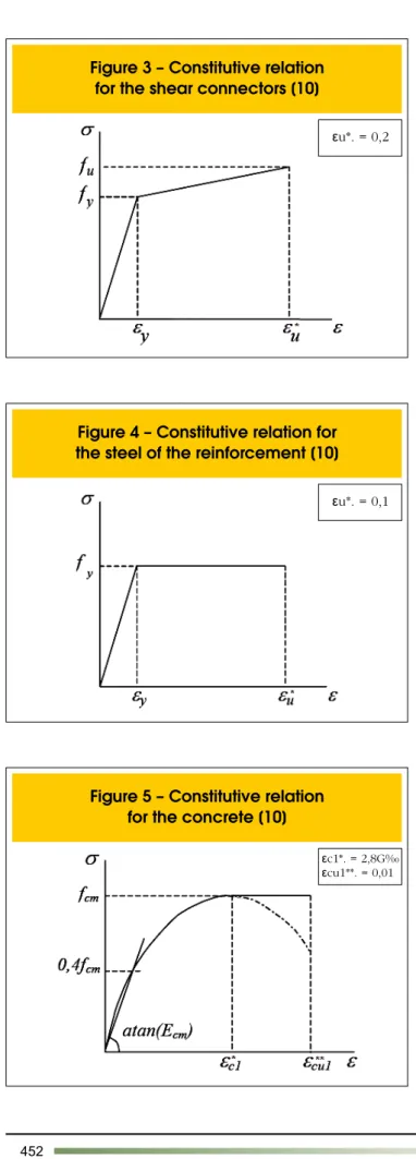
It was considered that the steel section has a multilinear elastic-plastic constitutive relationship with an isotropic hardening con-sideration, associated with the von Mises’ plasticity criterion. The stress-strain curve followed the constitutive model presented in [9] and it was used in [15] and [7], as shown in Figure 2.
Mis-plier method, also provided by ANSYS [1]. This method assumes that there is no interpenetration between the two materials when the contact is closed and also that the slip is null, as long as it does not reach the shear stress limit [11]. The parameters that deine if the contact is open or closed are set by FTOLN, which refers to a minimum value of penetration as to presume that the contact is closed and TNOP, which refers to a minimum value of normal tension to the contact surface, so that the status changes to open. The absolute value adopted for FTOLN was -0.01 cm. For the TNOP the value adopted was 0.18 kN/cm2. The established
value of the friction coeficient between steel and concrete was 0.4 and, for cohesion, an estimated number of 0.18 kN/cm2 was taken
from average values of adhesion tension related to the initial slip of the interface.
2.4 Finite elements mesh
The model designed for the numerical analysis was deined by four types of elements that form the concrete slab with added re-inforcements, such as steel beam, shear connectors and the pair of contact at the slab-beam interface. The elements were estab-lished separately, but the nodes were one by one coupled on the interface between them.
The inite element mesh developed for all elements followed the same methodology and degree of reinement presented in [11]. Figure 6 shows the inite element mesh for the components cited, where (a) corresponds to the concrete slab, (b) to the steel beam, (c) to the shear connectors and (d) to the pair.
2.5 Couplings and linkages
The couplings connecting the elements consider the nodes su-perposition, with the degrees of freedom adapted, as illustrated in Figure 7.
The contact between the slab and the beam was established by the CONTA 173 elements, attached to the section web, and TARGE 170, attached to the inferior surface of the slab. The beam-connector link was considered as a clamped metal pin in the steel section, with rotations and translations made compatible. On the slab-connector interface, translational referring to the X and Z axis were also made compatible and, at the node below the pin head, there was a consideration of coupling in the Y direction to repre-sent the mechanical anchoring between the head of the connector and the concrete slab.
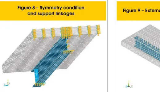
Attempting to reproduce a movable type support, the degrees of freedom related to the translation in X and the rotation in Z were not restricted at referred nodes of the composite beam support. At the nodes of the central section of the composite beam, a symme-try condition was applied, also provided by ANSYS [1] and, con-sequently, a restriction of degrees of freedom. Figure 8 shows the symmetry condition, the binding of the composite support beam in detail, and also the coupling between the materials.
time it would start acting as a composite beam, the structure would already be deformed.
In this context, to simulate the loading application in beam A3, the Birth & Death’s technique, available in ANSYS [1], was adopted. This technique, which allows for elements activation and inacti-vation of a discretized mesh, consists of the multiplication of the value of the inactivated entity in the stiffness matrix and a reduction factor, which practically blocks the effects of the results of such en-tity. In this paper the adopted reduction factor was 10-6. Firstly, the
concrete slab and the shear connectors were inactivated and the structure dead weight was applied to the steel section. Secondly, the concrete slab was activated and the applied load was used in regard of the solidarity slab-beam work. The structure dead weight was inputted into the modeling according to the unit weight of the materials, which were: 24 kN/m³ for the concrete and 77 kN/m³ for the steel girder, connectors and reinforcements. The applied load was incrementally and monotonically included immediately after the action of the dead weight of the composite beam. Although concentrated in the middle of the span, the load was considered
as spread throughout a small area, applied at the nodes of the upper surface of the concrete slab, centered on the axis of the beam, according to the experimental model presented in [6]. Both the structure dead load and the applied load were included incre-mentally in the model to take into account the nonlinear behavior of the materials that form the composite beam.
Figure 9 shows the composite beam with an applied load concen-trated on the mid-span.
3. Results and discussions
L. R. MARCONCIN | R. D. MACHADO | M. A. MARINO
Figure 10 shows that, under the elastic range, results for the com-posite beams are similar for both the experimental and numerical models. In the nonlinear range, the limit load of the simulated nu -merical model was 7.5% higher than the one for the experimental model, presented in [6], and 8.5% higher than the one for the nu -merical model, in [11].
Regarding the vertical displacement at the center of the span of the beams in the limit load, the value of the numerical model is 27% lower than the experimental one exposed in [6]. This suggests a more rigid behavior of the model developed in this work.
The analyzed slip, on the other hand, did not show the same be-havior. At the limit load, the experimental [6] and numerical [11] model presented similar sliding, while the experimental model re-sulted in a sliding 20% lower.
Thus, it can be inferred that it is possible to represent numerically experimental models. It is likely that the differences found between the models are due to numerical instability, stemming from experi-mental models calibration because of the adopted parameters.
3.1 Inluence of connectors
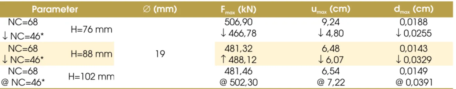
Table 2 displays the result of the inluence of the connector height (H) in the limit load (Fmax), in the vertical displacement at mid-span
(umax) and in the average relative longitudinal slip (dmax) (between
the slab and the steel section), at the end of the beam for the sec-ond stage of simulations. Maximum loading occurs for the connec-tor with H=76mm. This solution was also the one which showed greater vertical displacement and longitudinal sliding; this suggests a more ductile behavior than others. Thus, it appears that increas-ing the height of the connector does not necessarily increases the load limit, the vertical displacement or the longitudinal sliding. It is presented in Table 3 the result of the inluence of the diameter of the connector (Ø) in the limit load (Fmax), in the vertical
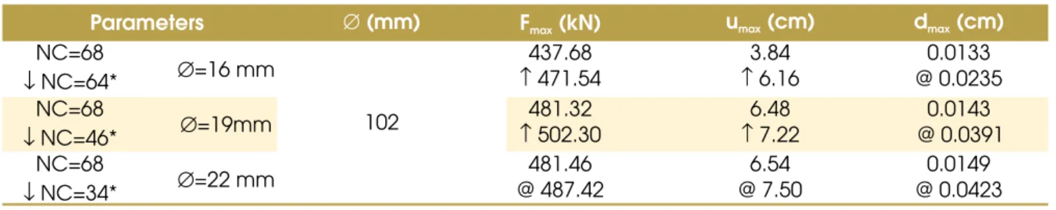
displace-ment at mid-span (umax) and in the average relative longitudinal
slip (dmax) (between the slab and the proile steel), at the end of
the beam.
Table 3 shows that increasing the diameter of the connector in-creases the limit load, the vertical displacement and the longi-tudinal slip, whose highest value corresponds to the connector Ø=22 mm.
Table 4 shows the comparative result for the second and the third steps of the simulations for the inluence of the numbers of connec -tors (NC), with different heights (H), in the limit load (Fmax), in the
vertical displacement at mid-span (umax) and in the average relative
longitudinal slip (dmax) (between the slab and the steel proile), at
It may be noted from Table 4 that reducing the number of connec -tors (↓NC) results in an ampliication (↑) of the longitudinal slip but, not necessarily, in the decrease (↓) of the maximum force and the increase of the vertical displacement.
Table 5 shows the comparative results of the second and third
steps of the simulation for the inluence of the number of connec -tors (NC), with different diameters (Ø), in the load limit (Fmax), in the
vertical displacement at mid-span (umax) and in the average relative
longitudinal slip (dmax) (between the slab and the steel section), at
L. R. MARCONCIN | R. D. MACHADO | M. A. MARINO
It is possible to infer from Table 5 that the decrease (↓) of the number of connectors (NC) implies an increase (↑) of the verti-cal displacement and of the longitudinal sliding, but not
neces-sarily, in a reduction (↓) of the maximal force.
-lution of vertical displacements at mid-span (a) and average rela -tive longitudinal sliding (between the slab and the steel section), at the end of the composite beam (b) with the total force applied to the mixed system.
Figure 11 shows the comparative graphics of force versus dis-placement (a) and force versus slip (b) for beams with connectors 19 mm in diameter, and Figure 12 shows the comparative graphics of force versus displacement (a) and force versus slip (b) of com-posite beams with connectors 102 mm in height.
Figures 11 and 12 show that the behavior of composite beams in the elastic range were similar for all connectors, regardless their number, diameter and height. However, in the nonlinear range, the reduction in the number of connectors implies an increasing of the longitudinal slip and it has no preponderant inluence on the force and on the vertical displacement.
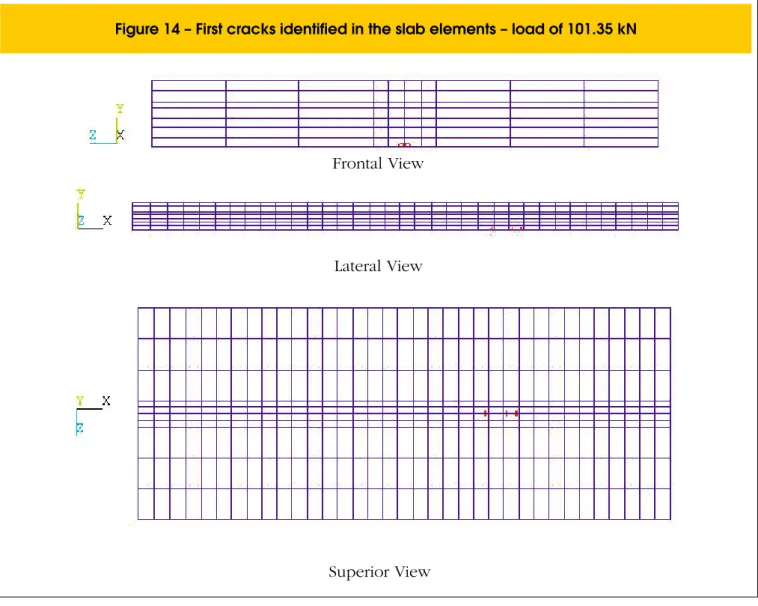
Figures 14, 15 and 16 show cracks in the elements of the concrete slab of the composite beam with connectors 19 mm in diameter and 102 mm in height.
According to the settings of ANSYS, the irst crack occurring in the element is represented by a red circle, the second by a green circle and the third by a blue circle. These circles appear at the
centroid of each element and are inclined according to the plane that contains the crack.
The cracking modes in the slab are due to a strength and stiff-ness reduction of the concrete in the triaxial compression zone as a consequence of concrete cracking caused by the connector, when it applies a concentrated force in the slab [10]. In Figure 13 it is possible to check the three modes of cracking occurring in the slab [13].
Figure 14 shows that the irst cracks in the concrete slab elements were identiied for an applied load equal to 101.35 kN.
Figure 15 shows the irst cracks by shearing in the concrete slab el -ements, which were lagged for a loading level equal to 151.45 kN. Besides these cracks, it is possible to observe transverse cracks (Z direction) in the middle of the span of this igure.
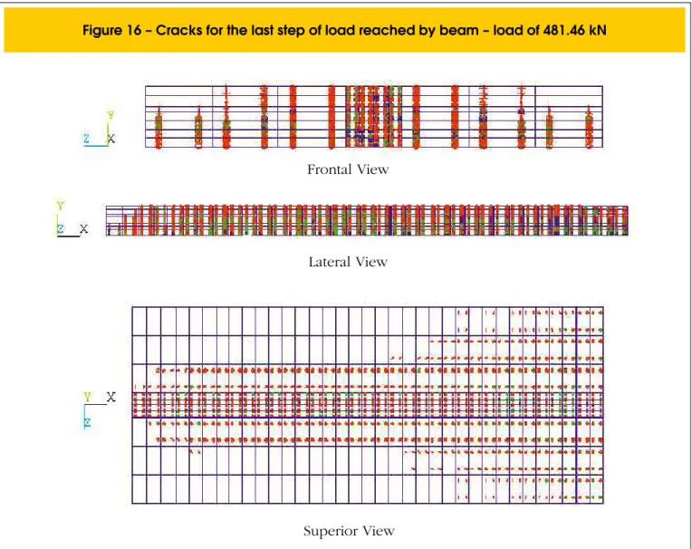
The cracking of the concrete slab for the loading last step (481.46 kN) is shown in Figure 16.
verse cracks identiied (Z direction) in the slab-beam interface, from tensile longitudinal stresses. It was also observed, for this load level, the presence of longitudinal cracks (X direction), that initially occur in front of the connector and then behind it. These are shearing cracks. It was also possible to identify shear cracking, inclined 45 degrees in the elements of the concrete slab. Figure 16 shows the cracking state of the slab for a 481.46 kN load, which corresponds to the loading last step achieved in the numerical simulation.
Tables 6 and 7 present the results obtained in the third stage of the simulation and in the calculation of composite beams, according to standard recommendations [2], whose procedure is in [12] for the limit load (Fmax) and the vertical displacement mid-span (umax).
It is noteworthy that the number of shear connectors and the oth -er paramet-ers (force, displacement) w-ere deined in t-erms of the lower resistance between the concrete slab and the steel section. That is, according to standard recommendations [2], the values ob-tained for the vertical displacements and forces are independent of the diameter and height of the shear connectors; because, in this case, since the composite section of the adopted beam was the same for all simulated models and since the concrete resistance to
rupture is lower than the connector capacity to resist shearing, the force and displacement are the same for both models.
Table 6 refers to results of composite beams with 19 mm diameter (Ø) connectors as a function of a variation in height (H), and Table 7 shows results of composite beams with 102 mm high (H) connec -tors versus the variation in diameter (Ø).
It can be seen from Tables 6 and 7 that the maximum force cal -culated by the NBR 8800 [2] is conservative, because it presents lower values than those obtained in the numerical simulation. The vertical displacements were much higher than those found in nu-merical simulations, indicating a more rigid behavior of simulated models and a more ductile performance of the calculated ones.
4. Conclusions
L. R. MARCONCIN | R. D. MACHADO | M. A. MARINO
In the second stage of simulations, three diameters and three height values of for shear connectors were used, and it was observed that increasing the height of the connector does not necessarily increase the load limit, the vertical displacement and the longitudinal slip, but increasing the diameter of the connector increases the limit load, the vertical displacement and the longitudinal slipping in the slab-beam interface. In this stage it was still possible to visualize and analyze the state of cracking of the concrete slab due to the use of the SOLID 65 element.
In the third stage of simulations, there was a variation in the amount of shear connectors, while maintaining, for the adopted model, the same material properties and diameters and height variations of the second testing stage. The objective was to verify the inluence of the number of connectors in the models by comparing results with those obtained in the second round of simulations, and evaluate the correspondence of numerical re-sults to the standard one. Thus, the number of connectors was chosen in accordance with NBR 8800 [2] recommendations, whose calculations are presented in [12]. Therefore, by compar-ing the results obtained in the second and third stages, it was found that, in the elastic range, the results are similar regardless of quantity, diameter and height of the connectors. However, in the nonlinear range, the reduction in the number of connectors implies increase in longitudinal slip and has no preponderant inluence on the strength and on the vertical displacement. In comparing the values obtained from simulations to those calculated according to standard recommendations [2], it was noted that standard recommendations are conservative, be-cause they provide lower values than those obtained in the simulations.
5. References
[01] ANSYS. Version 10.0 Documentation. ANSYS, Inc. [02] ASSOCIAÇÃO BRASILEIRA DE NORMAS
TÉCNICAS. NBR 8800 – Projeto de estruturas de aço e de estruturas mistas de aço e concreto de edifícios, Rio de Janeiro, 2008.
[03] ALVA, G. M. S.; MALITE, M. Comportamento estrutural e dimensionamento de elementos mistos aço-concreto. Publicação Interna: Cadernos de Engenharia de Estruturas - Escola de Engenharia de São Carlos, Universidade de São Paulo, vol. 7, n. 25, 2005, p. 51-84.
[04] CBCA - Centro Brasileiro da Construção em Aço. Características do sistema construtivo em aço. Available in:
<http://www.cbca-ibs.org.br/caracteristicas.asp>. Access in: 10 June 2007.
[05] CHAPMAN, J. C. Composite construction in steel and concrete – the behaviour of composite beams. The Structural Engineer, v. 4, 1964, p. 115–125. [06] CHAPMAN, J. C.; BALAKRISHNAN, S. Experiments
on composite beams. The Structural Engineer, v. 42, 1964, p. 369–383.
[07] DAVID, D. L. Análise teórica e experimental de conectores de cisalhamento e vigas mistas constituídas por peris de aço formados a frio e laje de vigotas pré-moldadas. São Carlos, 2007 Tese (doutorado) - Escola de Engenharia de São Carlos, Universidade de São Paulo, 250 p.
dimensionamento de edifícios de múltiplos andares com elementos estruturais mistos aço-concreto. São Carlos, 2007. Dissertação (mestrado) - Escola de Engenharia de São Carlos, Universidade de São Paulo, 233 p.
[09] GATTESCO, N. Analytical modeling of nonlinear behavior of composite beams with deformable connection. Journal of Constructional Steel Research, v. 52, 1999, p. 195-218.
[10] KIRCHHOF, L. D. Uma contribuição ao estudo de vigas mistas aço-concreto simplesmente apoiadas em temperatura ambiente e em situação de incêndio. São Carlos, 2004. Dissertação (mestrado) - Escola de Engenharia de São Carlos, Universidade de São Paulo, 143 p.
[11] KOTINDA, T. I. Modelagem numérica de vigas mistas aço-concreto simplesmente apoiadas: ênfase ao estudo da interface laje-viga. São Carlos, 2006. Dissertação (mestrado) - Escola de Engenharia de São Carlos, Universidade de São Paulo, 116 p. [12] MARCONCIN, L. R. Modelagem numérica de
vigas mistas aço-concreto. Curitiba, 2008. Dissertação (mestrado) - Programa de
Pós-Graduação em Construção Civil, Universidade Federal do Paraná, 154 p.
[13] OEHLERS, D.J. Splitting induced by shear
connectors in composite beams. Journal of Structural Engineering, v.115, 1989, p.341-362.
[14] OVEN, V. A.; BURGESS, I. W.; PLANK, R. J.; ABDUL WALI, A. A. An analytical model for the analysis of composite beams with partial interaction. Computers & Structures, v. 62, n. 3, 1997,
p. 493-504.