Experimental evaluation of the interaction between
strength concrete block walls under vertical loads
Avaliação experimental da interação entre paredes
de blocos de concreto de alta resistência sob ações
verticais
a Universidade Federal de Viçosa, Viçosa, MG, Brasil;
b Universidade Federal de Minas Gerais, Belo Horizonte, MG, Brasil. Received: 18 Aug 2015 • Accepted: 22 Mar 2016 • Available Online: 23 Sep 2016
L. O. CASTRO a
R. C. S. S. ALVARENGA a
R. M. SILVA b
J. C. L. RIBEIRO a
Abstract
Resumo
This paper aims to evaluate the interaction between structural masonry walls made of high performance concrete blocks, under vertical loads.
Two H-shaped langed wall series, all full scale and using direct bond, have been analyzed experimentally. In one series, three langed-walls were
built with the central wall (web) supported and, in the other one, three specimens were built without any support at the central web. The load was applied on the central wall and vertical displacements were measured by means of displacement transducers located at eighteen points in the
wall-assemblages. The results showed that the estimated load values for the langes were close to those supported by the walls without central support, where 100% of the load transfer to the langes occur. The average transfer load rate calculated based on the deformation ratio in the up
-per and lower section of the langed-walls, with the central web support, were 37.65% and 77.30%, respectively, showing that there is load transfer from the central wall (web) toward the langes, particularly in the lower part of the langed walls. Thus, there is indication that the distribution of
vertical loads may be considered for projects of buildings for service load, such as in the method of isolated walls group. For estimation of the failure load, the method that considers the walls acting independently showed better results, due to the fact that failure started at the top of the
central wall, where there is no efect of load distribution from the adjacent walls.
Keywords: high stre performance block, structural masonry, langed walls, wall interaction.
Este trabalho tem como objetivo avaliar a interação entre paredes de alvenaria estrutural de blocos de concreto de alta resistência, sob ações
verticais. Foram ensaiadas duas séries de paredes com langes intertravadas, em formato “H” em escala real e com amarração direta, sendo
uma série composta de três espécimes com a parede central (alma) apoiada e a outra série de três espécimes sem apoio na alma. A carga foi
aplicada na parede central e através de transdutores de deslocamento foram monitorados os deslocamentos verticais em dezoito pontos do conjunto de paredes. Os resultados mostram que os valores de carga estimados para os langes das paredes com apoio central foram próximos daqueles suportados pelos langes das paredes sem apoio central, nas quais ocorrem 100% de transferência de carga para os mesmos. As taxas
de transferência médias, calculadas com base na relação de deformações no trecho superior e inferior para o conjunto de paredes com apoio
central, foram de 37,65% e 77,30%, respectivamente, mostrando que existe transferência de carga da parede central (alma) para os langes, par -ticularmente no trecho inferior do conjunto de paredes. Assim, há um indicativo de que a distribuição de forças verticais pode ser considerada em projetos de edifícios para cargas de serviço, como no método de grupo isolado de paredes. Com relação ao comportamento último das paredes
com langes com apoio na alma, a ruptura ocorre no topo da alma, local onde ainda não ocorre transferência de forças verticais entre paredes
adjacentes, neste caso o método de paredes isoladas para a estimativa da carga de ruptura seria adequado.
644 IBRACON Structures and Materials Journal • 2016 • vol. 9 • nº 5
1. Introduction
Historically, the improvement in concrete performance is evident due to the necessity of constructing increasingly tall buildings as well as meeting durability requisites. The use of mineral additives (active
silica, calcined clay) and plasticizer additives, combined with a low
water/cement ratio and high binder consumption enable the produc-tion of more resistant, less porous and less permeable concretes. The interaction between walls has gained attention and need for investigation, particularly when high strength concrete blocks are used, as there are few papers and a lot of disparity about the sub-ject. Some authors consider that walls work isolated while other admit an interaction between adjacent walls, that is, a load trans-mission from a more loaded to a less loaded wall, when there is a binding between them.
Some international norms, such as the American ACI/ASCE/TMS [1] and the Eurocode [2], don’t usually allow considering interaction
between walls in the vertical load distribution method. In Brazil, the
ABNT NBR 15961-1 [3] norm allows considering interaction be-tween walls as long as the shear strength limits at the wall interface are respected. This consideration is a result of some studies, for
in-stance Capuzzo Neto (2000) [4], Andolfato (2006) [5] and Oliveira
(2014) [6], who have researched interconnected walls build from ceramic blocks or concrete.
The clamping of the units in a group of walls built with direct bond-ing enables the distribution of vertical and lateral loads along the
length and height of the walls with masonry langes. The interac -tion between walls with indirect bonding, on the other hand, occurs not due to the clamping of the units, but due to other elements that guarantee the transfer of forces.
In buildings with greater heights and interspaces, the behavior of wall intersections under vertical loading and the possible load
transfer along these heights have signiicant inluence in the re -sults of wall strength and foundation loading.
The load distribution in six full scale H-shaped wall specimen, built with direct bonding, was evaluated in order to verify the interaction
between langed and interconnected walls, built with high strength
concrete blocks when submitted to vertical loads. It also aimed to investigate the load transfer amongst them. In addition, tests were
performed in the blocks, prisms and for mortar characterization. It is known in the ield of masonry construction that the introduction
of high strength concrete blocks is favorable due to its high struc-tural performance and durability, as well as other satisfying char-acteristics. Another relevant aspect of this study is that it evaluates
blocks with diferent proprieties from those presented in the refer -ences. Hence, the study of interaction between walls built with high strength concrete blocks can contribute to the understanding of
the occurrence of stress standardization, whereas previous papers
considered hollowed ceramic blocks or regular concrete blocks.
Furthermore, this aspect afects directly the safety and costs of
masonry projects.
2. Mechanical proprieties
of structural masonry
2.1 Compressive strength
The compressive strength of the block is the highest contributor to
the inal strength of the masonry. However, the increase of strength
in the block is not directly proportional to the increase of strength in the masonry. The explanation to this lies in the fact that when the
strength in the block increases, there is an increase of its stifness in relation to the mortar, therefore rising the diference between the
lateral deformations on the block and the mortar. Moreover, since there is a restraint in movement between those due to adherence, greater lateral tensions arise in the block, which can accelerate the failure of the set.
The ABNT NBR 15961-1 [3] norm ixes the lower value for the com -pressive strength as being 1.5 MPa and the greater value is limited
to 0.7 times the characteristic strength speciied to the block, in
relation to the liquid area.
The European code EN 1996-1-1 (2005) [2] establishes the equa-tion (2.1) to determine the characteristic compression strength of the masonry based on the strength of the block and the mortar.
(2.1)
3 , 0 7 , 0 m b kK
f
f
f
=
Where:
K
is a coeicient related to the type of block material and the typeof mortar;
b
f
is the average compression strength of the unit, in relation to the gross area;k
f
is the average compression strength of the masonry, in rela-tion to the gross area;m
f
is the average compressive strength of the mortar.2.2 Elasticity modulus
The masonry elasticity modulus is found in the stress-strain graph drawn from the compressive test in order to evaluate and quantify the deformation that occurs during the test. The elasticity modulus as well as the Poisson ratio are important characteristics that regard not only the masonry deformation but also its failure mechanisms.
The ABNT NBR 15961-2 [7] and ABNT NBR 8949 [8] norms de -scribe testing methods to obtain the elasticity modulus for prisms
and masonry. However, there are no deined testing methodology
to determine the elasticity modulus and Poisson ratio for concrete blocks.
According to Mahammad (2007) [9], the elasticity modulus of
masonry elements can be obtained from the stress-strain graph,
for a stress between 40% and 70% of the failure load of the
secant modulus or through a stress of 30% of the initial tan-gent modulus. This happens because the elements (prisms and walls) have linear behavior within this interval. This method is similar to what is recommended by the ACI 530-02/ ASCE 5-02/ TMS 402-02 [1] norm, in which the initial interval of the stress-strain curve is negligible and the secant value between 0,05
'
m
f
and 0,33f
m' is used, wheref
m' is the ultimate compression strength of the masonry.In the absence of testing, equations presented in concrete norms may be used to estimate the elasticity modulus of the
that the mlasticity Modulus can be obtained by the equation (2.2).
(2.2)
33 , 0 410
10
5
,
2
÷
ø
ö
ç
è
æ
´
´
=
b bf
E
where: bE
is the block average elasticity modulus, in MPa, in relation to the block liquid area;b
f
is the block average compressive strength, in MPa, in relation to the block liquid.The Equation (2.3) is suggested by the ACI – Building Code 318
[11] norm, which adopts concrete with speciic weight between
1442 kg/m³ and 2483 kg/m³. As for the Poisson ratio, the reference value of 0.20 is used, as it is the Poisson ratio for the concrete.
(2.3)
5 , 1 5 , 00428
,
0
b bb
f
w
E
=
where:
b
E
is the block average elasticity modulus, in MPa, in relation to the block liquid are;b
f
is the block average compressive strength, in MPa, in relation to the block liquid area;b
w
is the unitary speciic weight of the block, in kg/m³.To determine the elasticity modulus to the masonry, the norm ABNT NBR 15961-1 [3] establishes the value of 800 x fpk , where fpk is the
speciic strength of the prisms. Gomes (1983, apud CARVALHO, 2007) [12] studied theoretically the basic elastic parameters of masonry walls submitted to simple compression, analyzing and
comparing the results with those obtained experimentally.
Consid-ering that the wall thickness is signiicantly lower than the other
wall dimensions, in the plane state of stress, for unreinforced walls and assuming complete adherence between mortar and blocks with both comping the Hooke’s law, the Equation (2.4) is obtained:
(2.4)
(
)
b a paE
E
E
d
d
+
-=
1
1
,
with
H
h
b=
d
where:
E
pa is the elasticity modulus of the wall, in MPa;a
E
is the elasticity modulus of the mortar, in MPa.b
E
is the elasticity modulus of the blocks, in MPa.b
h
is the block height, in cm.H
is the masonry height, in cm.The equation (2.5) is used to estimate the elasticity modulus of the wall when the elasticity modulus of the block and the mortar are
known. Dhanasekar (1985, apud MOHAMAD, 2007) [9] suggests a
non-linear relationship to establish the elasticity modulus of the ma-sonry in relation to its uniaxial compressive strength, in MPa (
f
c).(2.5)
( )
0,831180
cpa
f
E
=
´
646 IBRACON Structures and Materials Journal • 2016 • vol. 9 • nº 5
E
pa is the elasticity modulus of the wall, in MPa, in relation to thegross area;
f
c is the compressive strength of the masonry, in MPa, in relation to the gross area.The equations presented in this topic to obtain the elasticity
modu-lus of masonry are developed by diferent researches regarding
several materials and will be compared with the experimental re-sults in this study.
3. Materials and experimental program
Two series with flanged masonry walls in full scale were tested
in this paper. The first series consisted of three “H” shaped
specimens on site with supported central wall and flanges.
The second series consisted of three “H” shaped specimens
on site, in which the central wall had no support. Since the flanges were only supported in the second series, this allowed total load transfer to the flanges and therefore it was possible to compare the two series.
In both series, the vertical and the horizontal joints were filled
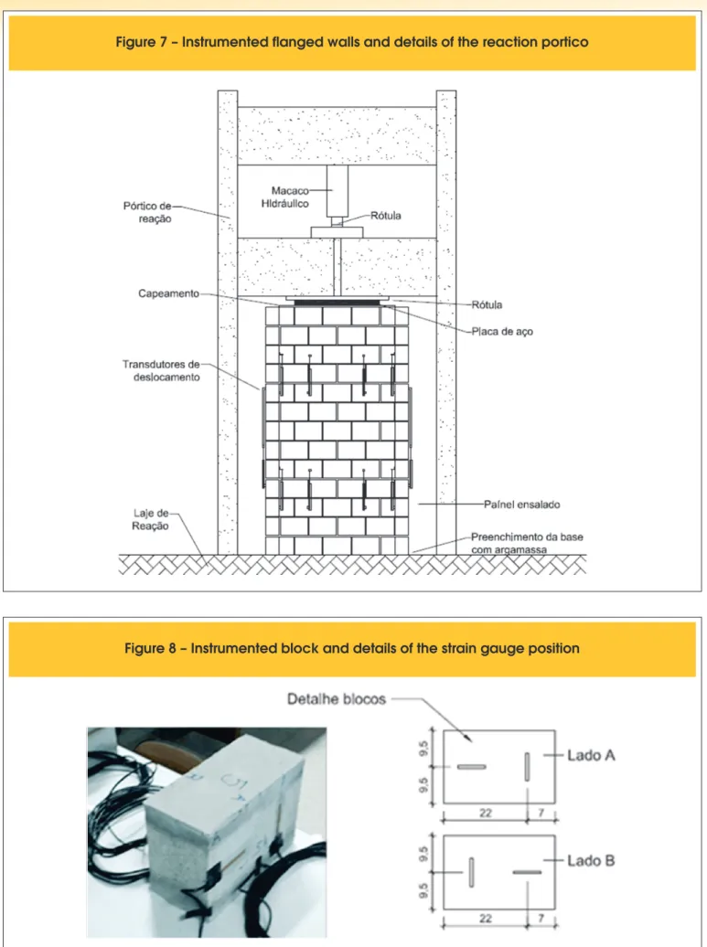
with mortar, with one cm thickness and direct bonding was used. A 90 cm long steel plate was chosen for the uniform application of the load over the web, simulating the effect of a supporting row at the top of the wall. The steel plate applied the load over the three middle blocks of the central wall,
ex-cluding the blocks that were directly attached to the flanges,
Figure [7].
The use of a slab to apply the load on the wall would have been ideal for the experiment. However, it would be more com-plex, as the test were carried out in full scale.
3.1 Geometry, construction of langed walls
and transportation
Interlocked units were applied in the construction of the langed
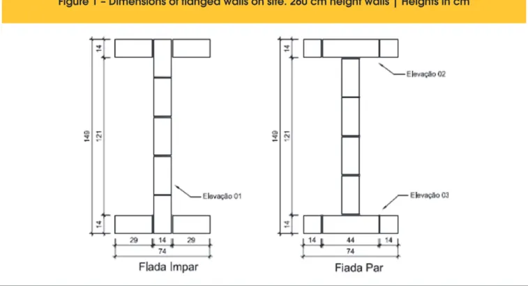
walls. Special units of 44 cm length with three hollows were used for the clamping. The specimens were constructed under metallic framing and after the cure interval they were transport-ed to the portico where they were testtransport-ed. The dimensions (in centimeters) of these walls on site are shown in Figure [1].
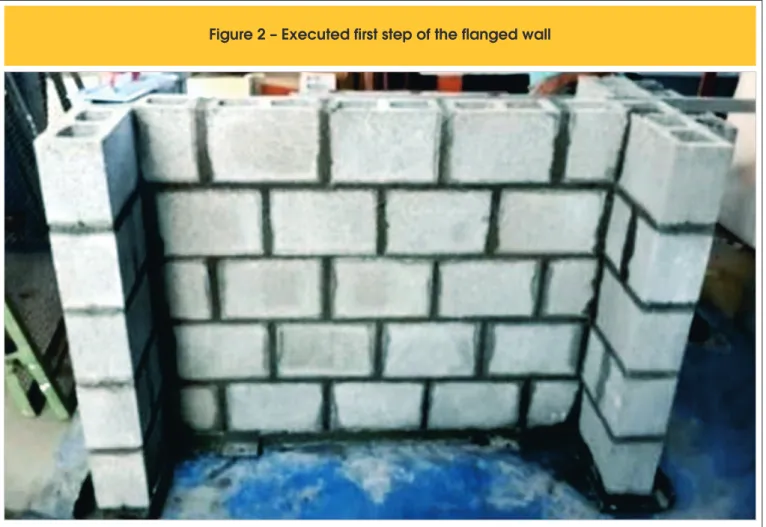
The construction of the langed walls were carried out in
three steps according to recommendations of the ABNT NBR
8949:1985 [8] norm. On the irst day, ive rows were built and
on the subsequent days, four rows were built each day. The
irst step of the masonry walls construction can be observed
in Figure [2]. For each step, three prismatic mortar specimens were molded.
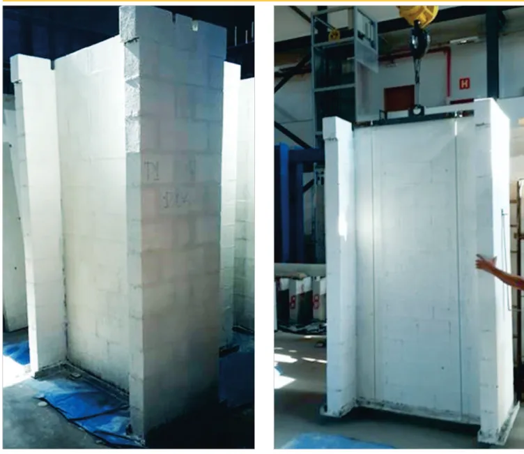
A rolling bridge transported the specimens to the testing
loca-tion. In Figure [3], a langed wall specimen being transported to
the reaction portico is shown.
3.2 Instrumentation and testing procedure
The procedures for the langed wall testing complied with the rules
from the norm ABNT NBR 8949:1985 [8] that were valid at the date of the testing. The deformations were determined below the top row, to avoid local disturbance in the load application area.
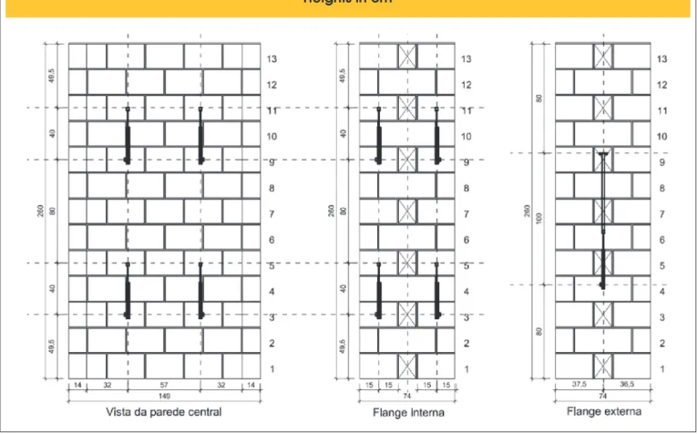
The instrumentation of the langed walls consisted of a load cell
and eighteen displacement transducers, both on the central wall
and on the langes. Figure [4] shows the elevations of the langed
walls (in centimeters) and the position of the sensors on the central
wall, the internal and external langes, respectively. The standard
length used for the calculation of vertical deformation was 40 centi-meters, which is equivalent to the length of two rows. The labelling of the displacement transducers is shown in Figure [5]. The data
acquisition system Spider was used with a reading frequency of
2 Hz.
The loading was divided in four stages and the adopted load incre-ment was 150 kN, which is equivalent to around 10% of the
expect-ed failure load. On the irst stage, three load increments were ap
-plied and subsequently it was unloaded until zero. On the second
stage, three load increments were applied and subsequently it was unloaded until 150 kN. On the third stage, subsequent increments were applied until the appearance of small fractures. On the fourth and last stage the equipment were removed and the load
incre-ment became 50 kN, until the rupture of the langed wall. After each increment, the load stayed on the langed walls
for a time greater than 5 minutes. The loads and the shorten-ing were registered at the end of this time. Figure [6] shows the
648 IBRACON Structures and Materials Journal • 2016 • vol. 9 • nº 5
Internal and external flanges
Heights in cm
!"# $!#%&'(! %)(''"(!%%#( '"*&#+(,# *!-* # ,*
instrumented langed walls at the moment it was being tested as
well as the details of the reaction structures used for the testing.
Two kneecaps were used in order to minimize the eccentricity of the load, the irst one located at the hydraulic jack and the second
one above the steel plate that was supported on the central wall. To improve the support between the metallic framing and the reaction slab and avoid the load to concentrate in local spots, a high initial strength mortar was applied under the framing of every test,
ac-cording to the arrangement pictured in Figure [7].
4
Material proprieties
A series of characterization tests were carried out in the masonry
components, concrete blocks, mortar and two block prisms, in
par-allel with the langed wall testing.
4.1 Concrete blocks
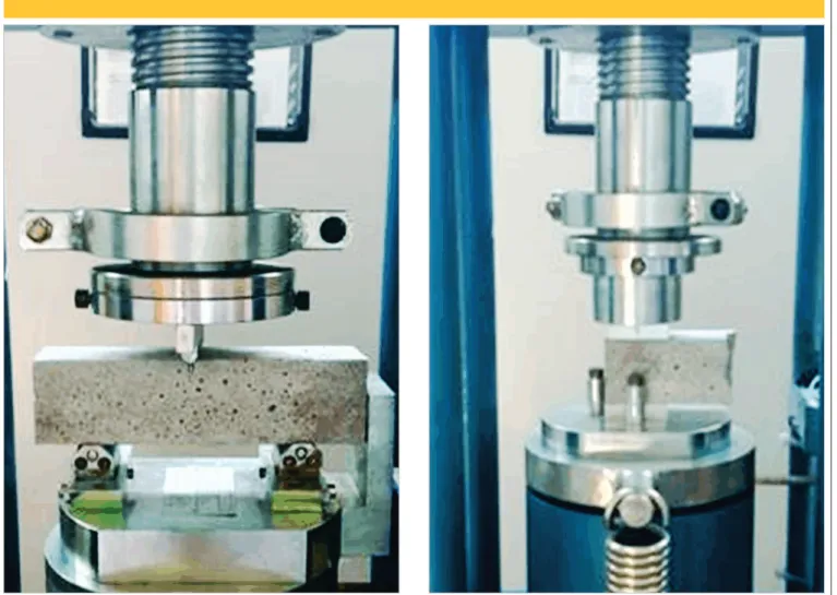
The blocks characterization was in terms of the average strength and speciic strength, in accordance with the procedures from the
ABNT NBR 12118:2014 [13] norm in six specimen. The elastic-ity modulus and the Poisson ratio were obtained from four
elec-tric strain gauge connected to the data acquisition system called AqDados from Lynx. Hence, the blocks were submitted to a load equivalent to 30% of the failure load and unloaded to achieve sta-tionary state. Then, the loading was applied at a 0,005 mm/s rate
until reaching 50% of the possible failure load and inally it was
loaded until its rupture.
From the linear interval (stress x strain) the elasticity modulus and the Poisson ratio were obtained, admitting as the linear interval values from 0.5 MPa to 30% of the average failure load of the blocks. The choice of the testing procedure was based on
previ-ous studies found in literature due to the lack of speciic norms.
Figure [8] illustrates the block instrumentation and the position of the strain gauge on the block.
4.2 Mortar
The mortar used to build the prisms and walls in this study con-tained the following materials as binders: type CP II-E-32 Portland cement, type CH I special additivated hydrated lime and natural
quartzite ine aggregate, upper usable limit.
The method proposed by Santos (2014) [14] was used for the dosage
650 IBRACON Structures and Materials Journal • 2016 • vol. 9 • nº 5
Figure 7 – Instrumented flanged walls and details of the reaction portico
the speciic compressive strength of the block (16,9 MPa), in relation to the liquid area. The testing complied with the ABNT NBR 13279:2005 [15] and ABNT NBR 15961-2:2011 [7] norms and were carried on the same day of the walls testing. Figure [9] illustrates the tests for lexural
strength and compressive strength. Six mortar specimens (5 cm x10 cm) were also built in order to obtain the static and dynamic elasticity moduli. In this case, the norms ABNT NBR 8522:1984 [16] and ABNT
NBR 15630:2009 [17] were used, respectively.
4.3 Two block prisms
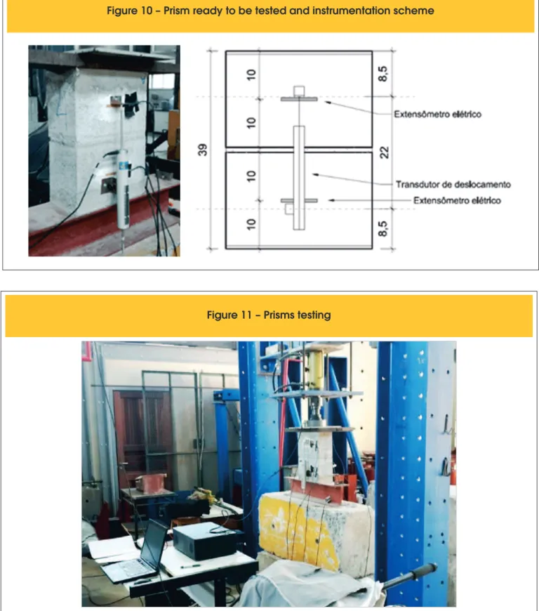
The determination of the prisms compressive strength was carried
using the procedures from the ABNT NBR 15961-2:2011 [7] norm.
The data acquisition system AqDados from Lynx, with reading
fre-quency of 2 Hz, was used to measure the elasticity modulus. The
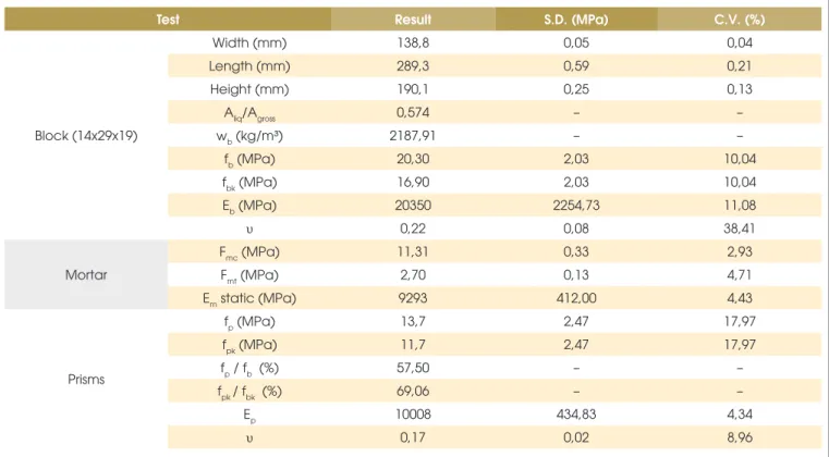
system collected data from a load cell, four electric strain gauges and two displacement transducers as illustrated in Figure [10]. The prisms were submitted to the testing with manual load appli-cation in a portico. Figure [11] illustrates the arrangement set for the experiment. The elasticity modulus of the prisms and the Pois-son ratio of the blocks were calculated in the interval of the secant curve correspondent to 5% to 30% of each specimen failure load, according to the norm criteria.
5. Results and discussion
The experimental results are presented in this topic as well as an
interpretation of the results and comparison with those found by other researchers.
5.1 Material proprieties
The average value found in the compression strength test of the
concrete block was 20.3 MPa and the speciic strength was 16.9
MPa. Both results are shown in details in Table [1]. The average value found in the elasticity modulus test of the block was 20350 MPa. This value is similar to the one calculated with the formula proposed by the ACI – Building Code 318 [11] (26429 MPa), with a
diference of 23% in the result.
The prisms and the walls were built with the same mortar. The static and dynamic elasticity modulus of the mortar were 9293
MPa and 7938 MPa, respectively. The results difer from each
other in 14% but they did not show disparity in the individual tests,
as the coeicient of variation was lower than 5%. Its average compression strength was 11.31 MPa and the lexural strength was 2.70 MPa.
The prisms testing aimed to analyze the strength characteristics of
the masonry elements, especially the loads and modes of failures,
to analyze the axial deformability of the two block prisms and to
compare the results to those obtained for walls.
The failure occurred, in general, due to vertical issure, initiated and intensiied in the vertical hollow and in the block longitudinal walls. The irst issures appeared within 70 to 80% of the maxi -mum load.
652 IBRACON Structures and Materials Journal • 2016 • vol. 9 • nº 5
Figure 10 – Prism ready to be tested and instrumentation scheme
Fi
gure 11 – Prisms testing
son ratio of the prisms was in average 0.17, 22% lower than the
value found for the blocks. This is because the elasticity modulus regards the set block/mortar, being superior to those obtained only by the deformation of the block itself.
Observing the average elasticity modulus of the blocks and mor-tar, 20350 MPa and 9293 MPa, respectively, it results in a ratio of
ing of the mortar joint; while for ratios of
E
morE
b≤
0
,
6
6
the rupture occurs by stress on the blocks. In fact, during the tests verticalissures were observed in the transversal and longitudinal blocks
of the prisms.
5.2 Masonry langed walls
For a better understanding, the results were divided in ive subtop -ics: Compressive strength, deformation, modes of failure, estima-tion of transfer rates and comparative analysis between walls with and without central support.
5.2.1 Compressive strength
The load correspondent to the appearance of the irst visible issures
in each test and that of the failure are presented in Table [2]. Table [3] shows the failure loads considering independent walls and walls with interaction. The compressive strength of the prismatic
mor-tar specimens, which were retained during the construction of the
langed walls, had similar results to what was expected (12.0 MPa),
only a little over due to a longer curing time of the mortar.
5.2.2 Deformation
Only the deformation measured in the lower part of the wall was
used to calculate the elasticity modulus of the langed walls. In the
upper region, where the load transfer from the central wall to the
langes occur, the determination of the stress acting on the web / lange is complex and uncertain. The load interval used to calcu -late the stress was between 30% and 40% of the failure load, as linear scopes are observed in this interval and the load values are
lower than the irst issure load.
Table 1 – Physical and mechanical proprieties of the materials obtained in the tests
Test Result S.D. (MPa) C.V. (%)
Block (14x29x19)
Width (mm) 138,8 0,05 0,04
Length (mm) 289,3 0,59 0,21
Height (mm) 190,1 0,25 0,13
Aliq/Agross 0,574 – –
wb (kg/m³) 2187,91 – –
fb (MPa) 20,30 2,03 10,04
fbk (MPa) 16,90 2,03 10,04
Eb (MPa) 20350 2254,73 11,08
υ 0,22 0,08 38,41
Mortar
Fmc (MPa) 11,31 0,33 2,93
Fmt (MPa) 2,70 0,13 4,71
Em static (MPa) 9293 412,00 4,43
Prisms
fp (MPa) 13,7 2,47 17,97
fpk (MPa) 11,7 2,47 17,97
fp / fb (%) 57,50 – –
fpk / fbk (%) 69,06 – –
Ep 10008 434,83 4,34
υ 0,17 0,02 8,96
Table 2 – First fissure load and maximum load
Wall type Test First fissure load (kN) Maximum load (kN)
With central support
1 642,48 879,46
2 728,25 1294,60
3 703,00 952,73
Average (kN) 697,24 1042,26
S.D. (kN) 44,08 221,58
C.V. (%) 6,38 21,26
Without central support
4 545,82 704,61
5 478,16 593,77
6 621,10 673,24
Average 581,69 657,20
S.D. (kN) 90,51 57,13
654 IBRACON Structures and Materials Journal • 2016 • vol. 9 • nº 5
In order to determine the loads and stresses of the langed walls
with central support, the ratio between the deformations of the
dis-placement transducers placed on the web and on the langes was
calculated. All of them were placed on the same height; therefore
the rate of load transfer from the web to the langes was estimated. For the langed walls without central support, on the other hand,
the elasticity modulus was calculated using the deformation in the
lower part of the langes. The stress was obtained considering half the load of each lange, being the load transfer from the web to the langes of 100% giving the condition of no support of the central wall. It was possible to observe that in the lower region of the langed
wall, the readings of the displacement transducer on the web and
the langes were closer, indicating the occurrence of interaction. The deformation of the langes in the lower region were superior to those
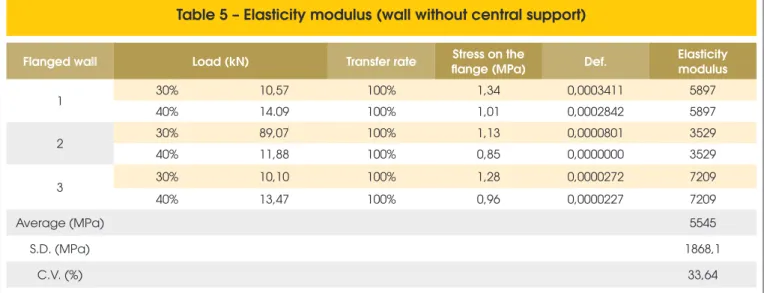
measured in the upper region. Meanwhile, on the web there was a reduction on the deformation in the lower region when compared to the upper one. The results are shown in Table [4] and Table [5].
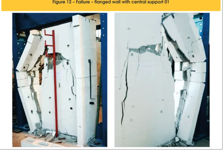
5.2.3 Modes of failure
The modes of failure can be observed on Figure [12] to Figure
[17]. On the langed walls with central support, the modes of failure Type Stress in independent wall (MPa) Stress in walls with interaction(MPa)
Average (MPa) S.D. (MPa) C.V. (%) Average (MPa) D.P. (MPa) C.V. (%)
With central
support 6,15 1,31 21,26 2,75 0,58 21,26
Without central
support 3,17 0,27 8,72 – – –
Table 4 – Elasticity modulus (wall with central support)
Flanged wall Load (kN) Stress on the
web (MPa) Def. 1 Def. 2
Elasticity modulus 1
Elasticity modulus 2
1 30% 26,38 1,20 0,0004351 0,0011511 7740 3306
40% 35,17 2,04 0,0003273 0,0008988 7740 3306
2 30% 38,84 1,25 0,0006610 0,0013659 7756 3016
40% 51,78 2,95 0,0004406 0,0007993 7756 3016
3 30% 28,58 0,81 0,0004683 0,0009824 3870 5729
40% 38,11 1,58 0,0002691 0,0008478 3870 5729
Average
(MPa) 5236
S.D. (MPa) 384,6
C.V. (%) 7,35
1 – Right side of the web; 2 – Left side of the web.
Table 5 – Elasticity modulus (wall without central support)
Flanged wall Load (kN) Transfer rate Stress on the
flange (MPa) Def.
Elasticity modulus
1 30% 10,57 100% 1,34 0,0003411 5897
40% 14.09 100% 1,01 0,0002842 5897
2 30% 89,07 100% 1,13 0,0000801 3529
40% 11,88 100% 0,85 0,0000000 3529
3 30% 10,10 100% 1,28 0,0000272 7209
40% 13,47 100% 0,96 0,0000227 7209
Average (MPa) 5545
S.D. (MPa) 1868,1
Figure 12 – Failure – flanged wall with central support 01
656 IBRACON Structures and Materials Journal • 2016 • vol. 9 • nº 5
Figure 16 – Failure – flanged wall without central support 05
658 IBRACON Structures and Materials Journal • 2016 • vol. 9 • nº 5
of the irst two walls were similar, typical of a failure by combined compression and shear, with horizontal traction failure along the web and shear in the lower region at the web/lange interface. The issures started vertically below the load application point (pass
-ing through the horizontal joints of the blocks) and staggered (only through the vertical and horizontal mortar joints).
In the third langed wall with central support, the failure occurred
by compression in the upper region of the central wall in the
blocks below the irst row. By increasing the load, the issures
propagated down.
On the langed walls without central support, the three tests
showed similar behaviors, in which the failure occurred abruptly
with the sudden opening of big issures, typical of shear failure. In
all the cases, the failure occurred in only one side with a vertical
issure along the web. The efect of bending on the langes can be veriied by the horizontal cracks occurring at the joints of the
intermediate rows.
Generally, from the load application point, the cracking displaced
vertically, with a slight inclination, and on the lower rows, they
in-clined in the direction of the langes, clearly indicating the shear on the web/langes interface.
5.2.4 Transfer rate
Load transfer rate to the langes is understood as the relationship
between the portion of the load applied on the web that is absorbed
by the langes and the maximum load that can be transferred to the langes in the case of a complete interaction. For the totally sup
-ported “H” shaped walls, it was observed that the transfer rate is
conditioned by the level of load applied on the central wall as much as on the position evaluated on the wall (height).
For the panels with central support, the interaction rate was deter-mined based on the strain relationships and the strength of
materi-als and mechanical equations. Neglecting the lexion efect, it can
be said that:
(5.1)
(
)
tflange
F
r
k
F
´
+
=
\
2
1
where:÷
÷
ø
ö
ç
ç
è
æ
´
´
=
flange flange web webE
A
E
A
k
,
E
web=
E
flange=
E
masonry;
web flange
r
e
e
=
and
F
t is the total load applied at the top.On the other hand, for the total uniformization case:
(5.2)
(
web flange)
t t
wall
=
A
+
2
F
´
A
s
for walls with central support
(5.3)
for walls without central supportflange t
wall uni
flange
A
F
=
s
-1´
In which:
t wall
σ
is the uniform stress on the web and the langesuni flange
F
is the net force on the lange correspondent to the uni-form tension.
The ratio between the average deformations on the langes and the webs, obtained experimentally for the langed walls with and
without central support, respectively, are shown on Table [6], as
well as the interaction rates for the lange on the panels with cen -tral support.
Figure [18] and Figure [19] show the relationship between the
av-erage deformation on the lange and the avav-erage deformation on
the wall as a function of the level of load applied on the tests for both series.
5.2.5 Comparative analysis between langed walls with and
without central support
It cam be said that for the “H” shaped walls without central support (Average failure load 657 kN) there was a decrease of 36.9% in the average failure load when compared to the langed wall series with
central support (Average failure load 1042 kN). This is due to the reduction in 45% of the supporting area.
Based on the theoretical procedures for distribution of vertical ac-tions so-called independent walls and walls with interaction, it was
concluded that the stresses required by the web and the langes are around 6.15 MPa and 2.75 MPa, respectively, for langed walls
with central support. The stress considering an independent wall
was 3.17 MPa, for walls without central support.
From the results obtained for the compressive strength of the blocks
and for the prism/block eiciency it was possible to estimate the fail
-and the load transfer rate for the flanges
Test
Average deformation on flange / Average deformation
on web (r)
Load transferred to flange (kN)
Max. strength on flange
Transfer rate to flange (%)
Upper
region Lower region
Upper
region Lower region (kN)
Upper
region Lower region
Panel 1 0,26 0,57 107,2 182,1 240,4 44,60 75,76
Panel 2 0,19 0,64 123,4 286,4 353,3 34,93 81,06
Panel 3 0,18 0,56 86,9 195,2 260,0 33,42 75,07
ure load of the langed walls with central support as being 1302.60 kN, using the independent walls method. However, when the stif
-ness efect and the slender-ness ratio (R) are considered or not, the estimated value of the failure load are 1276.55 kN and 1172.34 kN,
respectively. The diference between the expected values and the
average obtained experimentally relates to the fact that
masonry-langed walls can fail due to the stress concentration in local spots. The average elasticity modulus of the langed walls was 5236 MPa
Figure 18 – Average deformation ratio (flange/web) – flanged walls with central support
660 IBRACON Structures and Materials Journal • 2016 • vol. 9 • nº 5
(web – wall with central support) and 5545 MPa (lange – wall without central support) and, despite being calculated diferently,
the values were similar.
The masonry elasticity modulus according to the ABNT NBR 15961-1:2011 [3] norm can be estimated as being 800 x fpk. For fpk equals to 11.7 MPa, the expected elasticity modulus would be 9360 MPa, which is greater than the one found in this study. Other authors suggest equations to calculate the elasticity
modu-lus. The Equation (2.4) proposed by Gomes (1993, apud CARV
-ALHO, 2007) [12] allows the calculation of the masonry elasticity
modulus as a function of the elasticity modulus of the mortar and the block. Using the Equation (2.4) for the data found in this ex-periment (
E
a being 8616 MPa andE
b being 20350 MPa), the elasticity modulus of the masonry is 8995 MPa.The Equation (2.5) proposed by Dhanasekar (1985, apud
MOHAM-AD, 2007) [9] suggests a linear relationship to establish the elasticity
modulus of the masonry as a function of its compressive strength. Using the theoretical methods for calculating stresses (independent walls and walls with interaction), two values of elasticity modulus were
found. Table [7] shows the results of elasticity modulus found in this
study as well as those obtained from equations available in literature. It is clear that the model with closer results to those found in this
study was from Dhammasekar (1985, apud MOHAMAD, 2007) [9].
The formation of strut on the central wall was evident in the failure mode
due to the formation of cracking and issures with inclination between 60° and 45° from the central walls to the langes. On the walls with central support, the load lux to the langes was more intense on the
lower rows. On the other hand, the behavior was inverted on the walls
without central support as the lux was more intense on the upper rows. Diferently from the failure mode of the irst series (with support),
on the second series (without support) the failure occurred abruptly and in a fragile way, as expected in a shear failure. In this case, the
issures started in a loading stage close to the maximum loads and extended through the length of the langed walls.
Regarding the ratio of langes/web deformation in the lower region within the levels of loading analyzed, the walls (with and without
support) had similar behavior, as seen in Table [6].
The loading transfer rate from the web to the langes in the lower region of the langed walls with central support was approximately 77.30%. For the panels without central support the transfer rate
was 100,00%.
6. Conclusion
n The langed walls with and without central support evaluated
in this study had direct bonding and did not have supporting
straps. The average failure load for totally supported langed walls was 1042 kN and for langed walls without central sup
-port was 657 kN, being the coeicient of variation for walls with
central support 21.26%. A reduction in the failure load close to
37% was observed for a reduction in supporting area of ap -proximately 45%.
n It was observed that the deformations in the lower region of the central wall were low when compared to the upper region. This fact can be explained by the occurrence of load transfer
from the central wall to the langes, reducing the acting stress
through the interlocking blocks.
n The elasticity modulus were relatively low when compared to the value proposed by the Brazilian norm. However, several
expressions proposed in literature for its calculation have very diverging numerical results. The deformations used in this study were the ones acquired from the lower region for being a better representation of the reality.
n The experimental results showed a diferent behavior for langed walls with and without central support, in particu -lar regarding the failure mode. While a combined shear and
compression failure occurred in the langed walls with central support, a purely shear failure occurred on the langed walls
without central support.
n The failure modes were similar on the three tests in which the central walls were supported and it was clear that the failure occurred mainly on the central wall, bellow the load applica-tion point, with diagonal and staggered cracking. The failure occurred along the entire wall, passing through the blocks and the mortar joints.
n Observing the failure mode and the cracks on the panels with-out central support, the applied load was transferred to the
langes through the upper rows, generally speaking, on the irst
six to eight rows out of thirteen in total. Despite taking all the precautions during the tests, there was load eccentricity as one side deformed more than the other one.
n The estimation of the load transfer rate from the web to the
langes in this study was based on the deformation ratio of
the upper region to the lower region of the panels. The
aver-age interaction rate was approximately 37.65% and 77.30%
on the upper and lower regions, respectively, evidencing that the interaction occurs along the height of the wall. The load transfer rate for the panels without central support, on the other hand, was 100%, as all the load was transferred to
the langes.
Table 7 – Masonry elasticity modulus
Type
Experimental program
ABNT NBR
15961-1:2011 Gomes (1993)
Dhannasekar (1985) – independent wall
Dhannasekar (1985) – walls with
interaction MPa
With central
support 728,25 8960 8995 5329 2732
Without central
n For the langed walls examined in this study, from deformations measured at the base of the walls to load values up to 40-50% of the failure load, it is concluded that there was a transfer rate
of vertical forces from the central wall to the langes of around 70%. This evidences that there was interaction between the
walls and indicates that the distribution of vertical loads shall be considered in service load buildings, as in the method of walls with interaction. However, it was observed that the failure of walls with central support started at the top of the wall, where
there was no vertical load transfer to the adjacent langes yet,
as observed by other authors in a number of studies, which means that in this case, the most adequate method is the in-dependent walls one. Few specimens and a single geometry
of “H” shaped walls were examined in this study. Therefore, further investigation is necessary in order to get deinite con -clusions and to recommend the use of theoretical methods to project structural masonry buildings with high strength con-crete blocks.
7. Acknowledgments
The authors would like to acknowledge Fapemig, Capes, the Civil Engineering Department at the Universidade Federa de Viçosa and the Structures Department at the Universidade Federal de
Minas Gerais for the support to execute this study, as well as the
enterprise Blojad for providing the concrete blocks.
8. References
[1] BUILDING CODE REQUIREMENTS FOR MASONRY
STRUCTURES, ACI 530-02/ ASCE 5-02/ TMS 402-02. Re-ported by the Masonry Standards Joint Committee, 2002. [2] EUROPE COMITEE FOR STANDARDIZATION. Eurocode
6, EN 1996-1-1: Design of masonry structures – Part 1-1:
General rules for reinforced and unreinforced masonry struc -tures buildings. Belgium, 2005.
[3] ASSOCIAÇÃO BRASILEIRA DE NORMAS TÉCNICAS.
NBR 15961-1: Alvenaria estrutural – Blocos de concreto, Parte 1: Projeto. Rio de Janeiro: ABNT, 2011. 42p.
[4] CAPUZZO NETO, VALENTIM. Estudo teórico e experimen -tal da interação de paredes de alvenaria estrutural submeti-das a ações verticais. 2000. 144f. Dissertação (Mestrado), Escola de Engenharia de São Carlos, São Paulo, 2000.
[5] ANDOLFATO, R. P. Estudo teórico e experimental da intera -ção de paredes em edifícios de alvenaria estrutural. 2006. 232f. Tese (Doutorado), Escola de Engenharia de São Car-los, São Paulo, 2006.
[6] OLIVEIRA, L. M. F. Estudo teórico e experimental do com -portamento das interfaces verticais de paredes
interconecta-das de alvenaria estrutural. 2014. 272f. Tese (Doutorado),
Escola de Engenharia de São Carlos, São Paulo, 2014.
[7] ASSOCIAÇÃO BRASILEIRA DE NORMAS TÉCNICAS.
NBR 15961-2: Alvenaria estrutural – Blocos de concreto, Parte 2: Execução e controle de obras. Rio de Janeiro: ABNT, 2011. 42p.
[8] ASSOCIAÇÃO BRASILEIRA DE NORMAS TÉCNICAS.
NBR 8949: Paredes de alvenaria estrutural – Ensaio à compressão simples – Métodos de ensaio. Rio de Janeiro:
ABNT, 1985. 7p.
[9] MOHAMAD, G. Mecanismos de ruptura da alvenaria de blo
-cos à compressão. 2007. 290f. Tese (Doutorado), Escola de Engenharia, Universidade do Minho, Portugal, 2007. [10] COMITÉ EURO-INTERNATIONAL DU BETÓN. CEB-FIP
mode code 1990. Bulletin d’Information, 1990.
[11] AMERICAN CONCRETE INSTITUTE. ACI 318-11 – Building Code Requirements for Structural Concrete and Commen-tary. Detroit, 2011.
[12] CARVALHO, J. D. N. A contribuição de enrijecedores later
-ais para a ação do efeito arco na alvenaria estrutural. 2007.
284f. Tese (Doutorado), Universidade Federal de Santa
Ca-tarina, Florianópolis, 2007.
[13] ASSOCIAÇÃO BRASILEIRA DE NORMAS TÉCNICAS. NBR 12118: Blocos vazados de concreto simples para Al -venaria – Métodos de ensaio. Rio de Janeiro: ABNT, 2014. 14p.
[14] SANTOS, W. J. Desenvolvimento de metodologia de dosa-gem de argamassa de revestimento e assentamento. 2014. 155f. Tese (Doutorado). Departamento de Engenharia Civil, Universidade Federal de Viçosa, Viçosa. 2014.
[15] ASSOCIAÇÃO BRASILEIRA DE NORMAS TÉCNICAS. NBR 13279: Argamassa para assentamento e revestimento
de paredes e tetos - Determinação da resistência à tração
na lexão e à compressão. Rio de Janeiro: ABNT, 2005. 9p. [16] ASSOCIAÇÃO BRASILEIRA DE NORMAS TÉCNICAS.
NBR 8522: Concreto – Determinação do módulo estático
de elasticidade à compressão. Rio de Janeiro: ABNT, 2008, 16P.
[17] ASSOCIAÇÃO BRASILEIRA DE NORMAS TÉCNICAS.
NBR 15630: Argamassa para assentamento e revestimento
de paredes e tetos – Determinação do módulo de elastici -dade através da propagação de onda ultra-sônica. Rio de Janeiro: ABNT, 2009. 4p.
[18] CHEMMA, T.S.S. e KLINGNER, R.E. Compressive strength