*e-mail: [email protected]
Influence of the Oxidation Step on the Behaviour and the
Performances of an Oxygen Carrier in Fixed Bed Reactor
Lucia Blasa, Sophie Dorgea*, Nabila Zouaouia, Arnold Lambertb, Patrick Dutourniéc
aLaboratoire de Gestion des Risques et Environnement – GRE, Université de Haute Alsace – UHA,
3bis, rue Alfred Werner, 68093 Mulhouse, France bIFP Energies Nouvelles, BP 3, 69360 Solaize, France
cInstitut de Science des Matériaux de Mulhouse – IS2M, CNRS LRC 7228, 15 rue Jean Starcky, BP 2488, 68057 Mulhouse, France
Received: March 7, 2013; Revised: August 31, 2013
Chemical Looping Combustion is a promising technology for clean power generation with integrated CO2 capture. In this process the oxygen required for combustion is provided by a metal oxide. This work deals with the development of an experimental procedure to study performances
of an oxygen carrier during oxidation/reduction cycles and the inluence of the oxidation step on its behaviour. Tests were performed in a laboratory ixed bed reactor, with NiO/NiAl2O4, a promising oxygen carrier, and CO as fuel. Two different protocols of oxidation were studied. Results reveal
that the oxidation step conditions can change the performances of the oxygen carrier. A signiicant
decrease in total reduction capacity was observed using the regeneration step at high temperature due to structural changes in particles. SEM analysis reveals that particle surface contains different crystallites according to this procedure. With the second procedure (oxidation in temperature ramp), nickel is partially agglomerated.
Keywords: CLC, oxygen carrier, CO oxidation, SEM, nickel agglomeration
1. Introduction
It is well known that the combustion of fossil fuels for power generation emits large amounts of carbon dioxide, which is one of the most important greenhouse gases contributing to global warming. The CO2 concentration in the atmosphere has increased considerably in recent decades (from 318 ppm in 1958 to 400 ppm in may 20131), and although the effects of increased levels of greenhouse
gases are dificult to quantify, it is generally accepted
that a reduction in emissions of these gases is necessary2. Fossil fuels will continue to be used as principal sources of energy during the next decades. Therefore it is important to minimize CO2 emissions. It can be achieved by energy savings and development of renewable energy sources,
but also by developing new eficient processes for CO2
capture and sequestration (CCS). Current CO2 capture technologies consist in the CO2 separation from industrial
lue gas streams. This last one can be stored or mineralised3. These processes have the major disadvantage of high costs
and energy penalties, because of the signiicant quantities
of gas which must be treated. These processes lead to a
relative reduction of 15-20% of the overall eficiency of a
power plant4.
Chemical Looping Combustion (CLC) is an innovative technology that can be used for clean power generation or as an alternative process for oxidizing organic wastes, because the CO2 capture process can be easily integrated with lower energy penalties5. The main advantage of this technology compared to conventional combustion is that
combustion occurs without air, the oxygen required for this reaction is directly provided by a metal oxide as an oxygen carrier. During CLC process, the oxygen carrier is continuously circulated between two interconnected
luidized bed reactors where it is alternatively oxidized and
reduced6,7. In the fuel reactor, the oxygen carrier is reduced by the combustible according to reaction (1), and in the air reactor it is regenerated according to reaction (2).
The lue gases released from the air reactor contain mainly N2 and unreacted O2. They can be emitted to the atmosphere without any treatment. Exhaust fumes from the fuel reactor contain mostly CO2 and H2O. After water condensation, almost pure CO2 can be obtained, therefore CO2 capture occurs at low energy consumption. This process
also ensures that no thermal NOx will be produced by Zeldovitch mechanism in the lue gas, due to the absence
of extremely high temperatures as it is seen in classical
combustion for both premixed and diffusion lames8,9.
(2n+m)MyOx+CnH2m→ (2n+m)MyOx-1+mH2O+nCO2 x ≥ 1 (1)
(2n+m)MyOx-1+(n+0.5m)O2→ (2n+m)MyOx (2)
Reaction (2) is strongly exothermic, while reaction (1) can be either endothermic or exothermic depending on the fuel and the oxygen carrier used. The total amount of heat released from both reactions is the same as the heat released during conventional combustion, and no additional energy is needed in the CO2 separation process, except the energy
The selection of suitable oxygen carrier is a key issue for the large-scale application of CLC, and the performance of oxygen carrier particles will determine the feasibility of the process. Many efforts have been made to develop
eficient oxygen carriers for the CLC process. More than
700 different products have been developed and tested10, and
several oxides of transition metals such as Ni, Cu11, Mn12 and Fe13 have been proposed as the most suitable materials for oxygen carriers in CLC14,15. The metallic oxides are generally supported on a porous material (Al2O3, SiO2, TiO2, ZrO2 and Yttria-Stabilized Zirconia), which is inert and stable at high temperature and increases the particles’ mechanical strength and attrition resistance. The binder also provides a higher surface area needed for the reaction16.
Ni-based oxygen carriers which show high reactivity
and good performances, in large range of temperature, are
the most analysed materials in the literature. Nevertheless,
thermodynamic restrictions prevent complete conversion of methane into CO2 and H2O with this oxygen carrier, and this generates small amounts of CO and H2 in the exhaust gas of the fuel reactor17,18. For Ni-based oxygen carriers, NiAl
2O4 is considered one of the best binders19.
Intensive works have been performed in the past about the reactivity and kinetic determination of the reduction and oxidation steps of oxygen carriers. These results are strategic for the development of industrial reactors. Different studies dealing with the performances of oxygen carriers can be found in the literature; they have been carried out at laboratory scale: usually Thermogravimetric Analyses TGA20 or at pilot scale21,22. With TGA studies, the degree of conversion of the materials can be obtained, but this analysis is not carried out in the same operating conditions as it is observed in CLC reactors. Indeed, residence and diffusion times (fuel vs. oxygen carrier) are very different in the two
operating conigurations.
Another way to study an oxygen carriers’ performance
at laboratory scale is the ixed bed reactor. In this case, the gas low goes through the bed and the mass transfer
is mainly governed by forced convection. Therefore, this technique allows working at laboratory scale in conditions that are closer to the ones used in a CLC process. However,
there are few studies operated in ixed bed reactors. For
example, Mattisson et al.23 investigated the feasibility of using Fe2O3 as an oxygen carrier in a ixed bed reactor (in quartz) at 950 °C. They observed that the rates of reduction
and oxidation are suficient to use it in a CLC process. Q.
Song et al.24 studied in a ixed bed reactor, the reactivity and stability of CaSO4. They showed that 950 °C is the optimal reduction temperature to minimize secondary products and agglomeration, and they concluded that CaSO4 is a potential oxygen carrier for CLC. Ryu et al.25 studied in a
ixed bed reactor the reactivity and the carbon deposition during reduction, with NiO as oxygen carrier supported on
bentonite.
There are several works devoted to the behaviour of oxygen carriers with CH4 as a fuel; however, few studies concerning the reactivity of CO or syngas have been performed26.
The present study deals with laboratory scale
experiments on NiO/NiAl2O4 oxygen carrier (one of the
most powerful material) in a ixed bed reactor with CO as
fuel. The objective of this work is to develop an experimental procedure to study the behaviour of an oxygen carrier during reduction-oxidation cycles, in terms of fuel oxidation performances and regenerability to optimize its life time.
To ind the best procedure of oxygen carrier regeneration, we have studied the inluence of the oxidation step on the
reduction capacity. Two different oxidation protocols were studied and compared.
2. Experimental
2.1.
Materials
The oxygen carrier used in this study is NiO supported on NiAl2O4. It was supplied by IFP Energies Nouvelles,its
composition is of 60 wt. % NiO and 40 wt. % NiAl2O4 and the particle size is in the range of 100-300 µm. The particles were prepared by granulation (in a Guedu granulator) and then, they were calcined at 1200 °C for 2 hours.
2.2.
Experimental device
Laboratory scale experiments were performed in a vertical quartz reactor of 6 mm of internal diameter, with a fused silica frit (Figure 1). This small reactor allows us working with a minimal mass of oxygen carrier and a
signiicant bed height. The reactor is in a vertical tubular
Pekly/ Herrmann-Moritz furnace (the sample is placed in the isothermal area of the oven). Two K-type thermocouples are placed below the silica frit and just above the sample, to control the temperature in the reactor and in the material.
The fuel used in this study is a mixture of CO and nitrogen (concentration 0.2 vol.%), it was chosen because
it simpliies the analysis of the results and also it avoids
the implementation of considerable resources. It is also an intermediate of reaction when hydrocarbons are used as fuel.
The injected gas low rate (oxidising and reducing mixtures) is controlled by four BROOKS 5850 mass low controllers and ixed at 50 NL.h–1 for all the tests. Mole fractions of CO and CO2 of exhaust gases are measured
online by an infrared analyser (Rosemont NG2000, range
0-1%). In addition, the oxygen concentration is measured by a paramagnetic analyser (Rosemount X-stream with two ranges 0-20% and 0-100%). The data acquisition (time, temperature and concentrations) is carried out using a
module NUDAM and all the data are recorded in real time
throughout the tests.
2.3.
Procedure
Two different procedures to oxidize and reduce the sample have been studied and compared.
Procedure 1 consists of an oxidation of the oxygen carrier under air, from ambient temperature to operating temperature (750 °C, at 10 °C.min–1). When the operating temperature is reached, the inerting step under nitrogen
starts and it is inished when the oxygen analyser shows
that the concentration of oxygen in the device is zero (about 30 minutes). At this time, a mixture of CO (concentration 0.2 vol. %) and nitrogen is introduced in the reactor to reduce
CO in the exhaust gas is equal to the concentration of CO injected (complete reduction). After the reduction step the inert gas is injected again to avoid mixing of oxidant and reducing gases. Then a new oxidation-reduction cycle is started and performed at operating temperature (750 °C).
Procedure 2 is similar to the irst one, the irst cycle
is carried out exactly in the same conditions, but for the following ones, the sample is cooled down to ambient temperature under nitrogen before starting a new oxidation cycle.
Therefore the main difference between both procedures
is that the oxidation in the irst one is carried out at the
operating temperature (750 °C) while in the second one the sample is always cooled after the reduction, and during the oxidation step it is heated from room to operating temperature.
2.4.
Sample characterization
Specific surface area measurements are performed by nitrogen adsorption (BET methodology) at 77K (MICROMERITICS ASAP 2010) after sample degassing at 250 °C overnight.
Oxygen carrier surface observations are carried out at
various magniications using a Philips XL30 FEG Scanning
electron microscope (SEM) equipped with an energy dispersive X-ray spectrometers (EDX).
3. Results
3.1.
Experimental results using procedure 1.
The initial test is performed according to the first procedure (oxidation step at operating temperature), with
0.28 g of NiO/NiAl2O4 and the concentration of CO injected
during the reduction step is ixed at 2000 ppm (total gas
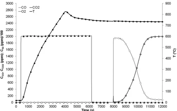
low of 50 NL.h–1). Figure 2 shows the temperature and the
outlet gas concentration as a function of time for the irst
three oxidation-reduction cycles. It can be observed that
at the beginning of the irst reduction cycle there is a high
conversion (almost complete) of CO to CO2. However, at the beginning of the second and the third reduction cycles, the conversion of CO is not complete. The curves are integrated to obtain the amount of CO2 produced and CO oxidised during each cycle. The maximum experimental error observed for the CO/CO2 analyser is about 3 ppm. We have integrated the curves with this error in each point (±3 ppm) and from these two additional integrations, we obtained a systematic error for the total capacity around 0.01 mmol. Results are shown in Table 1.
A decrease of the reduction capacity of the oxygen carrier (around 10%) is observed from cycle 2. This decrease is probably due to a local important exothermicity (100-120 °C) during the oxidation step as observed on Figure 2. This high temperature during regeneration step
probably modiies the Ni-based particles.
3.2.
Cycles performed using procedure 2
To avoid the local rising in temperature during the oxidation step observed with the first procedure, the following tests are performed according to the second one (the sample is preliminary cooled to room temperature before the regeneration step). The obtained results for the
irst oxidation- reduction (after an activation cycle) test are
shown in Figure 3.
In these conditions no exothermicity is observed during the regeneration of the oxygen carrier.
3.3.
Reproducibility of cycles
Using the first procedure it is observed that the
successive cycles are not reproducible, and there is a
Table 1. Amount of CO2 produced and CO oxidised during reduction cycles (procedure 1 and 2).
Procedure 1 Procedure 2
Moles of CO2 produced Moles of CO oxidised Moles of CO2 produced Moles of CO oxidised
Cycle 1 2.15 10–3 ± 0.01 10–3 2.21 10–3 ± 0.01 10–3 2.32 10–3 ± 0.01 10–3 2.35 10–3 ± 0.01 10–3 Cycle 2 1.96 10–3 ± 0.01 10–3 2.04 10–3 ± 0.01 10–3 2.33 10–3 ± 0.01 10–3 2.36 10–3 ± 0.01 10–3 Cycle 3 1.94 10–3 ± 0.01 10–3 2.01 10–3 ± 0.01 10–3 2.31 10–3 ± 0.01 10–3 2.35 10–3 ± 0.01 10–3
Cycle 4 2.30 10–3 ± 0.01 10–3 2.33 10–3 ± 0.01 10–3
Total capacity= 2.33 10–3 ± 0.02 10–3 CO/CO 2 moles
Figure 2. Oxidation-reduction cycles of 0.28 g of NiO/NiAl2O4 (0.2% CO, 750 °C, 50 NL.h
–1) according to irst procedure.
Figure 3. First oxidation-reduction cycle (after activation cycle) of 0.28 g of NiO/NiAl2O4 (0.2% CO, 750 °C, 50 NL.h
decrease in potential reduction capacity. Using the second
procedure the evolution of the oxygen carrier activity has been studied during successive oxidation-reduction cycles. The aim is to verify that no loss of reduction capacity is
observed on the NiO/NiAl2O4, with these experimental conditions over several successive cycles.
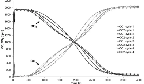
The evolution of CO and CO2 concentrations in the gas at the reactor outlet, during the reduction step, for 4 successive oxidation – reduction cycles is shown in Figure 4. All the reduction steps have been carried out at 750 °C, with a total
low rate of 50 NL.h–1, with a composition of 0.2 vol.% of CO in nitrogen.
Figure 4 shows the concentration proiles of CO and
CO2 versus time for cycles 1 to 4. Results show a relatively good reproducibility of the reduction cycles. The total
oxygen transfer capacity of the NiO/NiAl2O4 particles is practically constant for the different successive cycles (Table 1). The systematic errors for each integration is calculated as described before. Starting from these eight values we have calculated the average total capacity of the oxygen carrier (in terms of moles of oxygen reacting with the fuel) and its standard deviation.
In addition, the intersection point of CO and CO2 concentration curves for all the cycles, is approximately the same. Therefore, the behaviour of the oxygen carrier is similar for all the tests.
It can be also observed in these results a small peak of CO at the beginning of the reaction. This peak was already observed by Mattisson et al. during methane oxidation18,27. They found that this small peak appeared when the particles
are fully oxidized, but disappeared when the O/Ni ratio
decreases. They suggested that the reduction proceeds via CO and H2, which may be catalyzed by metallic Ni.
3.4.
Carbon and oxygen balance
Table 1 shows the amount of CO2 produced and CO oxidised obtained by integration of the experimental curves.
It can be assumed that the oxidation of the CO injected follows the next equation:
CO+NiO → CO2+Ni (3)
According to Equation 3, it has been considered that the oxygen available for the oxidation reaction only comes from
the NiO supported on NiAl2O4 (which amounts to 2.28.10–3 moles of oxygen).
Results of moles of CO2 produced and CO oxidised (for tests carried out according to procedure 2) are close to the theoretical number of oxygen moles available on the nickel oxide (calculated from the mass of oxygen carrier used for the tests).
In the nickel aluminate binder, there is some oxygen potentially available for the reduction of the fuel.
Mattisson et al. have studied in detail the reaction of NiO/ NiAl2O4 with alternating methane and oxygen. They have
found experimentally that NiAl2O4 can release oxygen to the fuel, but this reaction is extremely slow compared to the reaction of CH4 with NiO20,27. In our case, results obtained do not allow us to conclude that the aluminate is also partially reduced by CO.
3.5.
Characterisation of oxygen carriers
According to the procedure used, the behaviour of the oxygen carrier seems to be different. Indeed, the total reduction capacity (moles of CO2 produced) of the NiO/
NiAl2O4 changes signiicantly depending on the conditions (procedure 1 versus procedure 2) used during the oxidation step.
To explain the observed differences, a characterization of the metallic oxide samples before and after oxidation/ reduction cycles was carried out. The first observed
difference in the three samples is the colour, fresh NiO/ NiAl2O4 and the sample used with the irst procedure are green, by contrast the one used with the second procedure is dark grey/black. This difference in colours could be
explained by the fact that the NiO is green when the Ni/O
ratio is stoichiometric, and black when it is not28.
The metallic oxide samples were collected after the tests. On one side, particle agglomeration is observed in the sample oxidised by procedure 1 and a portion of the sample is stuck to the silica frit. On the other side, no agglomeration is observed on the sample oxidised by procedure 2. In this case, the grain size distribution has not apparently changed.
Speciic surface measurements on the two samples indicate
no difference between them in term of BET surface area (around 6 m².g–1).
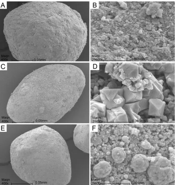
After these preliminary studies, SEM analyses were performed to study the differences between the surface of particles, depending on the oxidation procedure used. Some representative SEM micrographs are shown in Figure 5.
At a relatively low magniication, it is observed that the
shape and the surface of the particles are the same before and after the tests (Figures 5A, C and E). The particles are almost spherical and for the three samples we can also see broken particles. This is probably a consequence of the preparation method because it is also observed in fresh samples.
At high magniication, the irst thing noticed is that
each particle is composed of secondary particles. In these pictures it can be clearly seen that the secondary particles are different for each sample (Figures 5B, D and F). We can appreciate that the secondary particles of the two aged oxygen carriers are larger than those of the fresh material.
For the irst procedure it can be observed (picture 5D) that
the secondary particles are partially crystallised. However, for the second one, the secondary particles are bigger and
Figure 5. SEM micrographs of oxidised NiO/NiAl2O4. In the left micrographs at low magniication (400x), in the right the same particles
at high magniication (25600x). A and B (Before reactivity test), C and D (after reactivity tests with procedure 1), E and F (after reactivity
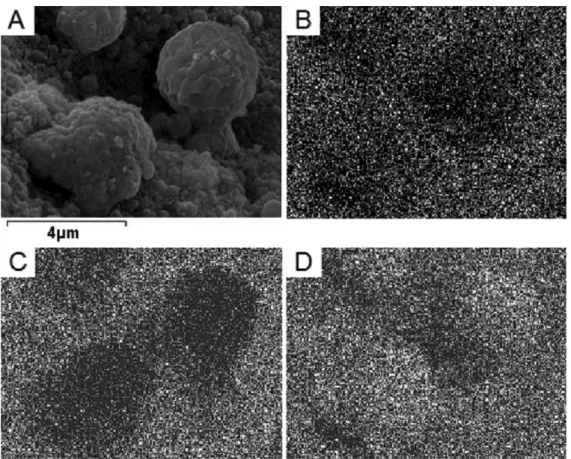
more agglomerated (picture 5F) than in the fresh sample (SEM micrograph 5B). Therefore, we can conclude that each sample has undergone different structural changes according to the operating conditions used in the cycles. Fresh and aged oxygen carrier particles were also characterized by EDX (Energy dispersive X-ray) analysis, for all samples. EDX analyses of samples from procedure 1 were not carried out owing to the instability of the particles under the electron
beam. Ni, Al and O were observed. The EDX analysis on the fresh material reveals that dispersion of Ni, Al and O is
uniform over all the surface of the particles. However, the secondary particles partially agglomerated during tests with the second procedure, are enriched in nickel and depleted in aluminium and oxygen as can be seen in Figures 6A-D.
Similar accumulations of Ni have been observed by E.
Jerndal et al.29, and they have found that these accumulations
can facilitate agglomeration, causing deluidization.
4. Conclusion
In this work, the inluence of the oxidation step on the performances of an oxygen carrier often used in CLC (NiO/ NiAl2O4) has been studied. With this objective, several oxidation and reduction cycles have been carried out in a
ixed bed reactor.
Two different procedures were studied. On one hand, with the first one (oxidation at high temperature) an
important exothermicity and a decrease in total reduction capacity is observed. On the other hand, using the second procedure (oxidation with air under a temperature ramp from ambient to the operation temperature) no exothermicity is observed and the cycles are apparently reproducible. The total capacity of the oxygen carrier remains constant after several cycles (no loss of activity) and the intersection point of CO and CO2 concentration curves is almost the same for all cycles. Furthermore, carbon balance sheets correspond very well to the oxygen balance sheet available on the metallic oxide.
Some characterization studies of the NiO/NiAl2O4 were performed to explain the different behaviours
depending on the procedure used. In a irst observation, at low magniication, particles have apparently the same size and shape for the three samples. At higher magniication,
significant differences between samples are observed. The secondary particles in the sample obtained from procedure 1 are partially crystallised. Instead, the ones from procedure 2, are partially agglomerated and enriched in nickel. Therefore we can observe that the particles have undergone different structural changes according to the oxidation conditions used in the cycles. Consequently, the chosen experimental protocol used to regenerate the oxygen
carrier can signiicantly decrease the reduction capacity and
so, can modify the process performances.
References
1. CO2Now.org. Available from: <http://co2now.org/>. 2. International Energy Agency - IEA. CO2 emissions from fuel
combustion. IEA; 2012. Available from: <http://www.iea.org/ co2highlights/co2highlights.pdf>.
3. Hossain MM and De Lasa HI. Chemical-looping combustion (CLC) for inherent separations—a review. Chemical Engineering Science. 2008; 63(18):4433-4451. http://dx.doi. org/10.1016/j.ces.2008.05.028
4. Herzog HJ. The economics of CO2 capture. London: Pergamon Press; 1999. p. 101-106.
5. Ishida M, Zheng D and Akehata T. Evaluation of a chemical-looping-combustion power-generation system by graphic exergy analysis. Energy. 1987; 12(2):147-154. http://dx.doi. org/10.1016/0360-5442(87)90119-8
6. Richter HJ and Knoche KF. Reversibility of combustion process. ACS Symposium Series. 1983; 235(3):71-85.
7. Lyngfelt A, Leckner B and Mattisson T. A luidized-bed
combustion process with inherent CO2 separation; application of chemical-looping combustion. Chemical Engineering Science. 2001; 56(10):3101-3113. http://dx.doi.org/10.1016/ S0009-2509(01)00007-0
8. Ishida M and Jin H. A Novel Chemical-Looping Combustor
without NOx Formation. Industrial & Engineering Chemistry
Research. 1996; 35(7):2469-2472. http://dx.doi.org/10.1021/ ie950680s
9. Son SR and Kim SD. Chemical-Looping Combustion with
NiO and Fe2O3 in a Thermobalance and Circulating Fluidized
Bed Reactor with Double Loops. Industrial & Engineering Chemistry Research. 2006; 45(8):2689-2696. http://dx.doi. org/10.1021/ie050919x
10. Adanez J, Abad A, Garcia-Labiano F, Gayan P and De Diego LF. Progress in Chemical-Looping Combustion and Reforming technologies. Progress in Energy and Combustion Science. 2012; 38(2):215-282. http://dx.doi.org/10.1016/j. pecs.2011.09.001
11. De Diego LF, García-Labiano F, Adánez J, Gayán P, Abad A, Corbella BM et al. Development of Cu-based oxygen carriers for chemical-looping combustion. Fuel. 2004; 83(13):1749-1757. http://dx.doi.org/10.1016/j.fuel.2004.03.003
12. Leion H, Lyngfelt A, Johansson M, Jerndal E and Mattisson T. The use of ilmenite as an oxygen carrier in chemical-looping combustion. Chemical Engineering Research and Design. 2008; 86(9):1017-1026. http://dx.doi.org/10.1016/j. cherd.2008.03.019
13. Johansson M, Mattisson T and Lyngfelt A. Investigation of Mn3O4 With Stabilized ZrO2 for Chemical-Looping Combustion. Chemical Engineering Research and Design. 2006; 84(9):807-818. http://dx.doi.org/10.1205/cherd.05206
14. Adánez J, De Diego LF, García-Labiano F, Gayán P, Abad A and Palacios JM. Selection of Oxygen Carriers for Chemical-Looping Combustion. Energy & Fuels. 2004; 18(2):371-377. http://dx.doi.org/10.1021/ef0301452
15. Cho P, Mattisson T and Lyngfelt A. Comparison of iron-, nickel-, copper- and manganese-based oxygen carriers for chemical-looping combustion. Fuel. 2004; 83(9):1215-1225. http://dx.doi.org/10.1016/j.fuel.2003.11.013
16. Ishida M and Jin H. A Novel Combustor Based on
Chemical-Looping Reactions and Its Reaction Kinetics. Journal of Chemical Engineering of Japan. 1994; 27(3):296-301. 17. Dueso C, Abad A, García-Labiano F, De Diego LF, Gayán
P, Adánez J et al. Reactivity of a NiO/Al2O3 oxygen carrier
prepared by impregnation for chemical-looping combustion. Fuel. 2010; 89(11):3399-3409. http://dx.doi.org/10.1016/j. fuel.2010.03.043
18. Mattisson T, Johansson M and Lyngfelt A. The use of NiO as
an oxygen carrier in chemical-looping combustion. Fuel. 2006; 85(5-6):736-747. http://dx.doi.org/10.1016/j.fuel.2005.07.021 19. Jin H, Okamoto T and Ishida M. Development of a Novel
Chemical-Looping Combustion: Synthesis of a Solid Looping
Material of NiO/NiAl2O4. Industrial & Engineering Chemistry Research. 1999; 38(1):126-132. http://dx.doi.org/10.1021/ ie9803265
20. Mattisson T, Johansson M, Jerndal E and Lyngfelt A. The
reaction of NiO/NiAl2O4 particles with alternating methane and oxygen. The Canadian Journal of Chemical Engineering. 2008; 86(4):756-767. http://dx.doi.org/10.1002/cjce.20083 21. Linderholm C, Jerndal E, Mattisson T and Lyngfelt A.
Investigation of NiO-based mixed oxides in a 300-W
chemical-looping combustor. Chemical Engineering Research and Design. 2010; 88(5-6):661-672. http://dx.doi.org/10.1016/j. cherd.2009.11.004
22. Sedor KE, Hossain MM and De Lasa HI. Reducion
Kinetics of a Fluidizable Nickel-Alumina Oxgen Carrier for
Chemical-Loping Combustion. Canadian journal of chemical engineering. 2008; 86(3):323-334. http://dx.doi.org/10.1002/ cjce.20072
23. Mattisson T, Lyngfelt A and Cho P. The use of iron oxide as an oxygen carrier in chemical-looping combustion of methane with inherent separation of CO2. Fuel. 2001; 80(13):1953-1962. http://dx.doi.org/10.1016/S0016-2361(01)00051-5
24. Song Q, Xiao R, Deng Z, Zhang H, Shen L, Xiao J et al.
Chemical-looping combustion of methane with CaSO4
oxygen carrier in a ixed bed reactor. Energy Conversion
and Management. 2008; 49(11):3178-3187. http://dx.doi. org/10.1016/j.enconman.2008.05.020
25. Ryu H-J, Bae D-H and Jin G-T. Effect of temperature on
reduction reactivity of oxygen carrier particles in a ixed bed
chemical-looping combustor. Korean Journal of Chemical Engineering. 2003; 20(5):960-966. http://dx.doi.org/10.1007/ BF02697306
26. Abad A, García-Labiano F, De Diego LF, Gayán P and Adánez
J. Reduction Kinetics of Cu-, Ni-, and Fe-Based Oxygen
Carriers Using Syngas (CO + H2) for Chemical-Looping
Combustion. Energy & Fuels. 2007; 21(4):1843-1853. http:// dx.doi.org/10.1021/ef070025k
27. Mattisson T, Jerndal E, Linderholm C and Lyngfelt A.
Reactivity of a spray-dried NiO/NiAl2O4 oxygen carrier
for chemical-looping combustion. Chemical Engineering Science. 2011; 66(20):4636-4644. http://dx.doi.org/10.1016/j. ces.2011.06.025
28. Earnshaw A and Greenwood N. Chemistry of the Elements.
2nd ed. Butterworth-Heinemann; 1997.
29. Jerndal E, Mattisson T, Thijs I, Snijkers F and Lyngfelt A.
Investigation of NiO/NiAl2O4 oxygen carriers for