DO:
D 10.1590/S1516-14392011005000083
Evaluation of Carbon Fiber Composites Modified by
in Situ Incorporation of Carbon Nanofibers
André Navarro de Mirandaa, Luiz Claudio Pardinib,
Carlos Alberto Moreira dos Santosc, Ricardo Vieiraa*
a
Laboratório de Combustão e Propulsão, Instituto Nacional de Pesquisas Espaciais – INPE,
Rod. Presidente Dutra, Km 40, CEP 12630-000, Cachoeira Paulista, SP, Brazil
b
Departamento de Ciência e Tecnologia Aeroespacial – DCTA,
Instituto de Aeronáutica e Espaço – IAE,
Praça Mal. Eduardo Gomes, 50, CEP 12228-904, São José dos Campos, SP, Brazil
cDepartamento de Engenharia de Materiais – DEMAR, Escola de Engenharia de Lorena – EEL,
Universidade de São Paulo – USP, Pólo-Urbo Industrial, s/n,
CEP 12602-810, Lorena, SP, Brazil
Received: June 28, 2011; Revised: September 16, 2011
Nano-carbon materials, such as carbon nanotubes and carbon nanoibers, are being thought to be used as multifunctional reinforcement in composites. The growing of carbon nanoiber at the carbon iber/epoxy interface results in composites having better electrical properties than conventional carbon iber/epoxy composites. In this work, carbon nanoibers were grown in situ over the surface of a carbon iber fabric by chemical vapor deposition. Specimens of carbon iber/nanoiber/epoxy (CF/CNF/epoxy) composites were molded and electrical conductivity was measured. Also, the CF/CNF/epoxy composites were tested under lexure and interlaminar shear. The results showed an overall reduction in mechanical properties as a function of added nanoiber, although electrical conductivity increased up to 74% with the addition of nanoibers. Thus CF/CNF/epoxy composites can be used as electrical dissipation discharge materials.
Keywords: carbon nanofibers, epoxy composites, electrical conductivity
*e-mail: [email protected]
1. Introduction
Many research efforts have been directed towards producing polymer composites reinforced with carbon nanotubes for functional
and structural applications1. However, despite their intrinsic high
mechanical and thermal properties, even after two decades of research, the full potential of employing carbon nanotubes (CNT) as reinforcements has been severely limited. This was because of the dificulties associated with dispersion of entangled carbon nanotubes during processing and poor interfacial interaction between nanoilaments and polymer matrix1-3. Some of the studies suggests, for
instance, that carbon nanotube materials increase the shear strength of the composite at the iber/matrix interface4,5.
Presently, there are two main routes ways for adding carbon nano-iller into conventional iber-reinforced polymeric materials. The irst one is by dispersing carbon nanoilaments entirely throughout the polymeric matrix which afterwards is layered with reinforcing ibers. The second route concerns the direct attachment of nano-illers onto primary reinforcing ibers. These two approaches have been discussed by Qian et al.6 regarding the inluence of dispersing CNT
to the polymeric matrix or directly attaching onto the iber surface and their inluence on mechanical, electrical and thermal properties.
In order to assure that CNT are effective reinforcements in polymer nanocomposites, proper dispersion and appropriate interfacial adhesion between the nanoilaments and polymer matrix have to be guaranteed. Several techniques have been developed to disperse the CNT in the polymer matrix, such as high speed shear mixing, calendering, ultrasonication, ball milling, stirring, extrusion use of solvent and surfactant1. The appropriate choice of
an incorporation method or a combination of them, of CNT into a nanocomposite, as well as their processing conditions has to be based on the desired properties. Also, depending on the incorporation method damage of the CNT can occur on different extent and
performance of the nanocomposite can be put in threat7.
Functionalization of carbon nano-illes is a key issue on composite properties. In order to improve compatibility between nano-illers and polymeric matrices modiication of their surfaces through chemical or physical techniques to produce optimized polymer nanocomposites has been the issue. In this way, adequate dispersion as well as strong interface bond to polymeric matrices can be achieved for a given polymer or application. In CNT, for instance, functionalization can be accomplished by chemical or physical methods. Chemical functionalization is based on the covalent linkage of functional entities onto carbon scaffold of CNT, while physical functionalization is based on using covalent method which can provide useful functional groups onto the CNT surface7-10. Despite much work has been
done on CNT for composite reinforcement mainly on two phase nanocomposite systems (CNT/epoxy) in order to understand their potential as a single reinforcement, little work has been reported on three phase nanocomposite systems (CNT/carbon iber fabric/ epoxy)11-14.
Despite carbon nanoibers (CNF) have been known for a long time in the nanoparticle reinforcement scenario only recently works have addressed their usage as reinforcement for composites15-18. Their
chemical similarity to CNT and their unique structure make them an attractive alternative to the existing nano illers for composite
Evaluation of Carbon Fiber Composites Modiied by in Situ Incorporation of Carbon Nanoibers
Polarity of the current was inverted in order to account for and subtract
effects of the electromotive force due to electrical contacts.
The percentage of impregnated catalyst was measured by Atomic Absorption (PerkinElmer Analyst 300). The amount of nanoibers grown onto the surface of the carbon iber fabric was estimated by thermogravimetry (TA Instruments SDT Q600) and the morphology reinforcement for composites. The basic difference between CNF
and CNT is their exposed surface and their high aspect ratio. Carbon nanotubes have basal planes in their surface whilst carbon nanoibers have been shown to have prismatic planes which may increase mechanical interlocking19, 20.
This work deals with the direct in situ growth of carbon nanoibers onto a carbon iber fabric surface by using chemical vapor deposition (CVD) and the investigation of the inluence of the deposition process on the mechanical property and electrical properties of nanocomposite thereof. The experimental results showed so far that for the CNF/ carbon iber fabric/epoxy nanocomposite, having different amounts of CNF, no improvements were achieved on mechanical properties although the electrical properties could be enhanced in relation to
the pristine nanocomposite.
2. Materials and Methods
2.1. Growing carbon nanofibers
The carbon iber fabric used was a plain weave 3000 ilaments per tow, from Hexcel Co. The carbon iber had a 7.5 µm diameter. The material was cut in 110 × 50 mm pieces and heat treated at 400 °C for 1 hour under argon atmosphere to remove the sizing of the carbon ibers. Composites made with unsized carbon iber fabric was named unsized. The material was then impregnated with an alcoholic solution (50% ethanol) of NiNO3.6H2O (from Acrōs) using
the incipient method. Carbon iber fabric containing 0.6 and 1.4% Ni by weight were dried at 110 °C for 12 hours. The impregnated carbon iber fabric was it in a quartz tube reactor and the temperature was set at 670 °C (10 °C/min) under argon low. At 670 °C, the argon low was replaced by the reaction mixture which had hydrogen and ethane at a 4:1 ratio. The nanoibers were grown onto the surface of carbon iber fabric for 15 and 30 minutes.
2.2. Specimen preparation
The composites were prepared by stacking ive plies of nanoiber deposited carbon iber fabric. The epoxy resin system was based on Araldite MY750/Aradur HY951. The stacked impregnated plies were hot pressed for 24 hours at a pressure of 5.5 MPa. The composites exhibited 26% carbon iber by volume. The CF/CNF/epoxy composite was trimmed into specimens having appropriate dimensions to characterize mechanical properties. Table 1 shows the experimental set up used in this work. Molded composites using commercial carbon iber were named as-received.
2.3. Characterization of composites
The composite specimens were characterized by 3-point lexure testing (ASTM D790 -10) using a test speed of, and interlaminar shear (ASTM D2344-10) using a test speed of 1.5 mm/min, using an Instron 1113 universal testing machine. The full scale load cell was 4900 N.
Electrical resistivity was measured using the 4-point methodology. Measurements were taken using a Keithley 6517A Electrometer. Current was applied between zero and 3 mA at room temperature.
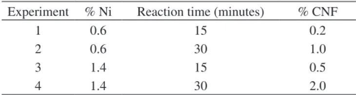
Table 1. Nickel percentage, reaction time and resulted CNF percentage.
Experiment % Ni Reaction time (minutes) % CNF
1 0.6 15 0.2
2 0.6 30 1.0
3 1.4 15 0.5
4 1.4 30 2.0
Figure 1. SEM images of CNF grown over the surface of carbon ibers:
a) 0.6% Ni/carbon iber after 15 minutes reaction, b) 1.4% Ni/carbon iber after 15 minutes reaction, c) 1.4% Ni/carbon iber after 30 minutes reaction.
Miranda et al.
sizing removal is necessary to avoid interference of polymeric vapor decomposition in carbon nanoiber growth while the temperature rose to 670 °C.
Figure 2a also shows that composites made with unsized carbon iber fabric and less than 1%/weight of nanoiber increases the lexural strength to 17%. The increase in the percentage of catalyst also causes loss of lexural strength. Thus, lower amounts of Ni catalyst and higher deposition times favor the growth of carbon nanoibers. The lexural modulus measured for all composites was 31.5 GPa, which means that deposition of nanoibers over the surface of carbon iber fabrics has no inluence on the lexural modulus.
Figure 2b shows results for interlaminar shear strength. It can be seen that interlaminar shear strength tends to decrease as the amount of carbon nanoiber increases in the composite. A reduction in the interlaminar shear of composites prepared with carbon nanoiber could be related to the iber/matrix interaction. Some authors claim that carbon nanoiber can act as a bridge between ibers and matrix in the composite, hindering crack propagation and increasing interlaminar shear. In the present work, pores were formed at the iber/ of the composite was observed by Scanning Electron Microscopy
(SEM LEO 440).
3. Results and Discussion
The reaction time had a great inluence on the growth of carbon nanoibers than the percentage of catalyst impregnated in the carbon iber fabric. The increase in the percentage of Ni did not improve CNF distribution over the surface of the carbon iber fabric, as can be seen in Figure 1a, b. Comparing Figures 1b, c, it can be seen that reaction time (growing of CNF) favored the distribution of CNF over the surface of the carbon iber fabric due to the tip growth type
mechanism15.
A lower percentage of catalyst tends to reduce the dispersion of Ni metal, giving rise to more metal particles over the carbon iber fabric surface which leads to carbon nanoiber entanglements (Figure 1b).
Figure 2 shows results of lexural strength for the composites prepared according to Table 1. Composite were prepared with as-received carbon fiber fabrics and with unsized carbon fiber fabrics (heat treated for sizing removing), for comparison purposes. The heat treatment removes the sizing, leading to composites with lower lexural strength in relation to the pristine ones. However,
Figure 2. a) Flexural strength for CF/CNF iber composite using different
manufacturing cycles. b) Interlaminar shear strength for CF/CNF composite using different manufacturing cycles.
Figure 3. SEM image of pore formation at the CNF/carbon iber composite interface.
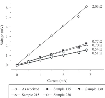
Figure 4. Voltage as a function of electric current for several CNF percentages
in the composite.
Evaluation of Carbon Fiber Composites Modiied by in Situ Incorporation of Carbon Nanoibers
4. Thostenson ET, Li WZ, Wang DZ, Ren ZF and Chou TW. Carbon nanotube/carbon iber hybrid multiscale composites. Journal of Applied Physics. 2002; 91(9):6034-6037. http://dx.doi.org/10.1063/1.1466880 5. Coleman JN, Khan U, Blau WJ and Gun’ko YK. Small but strong:
A review of the mechanical properties of carbon nanotube-polymer
composites. Carbon. 2006; 44(9):1624-1652. http://dx.doi.org/10.1016/j.
carbon.2006.02.038
6. Qian H, Greenhalgh ES, Shaffer MSP and Bismarck A. Carbon
nanotube-based hierarchical composites: A review. Journal of Materials Chemistry. 2010; 20(23):4751-4762. http://dx.doi.org/10.1039/c000041h
7. Ma PC, Siddiqui NA, Marom G and Kim JK. Dispersion and functionalization of carbon nanotubes for polymer-based nanocomposites: A review. Composites Part A: Applied Science and Manufacturing. 2010;
41(10):1345-1367. http://dx.doi.org/10.1016/j.compositesa.2010.07.003
8. Gojny FH and Schulte K. Functionalisation effect on the thermo-mechanical behavior of multi-wall carbon nanotube/epoxy-composites. Composites Science and Technology. 2004; 64(15):2303-2308. http://dx.doi.org/10.1016/j.compscitech.2004.01.024
9. Kim JA, Seong DG, Kang TJ and Youn JR. Effects of surface modiication
on rheological and mechanical properties of CNT/epoxy composites. Carbon. 2006; 44(10):1898-1905. http://dx.doi.org/10.1016/j.
carbon.2006.02.026
10. Evora MC. Effect of electron beam radiation on the surface and bulk morphology of carbon nanofibers. [Tese]. Ohio: University of Dayton;
2010.
11. Rana S, Alagirusamy R and Joshi M. A review on carbon epoxy
nanocomposites. Journal of Reinforced Plastics and Composites. 2009;
28(4):461-487. http://dx.doi.org/10.1177/0731684407085417
12. Lacerda KA. Materiais compósitos baseados em nanotubos de carbono para o setor aeroespacial. [Tese]. Ouro Preto: Universidade Federal de Ouro Preto; 2010.
13. Spitalsky Z, Tasis D, Papagelis K and Galiotis C. Carbon nanotube-polymer composites: Chemistry, processing, mechanical and electrical
properties. Progress in Polymer Science. 2010; 35(3):357-401.
http://dx.doi.org/10.1016/j.progpolymsci.2009.09.003
14. Garcia EJ, Hart AJ and Wardle BL. Long carbon nanotubes grown on the surface of ibers for hybrid composites. AIAA Journal. 2008;
46(6):1405-1412. http://dx.doi.org/10.2514/1.25004
15. Phamm-Huu C, Vieira R, Louis B, Carvalho A, Amadou J, Dintzer T et al. About the octopus-like growth mechanism of carbon nanofibers over graphite supported nickel catalyst. Journal ofCatalysis. 2006;
240(2):194-202. http://dx.doi.org/10.1016/j.jcat.2006.03.017
16. Zou G, Zhang D, Dong C, Li H, Xiong K, Fei L et al. Carbon nanoibers: Synthesis, characterization, and electrochemical properties. Carbon.
2006; 44 (5):828-832. http://dx.doi.org/10.1016/j.carbon.2005.10.035 17. Lim CS, Rodriguez AJ, Guzman ME, Schaefer JD and Minaie B.
Processing and properties of polymer composites containing aligned functionalized carbon nanoibers. Carbon. 2011; 49(6):1873-1883. http://dx.doi.org/10.1016/j.carbon.2011.01.010
18. Choi YK, Sugimoto KI, Song SM, Gotoh Y, Ohkoshi Y and Endo M.
Mechanical and physical properties of epoxy composites reinforced by vapor grown carbon nanoibers. Carbon. 2005; 43(10):2199-2208. http://dx.doi.org/10.1016/j.carbon.2005.03.036
19. Gulijk C, Lathouder KM and Haswell R. Characterizing herring bone
structures in carbon nanoibers using selected area electron diffraction and dark field transmission electron microscopy. Carbon. 2006;
44(14):2950-2956. http://dx.doi.org/10.1016/j.carbon.2006.05.036
20. Tzeng SS, Hung KH and Ko TH. Growth of carbon nanoibers on activated carbon iber fabrics. Carbon. 2006; 44(5):859-865. http://dx.doi. org/10.1016/j.carbon.2005.10.033
matrix interphase (Figure 3) and they were due to the low wettability of the epoxy resin matrix over the CF/CNF fabric. Moreover, the epoxy matrix exhibited low interdiffusion in the carbon nanoiber agglomerates, leading to the formation of pores. These pores have an adverse inluence on mechanical properties of composites as a whole. On the other hand, composites made with CF/CNF have unique electrical behavior. Figure 4 shows results for voltage as a function of current for composites prepared according to Table 1. The results show that composites made with the as-received carbon iber have the highest electrical resistance at room temperature. On the other hand, the higher the content of carbon nanoiber in the composite, the lower is the electrical resistance of the material is. Electrical conductivity
of the composite can be enhanced fourfold in relation to the pristine
carbon iber composite just by adding only 1%/weitght of CNF to it. Moreover, data from Figure 4 converted to surface electrical resistivity (sheet resistance) can result in values of 0.035 Ω for composite specimens having 1% CNF/weight. Amounts higher than 1% CNF/weight do not have a signiicant cost/beneit ratio and can
lead to losses in composite mechanical properties.
4. Conclusions
Composite materials can be made from carbon nanoibers (CNF) by in situ incorporation of over carbon iber fabrics through the CVD method, by controlling the percentage of impregnated catalyst and
reaction time.
Up to 1% CNF/weight can enhance lexural strength of the composite by 17% when CNF is deposited over non-sized carbon iber fabric. However, incorporation of CNF on composites made of carbon iber/epoxy can reduce the interlaminar shear. In general, mechanical properties of composites containing CNF can be inluenced by micropore formation at the iber/matrix interface due to the low diffusion of epoxy resin in the CNF agglomerate network. Matrix to iber interaction is a key factor for composite performance and this issue has to be addressed for future works.
In situ incorporation of CNF over carbon iber fabric increases the electrical conductivity of composite material made with up to fourfold in relation to the pristine carbon iber composite, which suggests application of this material for electrical discharge dissipation.
Acknowledgements
The authors would like to thank FAPESP, Brazil, for support and inancial resources.
References
1. Hussain F, Hojjati M, Okamoto M and Gorga R. Polymer-matrix
nanocomposites, processing, manufacturing, and application: An overview. Journal of Composite Materials. 2006; 40(17):1511-1575. http://dx.doi.org/10.1177/0021998306067321
2. Thostenson ET, Ren Z and Chou TW. Advances in the science and technology of carbon nanotubes and their composites: A review. Composites Science and Technology. 2001; 61(13):1899-1912. http://dx.doi.org/10.1016/S0266-3538(01)00094-X
3. Tai NH, Yeh MK and Liu JH. Enhancement of the mechanical properties
of carbon nanotube/phenolic composites using a carbon nanotube network
as the reinforcement. Carbon. 2004; 42(12-13):2774-2777. http://dx.doi. org/10.1016/j.carbon.2004.06.002