ABSTRACT: Carbon iber/phenolic resin composites have long been used as ablative materials in rocketry. Ablation is a complex multiscale problem where radiative and convective heating leads to the pyrolysis of phenolic resin matrix, resulting in the formation of a porous insulation char as thermal protection. This study investigates the shear properties evolution during the heat treatment of a carbon iber/phenolic resin nozzle extension entrance (exit cone) which is part of an integrated nozzle of launching and sounding vehicles, developed at the Instituto de Aeronáutica e Espaço (SP), Brazil. Specimens of the material (carbon iber/phenolic resin composite) were subjected to heat treatment at 500, 1,000, 1,500 and 2,000°C, and measurements of shear strength and shear modulus were performed using the Iosipescu mode. Experimental data were compared with the results obtained theoretically. Also, morphological analysis was accomplished by optical microscopy and the observation of fractured surfaces, by scanning electron microscopy. Signiicant morphological changes in the microstructure after heat treatments were observed. The lowest value for shear strength obtained experimentally was 4.05 MPa, which is greater than the ultimate value obtained analytically (2.35 MPa), fulilling its structural function during the propulsion time.
KEYWORDS: Ablation, Carbon-phenolic, Shear strength.
Shear Properties of Carbon Fiber/Phenolic
Resin Composites Heat Treated at High
Temperatures
Homero Paula Silva1, Luiz Cláudio Pardini2, Edison Bittencourt3
INTRODUCTION
he state-of-the-art thermal protection systems are based either on ablative or reusable material depending mainly on the mission and trajectory characteristics. hese include mainly bulk carbon, ceramics, carbon/ceramic composites and ceramic matrix composites eventually coated with refractory materials such as HfC, ZrC, and SiC. Also ablative systems based on organic polymer matrices are used as thermal protection structures (Almeida 2007; Tick et al. 1965).
he launching and sounding vehicles are important devices for research and practical and commercial use of space. hey represent the transport system by which satellites, human beings and inhabited stations are placed into Earth’s orbit. Additionally, microgravity experiments are conducted inside and outside the Earth’s atmosphere and missions to space exploration (Gonçalves 2008). In all the space vehicles used as space devices a thermal protection system is needed in order to protect the structure systems, as well as the electrical system and the payload (Dias 2001).
Many components and integrated systems of launching vehicles are manufactured in composites in order to meet 2 basic design requirements for space vehicles that are stifness and mechanical strength combined with low weight and heat resistance (Savage 1993). Besides, mass reduction for components such as fairing, ins and motor cases is critical since they represent an increase in payload (Barbosa 2004; Martins 2014).
he landmark of thermal protection systems used in rocketry are based on carbon iber/phenolic resin composites due to their exceptional ablative properties, light weight and adequate
1.Departamento de Ciência e Tecnologia Aeroespacial – Instituto de Aeronáutica e Espaço – Divisão de Mecânica – São José dos Campos/SP – Brazil. 2.Departamento de Ciência e Tecnologia Aeroespacial – Instituto de Aeronáutica e Espaço – Divisão de Materiais – São José dos Campos/SP – Brazil. 3.Universidade Estadual de Campinas – Faculdade de Engenharia Química – Departamento de Tecnologia de Polímeros – Campinas/SP – Brazil.
Author for correspondence: Homero Paula Silva | Departamento de Ciência e Tecnologia Aeroespacial – Instituto de Aeronáutica e Espaço – Divisão de Mecânica | Praça
Marechal Eduardo Gomes, 50 – Vila das Acácias | CEP: 12.228-904 – São José dos Campos/SP – Brazil | Email: [email protected]
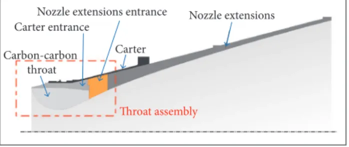
strength ater char formation (Williams and Cury 1992; Nichols and Hall 1988a,b; Hall 1988a,b). Some of these items made of composites for launching vehicles are exposed during a certain period of time under extreme temperature excursions (above 1,000 °C) and to high-speed gas low (Mach 3), as is the case of the nozzle extension (exit cone), shown in Fig. 1. he exit cone is the region of the nozzle where gas lows from the propellant burning. Usually, these parts are exposed to temperatures from 2,000 to 3,000 °C, which exceeds by far the working service limit of conventional alloys (Silva 2015).
Typical ablative materials properties, based on phenolic resin/carbon iber, phenolic resin/silica iber and polyamide/ phenolic composites are shown in Table 1. he table shows that low density and signiicant insulation properties are displayed by the polyamide/phenolic composite, while outstanding ablative eiciency is presented by the carbon iber/phenolic composite.
In a typical design of rocket nozzles, diferent components and parts having specific functions constitute the “throat assembly”, namely, carter entrance, nozzle extension entrance and throat, as shown schematically in Fig. 1.
All these mechanical parts are it and assembled together by structural bonding. he carter entrance and nozzle extension entrance are manufactured of a carbon iber/phenolic resin composite by hot-pressing process. he main throat region is made of carbon iber reinforced carbon composite. During the burning time, wear produced by the gas low associated with the heat generation and propagation through the structure (ablation phenomena) in the nozzle extension entrance afects mechanical and thermal properties weakening the overall attachment area. his can result in throat expulsion resulting in mission failure.
This study aims to evaluate the loss of shear strength of carbon iber/phenolic composites extracted from nozzle extension entrance material as a function of heat treatment temperature. he reduction in shear properties is critical since composites are laminar and prone to failure by delamination. Also the resulting morphological changes were observed by optical microscopy and scanning electron microscopy (SEM).
EXPERIMENTAL
MATERIALS
Composites were made at Plastlow Ltda. he carbon iber fabric used is rayon based, T22R-ECHO, having a iber density of 1.55 g·cm–3. he fabric has a thickness of 0.45 mm, weave Figure 1. Nozzle and throat assembly in detail.
Nozzle extensions Nozzle extensions entrance
Carter Carter entrance
hroat assembly Carbon-carbon
throat
he heat absorbed by the composite structure (carbon iber/ phenolic resin) causes endothermic processes because the area in contact with the gas low undergoes a pyrolysis process. To this phenomenon is given the name of ablation (Barbosa 2004; Minges 1969).
he composites used as thermal protection systems have to present high heat capacity to dissipate heat per unit mass (Nichols and Hall 1988a,b; Barbosa 2004). Among the composites that meet these requirements carbon iber/phenolic resin (CFPR) composites play a major role (Pardini and Levy Neto 2006; himoteo 1986). he choice of phenolic resin as matrix structure is because it has high carbon yield content when subjected to pyrolysis. he porous carbon residue structure obtained during the ablation process is a result of absorbed heat and protects the structural elements (Silva 2015).
Composite Density (g·cm–3) Ablative eficiencya (MJ·kg–1) Insulation indexb (s)
Carbon iber fabric (65%/weight) /
phenolic resin (35%/weight) 1.39 160c 30 Silica iber fabric (65%/weight) /
phenolic resin (35%/weight) 1.55 27c 65 Polyamide (50%/weight powder)/phenolic resin
(25%/weight)/25% (phenolic microballons) 0.59 35d 258 Table 1. Protective eficiency of representative composite ablators.
aHeat of ablation; bTime for back wall to reach 150 oC ; cStagnation enthalpy = 21.6 MJ
pattern of 2 × 2 Twill, and areal weight of 350 ± 35 g·m–2. A phenolic resin resol type matrix with a viscosity of 1,000 cPs at 20 °C has been used. he “prepregging” process was carried out at the Plastlow facilities. Ater wetting, the percentage iber weight reached 55 – 60%.
METHODOLOGY
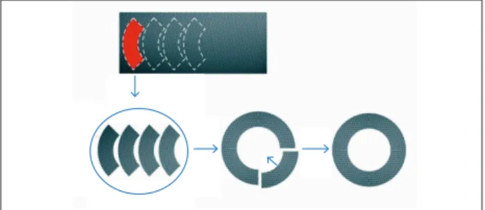
he prepregged fabrics were cut in the form of “petals” and arranged on the base of a ring-shape metallic mold so that the splices are lagged during stacking of the layers, as shown schematically in Fig. 2.
way, the test coupon comprises stacked carbon iber fabric layers. Samples were subjected to heat treatments (500, 1,000, 1,500 and 2,000 °C) in an electric furnace under inert nitrogen atmosphere. Heat treatment gradually converts the phenolic resin matrix to a carbon matrix completely at 1,000 °C.
Five specimens were tested for each temperature level. he specimens (S) were identiied according to the respective temperature level, as-moulded, S500, S1000, S1500 and S2000. he heating rate used was 2 °C·min–1 up and hold for 1 min at each temperature. he mass loss was monitored by weighting the sample before and ater heat treatment, using a precision scale METLER® PB 8001 model.
he specimens have been inally machined in the dimensions according to ASTM D5379/A 5379M-93. he test ixture and the strain gages positions attached to the samples for measuring shear strain are shown in Fig. 4.
SG1 (+45o)
SG2 (–45o)
Figure 2. Scheme of carbon iber “prepregged petals” arranged in the ring shape for lay-up molding.
The mold is then closed and the material (carbon fiber impregnated with phenolic resin) is cured by hot molding process, using a hydraulic press with a capacity of 200 tons provided with 2 platforms heated by means of electric resistors, coupled to 2 temperature controllers (a controller for each platform). he cure cycle is 2 h at 100 °C, 2 h at 120 °C, 2 h at 140 °C and 30 h at 165 °C under a pressure of 7 MPa. he material is released from the mold and the rough geometry is called “blank”.
he test specimens were extracted from the nozzle extension entrance. Twenty-five specimens were trimmed from the “blank” piece, as shown schematically in Fig. 3, to approximate dimensions of 22 mm (height), 77 mm (length), and 4 mm (thickness). Samples were taken in radial direction from the inner surface of the blank piece, as shown in Fig. 3. In this
Specimen
Figure 3. Scheme from molding the nozzle extension entrance blank and cutting the Iosipescu specimens.
Figure 4. (a) Iosipescu ixture and sample attached to it for testing; (b) Positioning of strain gages in the sample geometry.
The standard ASTM D5379/A 5379M-93 defines the Iosipescu shear strength, calculated according to the equation:
(a) (b)
(1)
(2) where: τ is the ultimate shear stress, in MPa; P
max is the
maximum load failure, in N; l represents the width of the
specimen between the roots of slots, in mm; e is the thickness
of the specimen, in mm. he shear modulus (G
12) was calculated from the stress/ strain curves, and the strains were measured using strain gages positioned at the central region of the specimens, as shown in Fig. 4b. It can be calculated according with the equation (ASTM D5379/A 5379M-93):
where: G
12is the shear modulus of elasticity, in GPa; Δ
the range of shear stress between 2 predetermined points in MPa; ΔY is the strain range between 2 predetermined points,
in μm·m–1.
he correspondent strain to stress value in a predetermined point (i) is given by the sum of the strain in modulus recorded
by the strain gages. In this case,
(t = 60 s) of a typical nozzle element used in solid rocket motor of
brazilian lauchers (Machado 1990).
where: Y
i is the shear strain at data point i; SG1i (+45°)
represents the strain measurement in the +45° positioned strain gage at the point i; SG2
i (−45°) represents the strain
measurement in the ‒45° positioned strain gage at the point i.
he tests were carried out in a universal testing machine ZWICK 1474 model with a load cell of 2,500 kg coupled to a computer which graphically process the stress/strain curves. he test speed was 2 mm·min–1.
he unheated samples and the thermally treated ones were analyzed by the Zeiss Axio Imager A2m optical microscopy. Cross-sections of these samples were prepared according to standard polishing procedures. he evaluation of the porosity was performed by using the Image J software. The image processing consisted of the following steps: (1) adjusting the contrast; (2) conversion to 256 shades of gray; (3) adjustment “threshold”; (4) measurement of the pore volume. his technique consists in converting the image obtained in 256 levels of gray and to determined value chosen, converts the tones below this value in black and above this value in white (Von Dollinger
et al. 2014). SEM was carried out in a Zeiss Leo 435VPi.
Analysis of thermal and mechanical stresses caused by temperature excursion along with the pressure exerted by the gas low during burning time has been presented by Teixeira
et al. (2007). he mechanical stresses analyzed were tensile
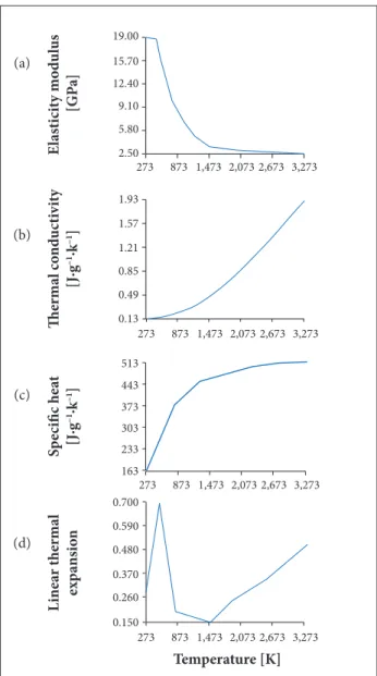
and compressive. In this study, the same model was used to evaluate the shear stresses under the same conditions considered in the previous research. he input data for this analysis were taken from carbon fiber/phenolic properties as a function of temperature (Ramesh Kumar et al. 2005), as shown in
Fig. 5. An axisymmetric model has been used, which gives the distribution of temperatures and stress. Two-dimensional plane elements with 2 degrees of freedom per node for structural analysis (PLANED2D) to 3,056 nodes and 3,033 elements have been considered.
he physical properties used in the analysis were the maximum value obtained in the extreme conditions during burning time
E las ti ci ty mo d u lus [GP a] The rma l c o nd u ct iv it y [J∙g –1∙k –1] S p ecifi c he at [J∙g –1∙k –1] L ine ar the rma l exp ans io n 19.00 15.70 12.40 9.10 5.80 2.50 1.93 1.57 1.21 0.85 0.49 0.13 163 0.150 0.260 0.370 0.480 0.590 0.700 233 303 373 443 513 Temperature [K] 273 873 1,473 2,073 2,673 3,273 273 873 1,473 2,073 2,673 3,273 273 873 1,473 2,073 2,673 3,273 273 873 1,473 2,073 2,673 3,273
Figure 5. Carbon/phenolic properties as a function of the temperature. (Ramesh Kumar et al. 2005).
(3)
RESULTS AND DISCUSSION
Table 2 shows the weight loss percentage for the specimens as a function of the heat treatment temperature. Until 1,000 °C the composite mass loss increases as the heat treatment temperature rises, due to pyrolysis of the phenolic resin. Above 1,000 °C, there was no signiicant increase in mass loss because all phenolic resin of the composite has been carbonized, occurring only oxidation of the carbon ibers.
(a)
(c) (b)
he results of the Iosipescu shear strength and shear modulus tests for the composite samples are shown in Table 3. The results show that a reduction in shear strength occurs as heat temperature goes up to 2,000 °C. Signiicant reduction in shear strength is noted ater 1,000 °C heat treatment. Shear modulus, contrarily, increases as heat treatment temperature goes up to 2,000 °C. hese changes are due to progressive pyrolysis of phenolic resin turning on glassy carbon. Heat treatment creates a porous composite microstructure, lowering the strength, but increasing twofold the shear modulus due to the formation of stifer carbon matrix compared with phenolic resin.
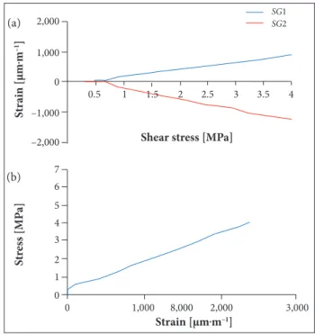
Figures 6 to 10 present the strain measurements during the Iosipescu shear test, as a function of the applied stress. Figure 6a shows the proile of strain behavior during Iosipescu shear test. Figure 6b shows the curves of shear stress as a function of the total strain (Y
i = | SG1i (+45°) | + | SG2i (−45°) |
for the as-molded carbon iber/phenolic resin composite. A characteristic non-linearity proile of the stress/strain curve is observed.
Figure 7a shows the strain as a function of shear stress for composites heat treat at 500 °C. he stress/strain curve shown in Fig. 7b has a similar proile to the carbon iber/phenolic resin composite, where a non-linearity between stress and strain is noticed. However, the strain at failure for the sample heat treated at 500 °C (~ 1.4%) is much lower than the carbon iber/phenolic resin composite (~ 2.4%). A 15%-reduction in the shear stress is found for sample heat treated at 500 °C, in relation to the pristine composite.
Figure 8a shows the strains as a function of shear stress for composites heat treated at 1,000 °C. It can be seen in Fig. 8b a quasi-linear behavior of the stress/strain curve, unlike to the previous cases. he strain levels are much lower than the as-molded sample (carbon iber/phenolic resin composite), whereas the strain gages registered a value on the order of 2,000 μm·m–1, i.e. equivalent to about 10% of deformation of the untreated sample. The ultimate shear stress showed a
Samples Weight before HT (g) Weight after HT (g) Weight loss (%)
As-molded 8.28 ± 0.25 8.28 ± 0.25 0
S500 9.30 ± 0.10 7.64 ± 0.32 8.21 ± 0.28 S1000 9.20 ± 0.30 7.14 ± 0.16 7.76 ± 0.24 S1500 9.10 ± 0.05 6.88 ± 0.02 7.56 ± 0.03 S2000 9.22 ± 0.18 6.84 ± 0.16 7.41 ± 0.16 Table 2. Weight loss of the specimens as a function of heat treatment temperature for the carbon iber/phenolic resin composite.
HT: Heat treatment.
Sample Ultimate shear
strength (MPa)
Shear modulus (GPa)
As-molded 22.5 ± 4.0 1.55 ± 0.6 S500 19.0 ± 2.7 2.69 ± 0.7 S1000 4.0 ± 0.6 3.10 ± 0.3 S1500 4.76 ± 0.3 3.85 ± 0.7 S2000 5.08 ± 0.8 2.90 ± 0.4 Table 3. Ultimate shear strength and shear modulus.
Figure 6. Shear properties for the as-molded carbon iber/ phenolic resin composites under Iosipescu loading mode.
10,000
500
0
–500
–10,000
–15,000
20
16
12
8
4
0
0 4,000 8,000 12,000 16,000
16 14 12 10 8 6 4 2
Shear stress [MPa]
Strain [μm.m–1]
S
tr
ess [MP
a]
S
tr
ain [μm.m
–1]
SG1
SG2
signiicant decrease, the result obtained is about 18% from shear stress untreated samples value, indicating the weakening of the material to 1,000 °C.
Figure 9a shows the shear strain as a function of shear stress and the shear stress as a function of shear strain for samples subjected to 1,500 °C treatment temperature. It can be seen in Fig. 9b a quasi-linear proile of the curve, similar
(a)
10,000 5,000 0 –5,000 –10,000 7 6 5 4 3 2 1 0
0 4,000 8,000 12,000 16,000
5 4 3.5 4.5 3 2.5 2 1 0.5 1.5
Shear stress [MPa]
Strain [μm.m–1]
S tr ess [MP a] S tr ai n [ μm.m –1] SG1 SG2 2,000 1,000 0 –1,000 –2,000 7 6 5 4 3 2 1 0
0 1,000 8,000 2,000 3,000
4 3.5 3 2.5 2 1 0.5 1.5
Shear stress [MPa]
Strain [μm.m–1]
S tr ess [MP a] S tr ai n [ μm.m –1] SG1 SG2 4,000 2,000 0 –2,000 –4,000 5 4 3 2 1 0
0 400 800 1,200 1,600 2,000
6 5 4 3 2 1
Shear stress [MPa]
Strain [μm.m–1]
S tr ess [MP a] S tr ai n [ μm.m –1] SG1 SG2 1,000 500 0 –500 –1,000 8 7 6 5 4 3 2 1 0
0 200 400 600 800 1,000 1,200 1,400 5 4
3 2
1
Shear stress [MPa]
Strain [μm.m–1]
S tr ess [MP a] S tr ai n [ μm.m –1] SG1 SG2
Figure 10. Shear properties for carbon iber/phenolic resin composites under Iosipescu loading mode, when heat treated at 2,000 °C.
Figure 7. Shear properties for carbon iber/phenolic resin composites under Iosipescu loading mode, when heat treated at 500 °C.
Figure 8. Shear properties for carbon iber/phenolic resin composites under Iosipescu loading mode, when heat treated at 1,000 °C.
Figure 9. Shear properties for carbon iber/phenolic resin composites under Iosipescu loading mode, when heat treated at 1,500 °C.
to the previous case. he shear behavior of composites heat treated at 1,500 °C is similar to the composites heat treated at 1,000 °C.
(a) (a) (a) (a) (b) (b) (b) (b)
Figure 11. Photomicrographs of the pristine carbon iber/phenolic resin composite.
Figure 12. Photomicrographs of the 500 °C treated samples.
of progressive heat treatment process for carbon iber/phenolic resin composites. Crack and pore formation depends on the type of carbon iber used for manufacturing the composites. Carbon iber bonding to the matrix seems to have a signiicant efect on iber/matrix and iber tow/matrix debonding either on the molding stage as well as during the excursion of heat treatment temperature. very similar to the composites heat treated at 1,000 and 1,500 °C.
However, strain for the samples heat treated at 2,000 °C is lower than the ones found for 1,000 and 1,500 °C treatments, respectively. For heat treatments beyond 1,700 °C incipient forms of crystalline domains having deined linear edges appear and favors slipping between basal planes when stress is applied, increasing the strain levels (Barbosa 2004).
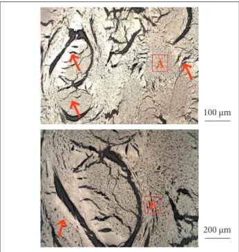
Figures 11 to 15 show photomicrographs of the pristine composite samples. In Fig. 11, micrographs of the 2 diferent regions and amplitudes from the carbon iber/phenolic resin composite, a cross section of the carbon ilaments can be identiied (position A), and iber strands in the direction parallel to the picture plane (position B). he distribution of reinforcement iber strands is not uniform and there are some regions rich in resin as well as pores and microcracks (indicated by red arrows) in between the iber tows. he positioning of the iber strands in multiple directions can further enhance strain under shear deformation.
Figure 12 shows, in 2 different regions and amplitudes, photomicrographs of 500 °C treated samples. It is possible to observe matrix-rich regions (C position) and iber-rich regions (D position). A clear debonded region in the matrix is also found, near to the iber tows (indicated by red arrows). Debonding is probably due to the contraction process, resulting from the pyrolysis process. Large microcracks are observed in the matrix region, which can be outcome from the shrinkage process during curing or even due to the poor bonding between carbon iber and phenolic resin. he weave patterns of the fabric layers are not clearly deined.
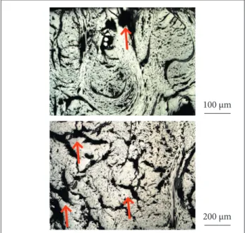
he heat treatment at 1,000 °C reveals in 2 photomicrographs taken from diferent regions and amplitudes in Fig. 13 large pores in the matrix regions (indicated by red arrows), which probably arose during pyrolysis as a result of the composite shrinkage. Similarly to Fig. 12, the iber weave array is not uniform. At this level of heat treatment (1,000 °C) the composite seems to have a large amount of damage caused by the pyrolysis process. In the photomicrographs of 1,500 °C heat treated samples, Fig. 14 shows, in 2 diferent regions and amplitude, large iber agglomerates and few resin-rich regions are seen. It is also observed microcracks throughout the composite cross section, due to composite shrinkage and weight loss during pyrolysis process (indicated by red arrows). Similarly to 1,500 °C treated samples, Fig. 15, referring to 2,000 °C treated specimens, observed in diferent regions and amplitudes, also displays few resin-rich regions and many microcracks caused by pyrolysis process (as indicated by red arrows). Signiicant amount of intra-bundle cracked regions can be seen. he formation of cracks and pores is a characteristic feature
C
D
B
A
C
100 μm 100 μm
As mentioned before, the image analysis for porosity identification was done by using optical microscopy and Image J software. The analysis is shown in Fig. 16. Given a gray scale ranging from 0 (completely black) to 255 (pure white), the threshold level which allowed for isolation of the pores was 28. That is, shades below 28 were converted to black and above the blank value (Von Dollinger et al.
2014). Table 4 presents the mean values obtained for each set of specimens.
Figure 13. Photomicrographs of the 1,000 °C treated samples.
Figure 14. Photomicrographs of the 1,500 °C treated samples.
A slight increase in the percentage porosity is noted in accordance with the treatment temperature caused by the contraction of the composite along with weight loss due to pyrolysis of the phenolic matrix.
Figure 17a shows a microfractograph of the fracture surface of the pristine carbon iber/phenolic resin composite under shear mode. A high iber concentration in the direction parallel to the picture plane (position A) is found and a detail of a iber strand in the perpendicular direction to the picture plane (position B) can also be identiied. Figure 17b shows the detail of the iber strand where a number of “bean shape” carbon iber cross section can be seen. he bean shape cross section is typical from ex-rayon carbon ibers.
he microfractographs features are not changed with the applied treatment temperatures. he images shown are typical of the material.
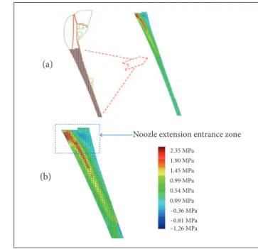
Figure 18 shows grid mesh obtained for the exit cone element and the model profile corresponding to the levels
Figure 15. Photomicrographs of the 2,000 °C treated samples.
Samples Porosity average
(%)
As-molded 21.22 ± 1.62 S500 23.43 ± 3.27 S1000 24.12 ± 2.56 S1500 26.15 ± 1.89 S2000 27.76 ± 2.88 Table 4. Percentage porosity of the specimens.
100 μm
100 μm 200 μm 100 μm
200 μm
Figure 18. (a) Proile of the nozzle with the correspondent theoretical shear stress level; (b) Color scale referred to stress levels through the nozzle geometry.
Figure 17. SEM photomicrographs of the untreated samples.
2.35 MPa 1.90 MPa 1.45 MPa 0.99 MPa 0.54 MPa 0.09 MPa –0.36 MPa –0.81 MPa –1.26 MPa
Noozle extension entrance zone (a)
(a)
(b) (b)
Figure 16. (a) Photomicrograph of a region of the sample; (b) Image from Image J treated area.
CONCLUSION
Carbon iber/phenolic resin composites were submitted to high temperature heat treatment in order to evaluate the changes in shear behavior. Heat treatment temperatures were 500, 1,000, 1,500 and 2,000 °C. In general, shear strength, measured by the Iosipescu shear mode, reduces as the temperature goes higher, whereas the shear modulus increases.
The microstructure is affected by heat treatment temperatures by the formation of a network of microcracks and pores throughout the material. The void volume percentage of the composite increases as a function of heat treatment temperature due to the weight loss from both the fiber and the resin during the pyrolysis process. These changes in the void volume influence negatively the shear strength.
he shear strength ranged from 22.43 MPa for the pristine carbon iber/phenolic resin composite to 4.05 MPa for the same composite treated between over 1,000 and up to 2,000 °C. For the shear modulus, obtained values ranged between 1.55 and 3.85 GPa by increasing the heat treatment temperature.
In general, shear tests on composite samples heat treated above 1,000 °C revealed fragile behavior of the tested material due to the formation of carbon matrix, pores and microcracks. Higher shear deformations are observed for composites heat treated at high temperatures (T > 1,500 °C), because
of shear stress. The region of the model in which the shear stress attains its maximum values is the nozzle extension entrance. The ultimate shear stress of 2.35 MPa was calculated taking the most extreme situation of propeller burning operation.
The positive and negative values in the color scale are due to the reversal of the direction of shear stress in relation to the reference which was adopted in the calculation process.
B
A
150 μm
of an incipient formation of oriented crystalline graphitic structures in the carbon matrix.
he shear stress value calculated theoretically (2.35 MPa) corresponds to ~ 58% of the minimum value obtained
experimentally in this study (4.05 MPa), i.e. it has a 1.72
of safety factor. Therefore, the nozzle extension entrance, as it is currently manufactured, fulfills the design requirements.
REFERENCES
Almeida LEN (2007) Obtenção e caracterização de compósitos ablativos de matrizes fenólica e fenólica modiicada com epóxi, com reforço de ibra de carbono picada (Master’s thesis). São José dos Campos: Instituto Tecnológico de Aeronáutica.
Barbosa CAL (2004) Obtenção e caracterização de materiais ablativos a base de compósitos de ibra de carbono/resina fenólica (Master’s thesis). São José dos Campos: Instituto Tecnológico de Aeronáutica.
Dias FMC (2001) Desenvolvimento de processos de fabricação de estruturas em material compósito ablativo para tubeiras de foguetes (Master’s thesis). São José dos Campos: Instituto Tecnológico de Aeronáutica.
Gonçalves A (2008) Caracterização de materiais termoestruturais a base de compósitos reforçados com ibras de carbono (CRFC) e carbono reforçado com ibras de silício (SiC) (PhD thesis). São José dos Campos: Instituto Tecnológico de Aeronáutica.
Hall WB (1988a) Standardization of the carbon-phenolic materials and processes. Vol. 1. Experimental studies. NASA Grant No. NAG8-545.
Hall WB (1988b) Standardization of the carbon-phenolic test methods and speciication. Vol. 2. NASA Grant No. NAG8-545.
Machado HA (1990) Análise uni-dimensional para escoamento bifásico e transferência de calor em tubeiras de foguetes a propelente sólido (Undergraduate thesis). Rio de Janeiro: Universidade Federal do Rio de Janeiro.
Martins FR (2014) Caracterização do fresamento de chapas de compósito polímero reforçado com ibras de carbono (PRFC) (PhD thesis). Campinas: Universidade Estadual de Campinas.
Minges ML (1969) Thermal physical characteristics of high-performance ablative composites. J Macromol Sci Chemistry A 3(4):613-639. doi: 10.1080/10601326908053832
Neuse EW (1973) Polymers for potential use as charring ablators under hyperthermal re-entry conditions: a review of recent developments. Mater Sci Eng 11(3):121-150. doi: 10.1016/0025-5416(73)90060-8
Nichols RL, Hall WB (1988a) Standardization of the carbon-phenolic materials and processes. Vol. 1. Experimental studies. NASA Grant No. NAG8-545.
Nichols RL, Hall WB (1988b) Standardization of the carbon-phenolic test methods and speciication. Vol. 2. NASA Grant No. NAG8-545.
Palmério AF (2013) Introdução à tecnologia de foguetes.
Pardini LC, Levy Neto F (2006) Compósitos estruturais: ciência e tecnologia. São Paulo: Edgar Blücher.
Ramesh Kumar R, Vinod G, Renjith S, Harikrishnan R (2005) Thermo-structural analysis of composite structures. Mater Sci Eng 412(1):66-70. doi: 10.1016/j.msea.2005.08.065
Savage G (1993) Carbon /carbon composites. London: Chapman & Hall.
Silva SFC (2015) Tecnologia de plasma para estudo das propriedades ablativas em compósitos obtidos por bobinagem para uso aeroespacial (PhD thesis). Campinas: Universidade Estadual de Campinas.
Teixeira HS, Silva HP, Machado HA, Shimote WK (2007) Análise termo-elástica de tubeira do 2º estágio do VLS-1. Código: 590-213100/ B0001. Relatório Técnico No. ASE-RT-007.
Thimoteo HPC (1986) Estudo do comportamento ablativo de composições fenólicas com carga (Master’s thesis). Rio de Janeiro: Universidade Federal do Rio de Janeiro.
Tick SJ, Huson GR, Griese R (1965) Design of ablative thrust chambers and their materials. J Spacecraft Rockets 2(3):325-331. doi: 10.2514/3.28179
Von Dollinger CFA, Souza WO, Pardini LC (2014) Evaluation of porosity during pyrolysis of carbon iber/phenolic resin composites. Proceedings of the 2nd Brazilian Conference on Composite Materials (BCCM 2); São José dos Campos, Brazil.