Stress wave propagation in thin long-fiber carbon/epoxy
composite panel. Numerical and experimental solutions.
T. Kroupa
a,∗, J. ˇ
Cerv
b, F. Valeˇs
caInstitute of Thermomechanics, Czech Academy of Sciences, Veleslav´ınova 11, 301 14 Plzeˇn, Czech Republic bInstitute of Thermomechanics, Czech Academy of Sciences, Dolejˇskova 5, 182 00 Praha 8, Czech Republic c
Institute of Thermomechanics, Czech Academy of Sciences, Veleslav´ınova 11, 301 14 Plzeˇn, CzechRepublic
Received 12 September 2007; received in revised form 21 September 2007
Abstract
The article deals with experimental and numerical analysis of stress wave propagation in a thin long fiber carbon/epoxy composite material. Experiments were performed on in-plane loaded square composite panels with dimensions 501mm × 501mm × 2.2mm. The panels have several fiber orientations (0◦, 30◦, 60◦ and 90◦
measured from the loaded edge). They were loaded by in-plane impact of steel sphere. The impact area was on the edge, exactly150mm from top left corners corner of the panels. The loading force was approximated by a
time dependent function. Its shape was obtained from three dimensional contact analysis, which was performed on smaller area of panel. The function was used in further plane stress analysis of the whole panels. The comparison of the numerical and experimental results was executed. An attempt at determination of velocity of propagation of Rayleigh waves on the loaded edge was performed and the results are discussed in the paper. Further directions of the research are proposed.
c
° 2007 University of West Bohemia. All rights reserved.
Keywords:FRP composite, carbon, epoxy, orthotropic, Stress wave, Rayleigh waves, FEM, numerical,
experimen-tal, impact, plane stress, in-plane loading
1. Introduction
The problem concerned with wave propagation in a long-fiber reinforced composite is dis-cussed in the paper. The considered composite material is epoxy resin (matrix) reinforced by long carbon fibers, which are systematically arranged in the matrix in specified direction. Since the fibers are systematically orientated, a composite of this kind has strong directional proper-ties, thus macroscopically for sufficiently long wavelength it can be regarded as a homogeneous anisotropic material.
The propagation of elastic waves in anisotropic media differs in many aspects from that customarily attributed to elastic waves in isotropic media. This fact is evident from results presented in e.g. [8], [9], [7] or [5]. For a given direction of waves propagation represented by a wave vector there will be generally three phase velocities [1], the three corresponding displacement (polarization) vectors will be mutually orthogonal but contrary to the isotropic
case the displacements are neither truly longitudinal nor truly transverse in character. As the mechanical or material behavior of the solid becomes more complicated, the description of non-stationary wave propagation starts to be analytically intractable and, consequently, such problems are often modeled by means of discretization techniques such as finite elements (FE) or finite differences. It is very useful to supplement the theoretical analysis by experimentally obtained results.
The main aim of the paper is to study the wave propagation in thin orthotropic laminate panel loaded in-plane by stress pulse. Experimental solution utilizes for noncontact measurements a laser vibrometer. Experiments were performed on in-plane loaded square composite panels with dimensions 501mm ×501mm× 2.2mm. Panels have several fiber orientations. They were loaded by in-plane impact of steel sphere (diameter 4mm). The impact area was on the edge, exactly150mm from to left corners of the panels.
Theoretical solution is based on FE approach. The loading force was approximated by a time dependent function. Its shape was obtained from three dimensional contact analysis, that was performed on smaller area of the panel with fiber direction0◦. The function was used in further
plane stress analysis of the whole panels with all of the fiber orientation mentioned above. This was performed this way with the aim to investigate and show wether the shape of loading force depends on the fiber orientation. The comparison of the numerical and experimental results was performed and is discussed in the paper.
2. Problem formulation
Let us consider a thin unidirectional fiber-reinforced composite panel. It is also assumed that fiber diameters and thickness of the composite panel are small compared to the shortest wavelength taken into account. Hence one can consider the material as orthotropic in the state of plane stress. The principal directions of orthotropy often do not coincide with coordinate directions that are geometrically natural to the solution of the problem. Therefore it is assumed that body axesx,yform a nonzero angleαwith principal material axesL,T as may be seen in fig. 1. Third axisz is identical with material axisT′ and constitutes axis of rotation of principal
The stress-strain relation for plane stress in principal material axesL, T can be written in the form [4]
σL σT τLT =
C11 C12 0 C12 C22 0
0 0 C66
· εL εT γLT
, (1)
where matrix elements Cij depend on Young’s moduli and Poisson’s ratios (for explicit
ex-pressions see e.g. [4]), σL, σT and τLT are normal stresses and shear stress in material axes
coordinate system and εL, εT andγLT strains and shear strain also in material axes coordinate
system. Stress-strain relation inx,ycoordinate system can be written in the form
σx σy τxy =
Q11 Q12 Q16 Q12 Q22 Q26 Q16 Q26 Q66
· εx εy γxy
, (2)
where matrix elements Qij depend on elements Cij and fiber direction angle α (for further
details see e.g. [4]). The displacement equations of motion in the absence of body forces are [9]
Q11 ∂2
u
∂x2 + 2Q16 ∂2
u
∂x∂y +Q66 ∂2
u ∂y2 +Q16
∂2 v
∂x2 + (Q12+Q66) ∂2
v
∂x∂y +Q26 ∂2
v ∂y2 =ρ
∂2 u ∂t2, (3)
Q11 ∂2
v
∂y2 + 2Q16 ∂2
v
∂x∂y +Q66 ∂2
v
∂x2 +Q16 ∂2
u
∂x2 + (Q12+Q66) ∂2
u
∂x∂y +Q26 ∂2
u ∂y2 =ρ
∂2 v ∂t2. (4) wheretstands for time,uandvare displacements in the axesxandyrespectively,ρis material density.
The material consists of carbon fibers and epoxy matrix as was proposed above. It is usual, that material constants gained from manufacturer are not accurate [6], therefore they must be modified. The modified material constants were obtained by comparison with one set of exper-imental data. Both sets of material constants are shown in the tab. 1.
In the case of plane stress and for a given direction of wave propagation there will be two phase and at least two group velocities. Values of the phase velocities of quasi-longitudinal and quasi-transverse waves, which propagate in the direction parallel to the loaded edge of the panel with fiber direction0◦ are shown in the 1. These values can be obtained from explicit relations
cL = s
EL
ρ(1−ν2
LT ET EL)
, (5)
cT = s
GLT
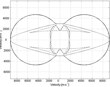
The fig.2 and fig.3 show phase and group velocity curves for both sets of mechanical con-stants of unbounded orthotropic material.
Fig. 2. Phase (black) and group (gray) velocities for manufacturer’s material constants (quasi-longitudinal - solid line, quasi-transverse - dashed line).
Fig. 3. Phase (black) and group (gray) velocities for modified material constants (quasilongitudinal -solid line, quasi-transverse - dashed line).
Special type of waves, so called Rayleigh waves, propagates closely to the loaded edge of the material. This type of waves can be located closely to the free edge of the material and it vanishes with the increasing distance from the loaded edge. The velocities of the Rayleigh waves for the cases of loaded panels with fiber directions0◦and90◦are also shown in the tab. 1.
constant manufacturer’s modified velocities manufacturer’s modified EL 129.9GPa 113.8GPa cL 9223ms−
1
8622ms−1 ET 13.9GPa 8.8GPa cT 1709ms−
1
1765ms−1 GLT 4.5GPa 4.8GPa cR-0◦ 1699ms−
1
1745ms−1 νLT 0.28 0.28 cR-90◦ 1695ms−
1
1726ms−1
Tab. 1. Material constants and wave velocities.
3. Experiment
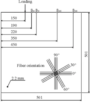
The dimensions of the whole measured panels, thickness, loading and measuring pointsa40, a70,a200,a300and fiber orientations of the composite panels are shown in the fig. 4.
Fig. 4. Composite panel.
The Compact Laser Vibrometer 2000 (CLV) was used to measure velocities at selected points located on the loaded edges of the composite panels. The edges were loaded by in-plane impact of steel sphere with (diameter4mm) that was attached on the double sling and released from known height. The incident velocity of the sphere was calculated and used as initial condition in the FE contact analysis of the steel sphere impact on the edge of the composite sample with smaller dimensions and with fiber direction 0◦. Smaller dimension of the sample
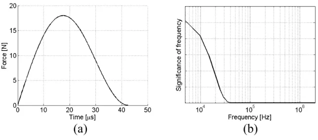
Fig. 5. Loading force (a) and its frequency spectrum (b).
4. Numerical analysis
Maximal significant frequency of the loading is fmax = 44kHz. It is necessary to use
well sized elements to suppress the dispersion on the FE grid. Four node square elements with the edge length aM KP = 2.004mm were employed in the presented work. It turned out that
it was sufficient dimension of elements for analyses with both sets of mechanical constants. Considering the minimal wave lengthλmin = 10·aM KP for which is FE grid able to transfer
signals with low influence of the dispersion we can calculate maximum admissible frequency from the relation
νmax =
cT
λmin
(7)
and maximal time increment as
△t≤ aM KP
cL
. (8)
Tab.2 shows the parameters of FE net for both sets of material constants.
paramater manufacturer’s modified
νmax 85.3kHZ 88.1kHz △t 0.217µs 0.232µs
Tab. 2. Parameters of the simulations.
force becomes thinner and has greater amplitude. All numerical analyses were performed with use of loading force obtained from contact analysis of panel with fiber angleα= 0◦.
5. Conclusion
The experimental and numerical solutions of the stress wave propagation problem in thin unidirectional long-fiber composite panel were obtained. Results of both approaches have been compared mutually and sufficient agreement has been found. On the contrary, certain inter-esting and important problems have appeared. The numerical results obtained with the use of the modified material constants still show minor differences compared to those gained by ex-periment and theory. Therefore the program for precise evaluation the velocity cR from the
numerical results was developed. It shows the difference about 1% against values of cR
ob-tained by analytical method. This discrepancy can be caused by grid dispersion or by choosing a big time increment etc. It will be subjected to further analysis. Also, it is very difficult to specify value of cR from the experimental results with sufficient accuracy due to oscillations
of signal. This can be caused by imperfection of the experimental devices or by the influence of the disturbances of the surroundings when performing the experiment. And so one of the main aims for the next research will be the development of program that will be able to spec-ify values of cR from experiments more accurately. The next aim of the further research will
be the investigation of the influence of dispersion on the accuracy of the numerical solution of Rayleigh wave propagation in comparison with analytically obtained values ofcR and precise
determination of velocitycRfor composite materials with various fiber orientations.
Acknowledgements
The work has been supported by the grant project GA AS CR no. A200760611.
References
[1] S. Abrate, Impact on composite structures, Cambridge university press, 1998.
[2] J. ˇCerv, Rayleigh (Edge) Waves in a Thin Orthotropic Semi-Infinite Laminate, Proceedings of Eleventh International Congress on Sound and Vibration, 5-8 July 2004, St. Petersburg, Russia, pp. 3519-3526.
[3] J. ˇCerv, R-Waves in Thin Specimens Made of Laminates or Some Anisotropic Metals, Proceedings of the International Scientific Conference, Session 8 - Applied Mechanics, September 7-9, 2005, Ostrava, Czech Republic, pp. 253 - 256.
[4] R. M. Jones, Mechanical of Composite Materials, Scripta Book Company, Washington, D.C., 1975.
[5] T. Kroupa, J. ˇCerv, V. Laˇs, Vlny napˇet´ı v tenk´em p´asu s obecnou ortotropi´ı, Proceedings of Com-putational mechanics 2004, Neˇctiny, Z ˇCU Plzeˇn, Czech Republic, 2004.
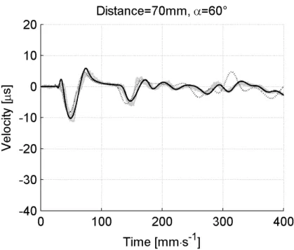
Fig. 6. FEM (black - modified, black dashed - manufacturer’s constants) and experimental (grey).
Fig. 8. FEM (black - modified, black dashed - manufacturer’s constants) and experimental (grey).
[7] T. Kroupa, R. Zemˇc´ık, V. Laˇs, Progressive failure analysis of orthotropic plate loaded by transverse low-velocity impact, Proceedings of 5th Inernational Congress of Croatian Society of Mechanics, Trogir/Split, Croatia, 2006.
[8] R. Zemˇc´ık, J. ˇCerv, V. Laˇs, Numerical and experimental investigation of stress wave propagation in orthotropic strip, Proceeding of Computational Mechanics 2003, Neˇctiny, Z ˇCU Plzeˇn, 2003. [9] R. Zemˇc´ık, Non-stationary progressive failure analysis of fiber-reinforced composites, Disertation