Luiz Magalhaes1,2 and Robin Kravets1
1Department of Computer Science
University of Illinois, Urbana-Champaign 1304 W Springfield Avenue
Urbana, IL 61801 {magalhae,rhk}@cs.uiuc.edu
2Departamento de Engenharia de Telecomunicações
Universidade Federal Fluminense Rua Passo da Pátria 156
Niterói – RJ Brasil [email protected]
Abstract
This paper presents a framework for the creation of trans-port protocols for mobile hosts that use multiple link lay-ers simultaneously for the same connection. This abstrac-tion provides an end-to-end transport layer channel be-tween two applications that do not have to be aware of host mobility. The channel is composed of multiple net-work layer sub-channels. A sub-channel is an end-to-end network layer connection that is mapped to one physical interface. Inverse multiplexing is used at the transport level to divide application data into sub-channels, and a rate-based transmission mechanism provides congestion avoidance. The same mechanism is used to differentiate transmission losses from congestion losses, resulting in good throughput in lossy wireless links. Experimental re-sults for two protocols created using this framework vali-date our design choices.
Keywords: transport protocols, mobility, inverse multi-plexing, wireless, rate-based
1
Introduction
Current generation mobile hosts have multiple built-in net-work interfaces and the capacity for expansion. Many competing infrastructures for wireless network access are being deployed. The current state-of-the-art in mobile net-working allows the use of multiple network technologies, but only one at a time [1, 2]. This results in an environ-ment that can be connectivity rich, but in which hosts have limited access to resources. Wireless technologies tend to offer lower bandwidth than their wired counterparts. Therefore, to many mobile hosts the bottleneck link is the last hop. The lowest bandwidth link is the link from the network access point to the mobile host. By extending the current technology to encompass the simultaneous use of multiple interfaces, mobile hosts can access the full band-width available in an environment.
Multiplexing is a very well understood communication technique for transmitting multiple streams through a sin-gle interface. Demultiplexing is the technique to recover a stream from the aggregated flow. Multiplexing and demul-tiplexing are used, for example, to send multiple TCP flows through a single IP interface. The port number con-tained in the TCP header is used for demultiplexing the aggregated TCP streams, in order to deliver data to the right application. Inverse multiplexing is used to transmit a single stream through multiple interfaces. ATM uses in-verse multiplexing [3] to aggregate fractionary interfaces into a single interface with higher bandwidth. This type of bandwidth aggregation can also be found in the Internet’s link layer [4, 5]. The current techniques limit aggregation to links of the same technology between the same end-points.
This paper presents a novel technique for using inverse multiplexing for aggregating bandwidth from heterogene-ous network interfaces. Inverse multiplexing can be used with very good results for increasing the bandwidth avail-able to hosts when their bottleneck link is located at the
last hop. Our channel abstraction is based on inverse
mul-tiplexing. A channel is an end-to-end transport layer
con-nection. We use inverse multiplexing to create a single
end-to-end channel from multiple sub-channels,
end-to-end network layer connections over heterogeneous link
layer interfaces. The transport layer has to be link-layer
aware to be able to make use of multiple heterogeneous
link layers. To make the channel more useful to mobile
hosts, we added mechanisms to deal with the loss charac-teristics of wireless links to the transport protocols that
implement the channel. Finally, the channel mechanism
offers a path for end-to-end mobility [6], because a side effect from multiplexing is the uncoupling of the transport layer from the network layer.
band-width from multiple heterogeneous link layers, by using end-to-end inverse multiplexing. The mechanisms used for inverse multiplexing are well suited to wireless envi-ronments and allow simple host mobility, using the IP in-frastructure already deployed.
The remainder of this paper is organized as follows. In the next section, we present the motivation for bandwidth ag-gregation and the reasons for inverse multiplexing. The availability of multiple interfaces and the lack of way to exploit the additional bandwidth led to the creation of a transport layer solution. The architecture of this solution is presented in Section 3. The mechanisms used for imple-menting the architecture, and the adaptation to wireless links is presented on Section 4. We designed a suite of
protocols that share the channel architecture. We present
the suite and experimental results from the implementation of two protocols, Multimedia Multiplexing Transport Pro-tocol (MMTP [7]) and Reliable Multiplexing Transport Protocol (RMTP) in Section 5. The last Section contains conclusions and future research.
2
Motivation
Mobile computing devices are becoming as common as their stationary counterparts, and the trend points to an enormous growth in the number of mobile hosts. In the same way the capability of a personal computer is in-creased with its connection to a network, the potential of mobile devices is increased with network connectivity. Thus, there is a clear need to provide network access to mobile computing devices. In response, infrastructure has been built to provide connectivity to mobile devices, rang-ing from CDPD networks that offer 19.2Kbps to the newly announced initiative of airports [8] and even a coffee shop chain [9] to offer 11Mbps IEEE 802.11 network access to its users. Infrastructure deployment for each technology is not continuous. The coverage area of each base-station forms isolated areas where is possible to communicate us-ing that technology, creatus-ing islands of connectivity for that technology. The different technologies often have overlapping coverage areas. As more base stations are in-stalled, the number of islands of connectivity increases. Such increases may cause islands from the same technol-ogy to merge, and islands from different technologies to overlap.
2.1
Host Mobility
The user of a mobile device has some choices in regard to maintaining connectivity while moving. One choice is to use a link-layer mobility solution, like a CDPD network or a cellular modem. In this case, the link layer provides the
switch from one point of attachment to another as the user moves from the area of coverage of one base station to an-other. Link-layer solutions are transparent to the network and upper layers, but do not insulate the applications from variations in link quality, delays and the occasional black-out. Another choice is to use a network layer mobility so-lution. Mobile IP [10] and Mobile IPv6 [11] add the ca-pacity to use heterogeneous link layers, and can be ex-tended [1] to switch from one link layer technology to an-other in case the link layer becomes unavailable, either by a blackout or because the user moved away from the cov-erage area of that link layer. This allows the user to move from one island of connectivity to another without sever-ing transport layer connections. Network layer solutions are transparent to the transport layer. Due to this transpar-ency, transport layer connections are not aware that the sudden changes in link quality and delays may be caused by a switch from one link layer to another (handoff). This confuses their congestion avoidance mechanism, affecting the performance of the transport layer [12].
2.2
Routing and Multihomed Mobile Hosts
The overlap of connectivity islands from multiple tech-nologies allows a mobile host to have more than one ac-cess point to the network simultaneously active. That is, a mobile host could be multihomed. This opens a new realm of possibilities for wireless mobile hosts that is rarely found in the wired world, because multihomed general purpose wired hosts are rare. Routers are multihomed by nature, but a general-purpose multihomed host requires special routing tables to exploit the potential of multiple network connections. If the host is not routing traffic, the routing tables of such host divide the network according to rules set to mirror information of, for example, reachabil-ity, performance and cost. In comparison, a wired host with a single network connection normally has a simple routing table, consisting of the loopback device, the home network and the default router. Due to the nature of net-work access points, a multihomed mobile host can poten-tially use any single network access point of any technol-ogy for all its network traffic. If the network access points of different technologies divulge routing information, the mobile can transparently choose which interface to use for each connection, by building a routing table and routing packets to each network access point according to their destination.
share of the raw bandwidth of a link that is available to new connections on that link. Because the last hop is nor-mally the link with lowest available bandwidth in the path between a mobile and another host, it will define the band-width characteristics of the connection as a whole. The characteristics of the bottleneck link, regardless of being the last hop or not, are not normally found in the routing information relayed to end-hosts, because it is dynamic and varies as routers get more or less loaded. The routing information approach would not guarantee that the mobile would choose the best route, and it precludes the simulta-neous use of multiple links for a single transport layer connection.
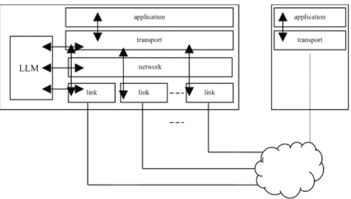
Figure 1: Mobile host with 3 interfaces
Although some routing protocols like OSPF [13] allow the use of multiple paths for a single route, the most common behavior for network connections is to follow a single path. Unless path multiplicity is done at the link layer, and link layer mechanisms are used to resequence packets, the use of multiple paths tends to generate out-of-order deliv-ery, which has harmful effects to transport layer connec-tions. IP has no resequencing mechanism, and does not promise in-order delivery of packets. IP’s route matching algorithm for unicast under CIDR [14] chooses the most specific match for each packet destination, and uses the first matching entry to disambiguate multiple matching rules. IP also has a multicast option, which delivers the same packet to multiple destinations. IP has no built-in
mechanism for multiplexing1 a single flow to multiple
destinations, addressed by a single or different IP num-bers. In fact, the disambiguating mechanism mentioned above will not allow multiple paths to a single IP address even if this IP address appears in multiple entries in the routers routing table. IPv6 does not add any mechanism to allow multiplexing, although it has a new mechanism to
help mobility, the anycast address type, that allows a
packet to be delivered to one of multiple IP addresses.
Our goal is to allow a multihomed mobile host to use mul-tiple network layers concurrently for the same flow using the current IP infrastructure. Figure 1 shows a host that can potentially use three interfaces, but current practices will not allow a single flow to be routed through all inter-faces simultaneously. Our solution is to create a transport layer mechanism to overcome the routing problems pre-sented to multihomed mobile hosts due to multiple simul-taneous network attachment points. A multiplexing trans-port protocol can use multiple link layers concurrently to deliver a single flow, and can deal with the problems posed by out-of-order delivery and the changes in avail-able bandwidth on the path of packets transmitted through
each network layer. The next section describes our
chan-nel abstraction, a mechanism for creating a single trans-port layer connection using multiple network layers simul-taneously. The term connection is used loosely, as the transport layer can be an UDP-like connectionless proto-col.
3 The Channel Abstraction
The goal of our research is to allow a mobile host to use multiple link layers simultaneously for a single data flow.
For this we define a channel, which is an end-to-end,
transport layer connection that encompasses all available layer links and multiplexes the data of a single flow into
these links. The sending application sees a single channel,
one transport layer interface that remains stable. The trans-port layer protocol receives the data from the application
and sends it through sub-channels, network layer sockets
mapped to different link layers. At the other end, the
trans-port layer gathers the data from the sub-channels and
de-livers it to the peer application. To create a channel, we
need information about what link layers are available. The
transport layer has to be link layer aware, although it will
not communicate directly to the link layer, relying instead on the abstractions offered by the network layer.
The number of sub-channels will depend on the
availabil-ity of network access points for different technologies in the range of the mobile system. The addition and deletion of sub-channels, as the mobile enters or leaves the cover-age area of one access point, is transparent to the applica-tion. The only side effect noticeable by applications of
sub-channel addition and deletion is the variation in
able bandwidth. We do not expect that all network inter-faces in the mobile host will be used constantly. The user may impose restrictions on usage depending on cost, the operating system may limit usage depending on the levels of battery power, and large mismatches of link layer char-acteristics may prevent the use of all available interfaces simultaneously. On the other hand, we will show in Sec-tion 4 that it is hard to know path characteristics without actually using it, and raw bandwidth is not a good indica-tor of available bandwidth.
The main benefit of multiplexing data into multiple inter-faces is the added bandwidth on the last hop, the common bottleneck link for mobile hosts. There are many other benefits, such as providing a natural way to deal with host mobility, smoother handoffs and greater link reliability. Location issues are important if the connection is destined to a mobile host, as opposed to connections initiated at the mobile host. This can be solved by mechanisms in current use today, so location issues are orthogonal to this paper. An application does not have to be aware of host mobility. On the other hand, more sophisticated applications may benefit from extra information, so an interface to query the
main channel characteristics is available, together with an
asynchronous notification system to report changes in these characteristics.
3.1
Architecture
The main components of our channel architecture are
de-picted in Figure 2. There are five entities: the application, the transport layer, the network layer, the link layer and the link layer manager; and three interfaces: the
applica-tion/transport layer interface, the transport layer/network
layer interface, and the link layer notification interface.
This work is centered on the transport layer. The channel
is the end-to-end connection that can be accessed by the interface between the application and the transport layer. The transport layer receives data from the application and
multiplexes this data into the available sub-channels. Each
sub-channel is mapped to a link layer interface through the network layer. This is shown on the figure as the arrows that go from the transport layer to the link layer. The
transport layer has to be link-layer aware. This can be
achieved through an entity that does link layer manage-ment (LLM in Figure 2). The LLM is responsible for link layer discovery, IP address management, and for
inform-ing the transport protocol of the presence of new
sub-channels,. The LLM also informs the transport layer if a current network attachment is lost, which implies in the
loss of the attached sub-channel.
3.2
The Application/Transport Layer Interface
For current applications, the most important interface is
the one that gives access to the virtual channel offered by
the transport layer. The interface to the channel mimics an
interface to a non-multiplexed transport protocol. Thus, it can be used as such by an application. The application gains mobility and robustness, and need not be changed. A normal socket interface can be used. Signals are used for asynchronous notifications from the transport protocol to the application. A signal handler is installed by the appli-cation if it desires to be notified of events, generated for example if the transport protocol has to violate the pa-rameters set by the application. Some of these papa-rameters are defined below.
Figure 2: The Channel Abstraction
Channel Parameters
For a typical application in current use today, using the
above-defined channel is an easy way to use bandwidth
aggregation and mobility. The application opens a socket using one of the transport protocols that implements our
channel abstraction and sends data normally. For applica-tions that have special quality of service (QoS) needs and for controlling the amount of bandwidth each application
gets, three parameters are defined: max rate, latency, min
rate.
The max rate sets a hard limit on the amount of data
sent/received. The application uses the max rate as a cap
on the maximum amount of data it can send. For the
trans-port layer, the max rate is used for flow control, and
de-fines the maximum amount of data an application can
re-ceive in a unit time. A similar max rate is used at the
The latency is a measure of the time between when a packet is sent and received, or half a round trip time if the sub-channel is symmetric. It is mostly transparent for ap-plications, as after the steady state is achieved in a connec-tion, the interarrival times are more important than the transit times. However, it is an important measure for the transport layer to decide if a new channel is added or not to protocol processing. Great mismatches in latency can increase the size of the buffers at the sender or receiver. If packets are sent in sequence, they will arrive out-of-order, which requires buffering at the receiver to reorder them. If ordering is done by changing the order packets are sent, packets have to be buffered at the sender. The size of the buffers needed for ordering is directly proportional to the latency mismatch of the sub-channels.
The min rate is a QoS parameter. An application can set the min rate to signal that the interarrival times of the packets in its stream are bound to that interval, and if they arrive later than that they will be useless. The transport protocol can use this knowledge to increase the number of packets that arrive in time if the aggregated bandwidth of the channel is smaller than the min rate by dropping pack-ets at the sender.
By offering these parameters, the channel turns into a
cross-layer communication middleware that frees the ap-plications from having to implement their own timing al-gorithms. At the same time, it adds bandwidth aggrega-tion, by the use of multiple channels, and mobility capaci-ties, by the ability of adding and deleting channels.
3.3
The Sub-Channel Interface
The interface between the transport layer and network layer is also simple, with a small twist. Because we as-sume that all network access points will be connected to the Internet, any interface can be used to deliver any packet. On the other hand, we want to control which link layer is being used to transmit each packet. To that end,
we have to be link layer aware. Each packet that is sent is
tagged with the appropriate interface, and will be sent through that interface regardless of the contents of the mo-bile’s routing table. This bypasses the IP routing layer. A way to achieve this has been developed for Linux systems, with the socket call SO_BIND_TO_INTERFACE [2].
3.4
Link Layer Access
One aspect that has been overlooked in mobile research is link layer access. Most mobility solutions assume that the link layer configuration will be automatic and base trigger mechanisms in the presence of network layer connectivity. We believe that there is the need for a framework for link
layer access, to standardize the operating system interface, creating an unified API [15] to report the presence of ac-cess point in the vicinity of the mobile, and to do AAA (Authentication, Authorization and Accounting). A multi-plexing transport protocol has to be aware of new link lay-ers that become available, and of link laylay-ers that can no longer be used, to add and remove these interfaces from protocol processing. To this end, a link-layer aware trans-port protocol needs the following suptrans-port:
Link layer management: a management entity can use direct information (by probing or listening to the link layer for the presence of access points) or indirect information (by using an existing connection to query the infrastruc-ture for the existence of additional access points) to find
new access points. This is called link layer discovery.
Management also encompasses measuring signal strength and possibly location hints to rule that a link layer is no
longer usable. This is called link layer disconnection.
Network layer management: before using a link layer, the mobile has to acquire an IP address for that interface. The most common protocol for acquiring a network ad-dress in broadcast media is DHCP (Dynamic Host Con-figuration Protocol) [16]. For point-to-point links, such as infrared, acquiring a network address also entails creating a point-to-point link. In this case, the link will only be cre-ated on demand, as creating the link precludes other mo-biles from using the same access point.
Transport layer notification: the transport layer has to be notified of new access points (in the form of a new IP ad-dress it can use) and of the loss of an active access point (an IP that can no longer be used). The transport protocols can also notify a management entity about the available bandwidth of each link. Because this bandwidth is closely tied with the available bandwidth of the last hop, by con-trolling the maximum bandwidth each protocol instance can use the management entity to enforce usage policies for cooperating protocols.
4
Protocol Mechanisms
Once the problem of sending data to a specific
sub-chan-nel is solved, we have to create a mechanism to multiplex
data into these sub-channels. We want an end-to-end
In this section, we will present the mechanisms used for bandwidth estimation, traffic shaping and discerning transmission losses from congestion losses. The common thread of these techniques is the rate-based transmission mechanism. We end this section by showing how the mul-tiplexing mechanism helps host mobility.
4.1
Bandwidth Estimation
A simple mechanism to measure the available bandwidth on a link is the packet-pair method [17]. It entails sending two packets back-to-back on a link, and measuring the in-terarrival time of those packets at the receiver. If the pack-ets are sent on a point-to-point link with no other traffic, the interarrival time measures the raw bandwidth of the link for that size of packets. It is the absolute minimum period at which packets of that size can be sent. Sending packets at a smaller spacing will only queue packets at the outbound interface, with no increase in throughput. If the packets are sent on a multiple hop path mixed with other traffic, routers on the way may insert other packets be-tween the two packets that were sent back-to-back, mak-ing them arrive farther apart. The number of packets in-serted is directly proportional to the load on the outbound port each router uses to send the packets, and does not de-pend on packet size if no fragmentation occurs, as time in the routers is normally bound by protocol processing and not packet size. If packet size is equal to the path MTU, the interarrival time measured at the receiver is a snapshot of the bandwidth of the path. The interarrival time is the minimum period at which packets can be sent that will not create a queue in any of the routers on the path. If the load of all routers in the path is a constant, then the inverse of the interarrival time defines the optimal rate to send pack-ets through this link. The load not being a constant, the measurement will have to be repeated from time to time to adjust the rate to the current conditions.
4.2
Traffic Shaping
To achieve a certain rate of packets per second, many strategies may be used. We can send all packets back to back in the beginning or end of a period, and let the link be idle for the remainder of the period. Packets may be sent in regular or irregular bursts all through the period, or packets may be sent at regular intervals during the whole period. Traffic shaping occurs at the bottleneck router if a single flow achieves the maximum path bandwidth. No matter how packets are sent, they will end up evenly spaced at the receiver, and the spacing will be the one given by the packet pair method. The queue size on the bottleneck router, on the other hand, will vary greatly ac-cording to the transmission strategy. A single large burst will produce the largest queue, while evenly spaced
pack-ets will produce very small queues, if any. Router queues are rather dangerous, as router buffer space is a precious commodity. If buffer space is exceeded, packets are dropped. This condition is also known as congestion, and obviously degrades performance and wastes bandwidth, for dropped packets have to be resent. Transport protocols try to stay below the maximum link bandwidth, and re-spond to lost packets by lowering their transmission rates, to prevent congestion. This is a good strategy, but may also have bad side effects if not all losses are caused by congestion, as will be seen below.
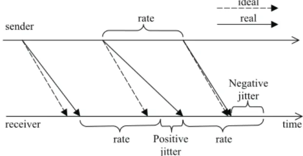
To minimize the queue size at the bottleneck router, pack-ets can be sent at regular intervals according to the maxi-mum path bandwidth. This has an interesting side effect of allowing the measurement of decreasing link bandwidth without using the packet pair method. The reasoning fol-lows: if packets are sent at regular intervals at below path bandwidth, there will be no traffic shaping at the bottle-neck router, and changes in the interarrival times will be caused by traffic fluctuations. The jitter caused by traffic fluctuations tend to cancel out, for if a packet is late, and produces positive jitter, the next packet will be early in re-lation to it, and produce negative jitter. Figure 3 shows the effect of traffic fluctuation on the arrival times seen at the receiver, with the resulting positive and negative jitters. If a cumulative sum of jitters is maintained, it hovers around zero, because the positive and negative jitters tend to can-cel out. If the cumulative sum does not cancan-cel out that means that the packet transmission rate is above the maxi-mum the channel can bear, and traffic shaping is happen-ing at a router on the path, with the resulthappen-ing queues. Therefore, by sending packets at regular intervals, and tracking the interarrival times at the receiver, it is possible to measure changes in path bandwidth without using the packet pair method.
Figure 3: positive and negative jitter
4.3
Discerning Transmission Losses from
Congestion Losses
will generally use wireless links, which present a greater error rate on transmission than wired links. It is important to discern if errors were caused by congestion, at which time congestion control measures have to take effect, or were caused by transmission errors, and can be ignored. If all errors are considered congestion related, it will de-crease the throughput of a transport protocol. Using regu-larly spaced packets, the telltale signs of congestion are an increase in the interarrival time seen by the receiver, caused by growing queues at one of the intervening rout-ers, as was seen above. If a loss is accompanied by a growing trend in the interarrival times, the loss is probably a congestion loss. If not, it is probably a transmission loss, and no further action has to be taken.
4.4
Rate-Based Transmission Mechanism
The mechanism described above is well known in the lit-erature: a rate-based transmission mechanism. The same rate-based transmission mechanism can be used for load balancing, bandwidth tracking and congestion control. A
channel is formed of multiple network layer connections, each with a different IP address, and multiplexing is achieved by load-balancing data into each of these connec-tions according to the available bandwidth measured by running independent rate-based transmission mechanisms in each connection.
4.5
Mobility
By uncoupling the transport layer from the network layer
[6], the channel creates an easy path for host mobility.
While Mobile IP has to keep track of the original IP ad-dress of the mobile host, because transport layer tions use this number as part of their identifier, a
connec-tion using the channel abstraction does not need to keep
track of IP addresses. In fact, other than for location, the original IP address of the mobile host is not used at all. All IP addresses are transient, and can change from base sta-tion to base stasta-tion. This does not preclude the use of link layer mobility, though. To use the current infrastructure, a cellular modem connection is seen as one sub-channel, though as the user moves it may use different base-sta-tions.
The algorithm for congestion control for the channel also
takes the wireless characteristics of the sub-channels nor-mally used by mobile host into account. While TCP suf-fers from a hit in performance due to transmission errors
in wireless links [12, 18], the sub-channelscan discern the
type of error that occurred, and react accordingly. The same performance hit is taken by TCP during a Mobile IP handoff, because of lost packets and changes in path char-acteristics. Because moves from one base station to
an-other can be continuous in the channel, as it is not
neces-sary to relinquish the first connection to create another one, handoffs are smoother, and transport protocol is not affected by the change itself from one attachment point to another. Of course, variations in the bandwidth available in each base-station will still influence the protocol’s per-formance.
5
The Multiplexing Transport Protocol
Suite
The two transport protocols most commonly used in the Internet are TCP, which offers a reliable stream, and UDP, which offers a connectionless datagram service. We do not offer a connectionless protocol, because the mechanisms of a rate-based protocol need a longer-lived connection to work, as they use feedback from the receiver. The interar-rival time of packets is measured at the receiver and is cru-cial for estimating the available bandwidth and for dis-criminating congestion and transmission losses. On the other hand, a multiplexing unreliable protocol that offers congestion control can be used as a basis of other proto-cols. The regularity of a rate-based protocol lends itself naturally to multimedia applications. Sound and video need bounds on arrival time so that the playback can be done smoothly. A multimedia protocol is the natural off-shoot. Most multimedia applications need timely data. Data received after the playback time is useless. More-over, for a system with bandwidth constraints, late data is adverse to the quality of playback, as it robs bandwidth from the flow. There are many strategies to deal with losses, from forgiving applications to forward error cor-rection (FEC) schemes. Retransmissions are rarely used, because they take the place of new data, and the time to send a request and receive the retransmission may exceed the timing constraints.
When multiple channels are available, and the aggregated bandwidth is greater than the bandwidth necessary to transmit the multimedia stream, retransmissions can be done successfully without harming the quality of play-back. The simultaneous use of multiple link layers gener-ates extra bandwidth. The best-case scenario is the cou-pling of a low bandwidth, low delay interface with a high bandwidth, high delay interface. The high bandwidth in-terface allows for a good quality stream, while the low de-lay interface makes retransmissions possible by creating a good feedback channel to request (and transmit) lost frames.
characteristics of its stream. Adapting applications can change the quality of the stream on the fly to deal with bandwidth variations [19], but for non-adapting applica-tions, the best policy is to drop packets at the sender. Sending packets that will arrive late will cause further problems by making other packets late, which can have a snowball effect.
In contrast to a multimedia protocol, a reliable protocol has to deliver intact every packet that the application sent. In this case, time is not the most important factor. Lost or damaged frames will have to be retransmitted until they are successfully received. If the application expects the data to be received in the same order it was sent, the proto-col will have to buffer packets received after a loss until the lost packet retransmission is received. Using the chan-nel abstraction to multiplex the data increases the occur-rence of out-of-order deliver, increasing the burden in the receiving end.
We present in the next two subsections the protocols we
implemented that instantiate the channel abstraction. The
first is a protocol for multimedia traffic, and the second is a reliable protocol. Both share the underlying charac-teristics, although they are designed for very different tasks. We present a short description of the protocol, with experimental results that highlight their characteristics.
5.1
MMTP
The first protocol in the suite is a specialization of the un-reliable protocol for multimedia traffic. The Multimedia Multiplexing Transport Protocol (MMTP) [7] is a rate based multiplexing protocol designed to carry packets with hard deadlines. MMTP supports the transmission of time sensitive rate-based data streams that may be gener-ated live or from stored data. Given the characteristics of the data streams in terms of frame rate and bandwidth
re-quirements, MMTP creates a channel that multiplexes the
data into any available communication sub-channel. As
the available sub-channels change, MMTP adapts, adding
or removing sub-channels as necessary. MMTP provides
a best effort service. If the aggregation of available
sub-channels does not provide enough bandwidth for the
ap-plication stream, MMTP will drop packets that it estimates cannot arrive on time and inform the application of the lack of necessary resources.
The main task of MMTP is the decision as to which sub-channel to use for transmitting the current packet. This decision is based on estimations of the bandwidth and de-lay characteristics of each sub-channel. After startup, two control mechanisms are used to adapt the sending rate to the sub-channel bandwidth: rate decrease messages and
channel probe. Rate decrease messages are sent to prevent congestion when the receiver notices that the channel bandwidth is below the sender’s rate. Probing is used to track increases in bandwidth
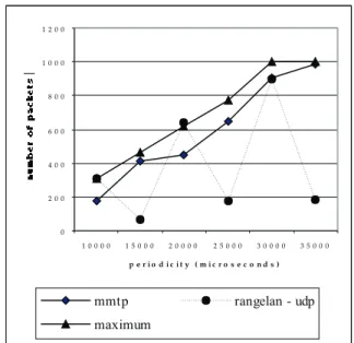
The test setup for MMTP has a source process that creates frames at the given periodicity and sends them to the proxy. The proxy sends these frames to the receiver on the mobile. We run experiments comparing the performance of a simple UDP algorithm that sends packets according to the source rate to the performance of MMTP. MMTP drops packets that it assumes will not arrive at the receiver before their deadline, while the UDP algorithm will try to send all packets, even if it exceeds the link bandwidth.
Figure 4 shows the number of packets that were received within their deadline for different source rates (given by the period in microseconds).
Figure 4: number of frames that arrive in time versus source period
These results show that measuring bandwidth and choos-ing what frames should be sent save bandwidth at the wireless interface. Using these techniques also increases the number of frames that arrive before their deadline, even though fewer frames are being sent. MMTP does not achieve the maximum theoretical throughput, which can be explained by the conservative approach to bandwidth tracking. MMTP tries to stay below the maximum avail-able bandwidth to prevent link congestion, and this pre-vents MMTP from attaining the results that UDP can get on some cases by flooding the link.
Figure 5 shows the number of frames that arrived after their deadline had expired. Because UDP floods the wire-less interface, many packets are dropped due to buffer
0 2 0 0 4 0 0 6 0 0 8 0 0 1 0 0 0 1 2 0 0
1 0 0 0 0 1 5 0 0 0 2 0 0 0 0 2 5 0 0 0 3 0 0 0 0 3 5 0 0 0
overflow at the base station. The side effect is that at cer-tain source rates the loss pattern contributes to a good re-sult. At other rates, although more packets are being deliv-ered, they are past their deadline, and so useless to the ap-plication.
Figure 5: number of frames that arrived late versus source period
These results show that measuring bandwidth and choos-ing what frames should be sent save bandwidth at the wireless interface. Using these techniques also increases the number of frames that arrive before their deadline, even though fewer frames are being sent. MMTP does not achieve the maximum theoretical throughput, which can be explained by the conservative approach to bandwidth tracking. MMTP tries to stay below the maximum avail-able bandwidth to prevent link congestion, and this pre-vents MMTP from attaining the results that UDP can get on some cases by flooding the link.
5.2
RMTP
One of the target applications for mobile communications is access to the world wide web. This requires a reliable protocol in the molds of TCP. We built the Reliable Multi-plexing Transport Protocol (RMTP) with those require-ments in mind. RMTP is a protocol designed for the reli-able transmission of bulk data to mobile systems that have access to multiple link-layer technologies. RMTP is de-signed as a multiple channel, rate-based, fixed window size protocol that uses selective acknowledgements for re-liability, and bandwidth estimation for flow and conges-tion control.
Multiple communication sub-channels will coexist if the
mobile has multiple network interfaces, these interfaces are active simultaneously, and have acquired one
exclu-sive IP address. To multiplex data into those multiple
sub-channels it is necessary to know the sub-channel charac-teristics, particularly the available bandwidth, for load bal-ancing. We use the packet pair method for measuring bandwidth, and the rate-based transmission mechanism used in RMTP keeps the regularity of the traffic generated by the protocol. The regularity in which packets are trans-mitted in RMTP also allows the interarrival time to be used as an aid to differentiate congestion losses from me-dium losses. Because RMTP is a protocol for mobile sys-tems, it will be used mostly in wireless environments, where losses caused by transmission errors are orders of magnitude greater than in wired environments. One of the problems of using TCP in mobile systems is the well know mechanism of slowing down transmission in the presence of losses, which are used an indicator that the protocol exceeded the available bandwidth (i.e., it is creat-ing congestion on a link). TCP has no way of discerncreat-ing the cause of the loss because it sends packets in bursts. RMTP analyses the interarrival times to discern if a loss was most likely caused by the wireless medium or if the link is congested. Because packets are spaced regularly, channel jitter is canceled out, and an increase in the inter-arrival time signals channel congestion.
RMTP measures the minimum interarrival time of each channel and multiplexes packets on the channels accord-ing to the resultaccord-ing periods. Multiplexaccord-ing gives a very good abstraction for dealing with mobility: if we assume that all channels are available all the time, but their period is infinite, adding a channel is just changing the period from infinite to a finite value, and deleting a channel is just setting the period to infinity. On the other hand multi-plexing requires special attention on the reliability algo-rithms. Out of order delivery is a very common occurrence due to the different transmission delay on each channel, so we decided to use selective acknowledgements to allow each channel to do its own gap detection, although each packet that is lost is put on the common queue to be re-transmitted by the first available interface.
Because traffic conditions on communication channels are in general not static, the first bandwidth measurement done at startup will not be valid for long. RMTP changes
the sending periods on individual sub-channels according
to the available bandwidth of that sub-channel, increasing
the period in case of congestion, and decreasing the period if more bandwidth becomes available. Congestion is sig-naled by increases in the interarrival time and by losses. RMTP will react mildly to increasing interarrival times, by increasing the period on the channel with increasing
inter-0 2 5 0
7 3
1 0 0
1 0 5 8 2
6 7 5 3
0 8 1 8
0 1 0 0 2 0 0 3 0 0 4 0 0 5 0 0 6 0 0 7 0 0 8 0 0 9 0 0
1 0 0 0 0 1 5 0 0 0 2 0 0 0 0 2 5 0 0 0 3 0 0 0 0 3 5 0 0 0
arrival times an amount corresponding to this increase. If a loss occurs in this condition, the sending period of the channel is doubled. This technique avoids congestion, be-cause no losses are necessary to indicate channel conges-tion [20].To track increasing bandwidth, RMTP will probe the channels regularly. The probing interval will vary to reflect the recent history, growing shorter if the channel bandwidth is increasing, and increasing if the channel is experiencing congestion.
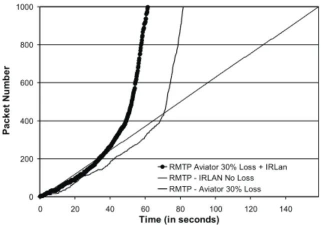
We tested RMTP by comparing its performance with TCP in lossy and lossless wireless links. The test program sends 1000 packets of 1400 bytes each using TCP and RMTP, and measures the arrival time of those packets. The arrival times are plotted in the graphs. Packet losses are seen as horizontal lines, which indicate the time it takes the protocol to recover from the loss. For these ex-periments, we used a wireless Ethernet, a 2.4GHz WebGear Aviator, which gives 2Mbps of throughput, and an infrared interface using IrLAN (IRDA LAN emula-tion), with a 115Kbps throughput. The difference of throughput should make the wireless Ethernet much bet-ter, but it is running with 30% loss given by our test setup. In a lossless environment, the wireless Ethernet finishes the test in less than 10 seconds. Figure 6 shows the per-formance of RMTP and TCP under these conditions. We can see that contrary to the expected, TCP presents better throughput using the infrared interface, which is lossless, due to the long wait the losses cause on the Ethernet. RMTP does not suffer the problems of slow-start on pres-ence of losses; and by using both interfaces at the same time has a much better result.
Figure 6: Comparison of TCP and RMTP over IrLAN and Aviator
The next graph, Figure 7, shows the comparison of RMTP’s performance using each interface independently and using both at the same time. The current views sup-port that using the infrared interface would not present any gains, because the throughput mismatch of the two
inter-faces is too large. Even though RMTP is more immune than TCP to packet loss, adding the infrared interface boosts the performance by 25%, yielding a much better re-sult than would be expected.
Figure 7: Comparison of single links and multiplexed channel on RMTP
6
Conclusions and Future Research
Our channel abstraction creates a good framework for
building transport protocols for mobile systems that share the characteristics of bandwidth aggregation, congestion avoidance and good performance on wireless links. The mechanisms used to this end are inverse multiplexing and traffic shaping (rate-based transmission). The
experimen-tal results show that protocols created using the channel
abstraction can be used for very different purposes with good results.
We are currently working on the larger framework that en-compasses the Link Layer Manager and the location serv-ice to test the mobility characteristics of the protocols. We are also interested in power consumption measurements. Our intuition is that it may be possible to offset the higher power usage, caused by the concurrent use of multiple in-terfaces, with power savings by completing communica-tion tasks faster. This is backed up by the current experi-ments with the good results we had in the presence of transmission errors.
Acknowledgements
References
[1] M. Stemm and R. H. Katz, Vertical Handoffs in Wireless Overlay Networks. ACM Mobile Networking (MONET), Special Issue on Mobile Networking in the Internet, 1998.
[2] X. Zhao, C. Castelluccia, and M. Baker, Flexible Net-work Support for Mobility. in Fourth ACM International Conference on Mobile Computing and Networking (MOBICOM’98), 1998.
[3] F. M. Chiussi, D. A. Khotimsky, and S. Krishnan, Gen-eralized inverse multiplexing of switched ATM connec-tions. in Proceedings of the IEEE Conference on Global Communications (GlobeCom ’98), 1998.
[4] A. C. Snoeren, Inverse Multiplexing for Wide-Area Wireless Networks. in Proceedings of the IEEE Confer-ence on Global Communications (GlobeCom ’99), Global Internet Symposium, 1999.
[5] K. Sklower, B. Lloyd, G. McGregor, D. Carr, and T. Co-radetti, The PPP Multilink Protocol, RFC1990., 1996.
[6] A. Snoeren and H. Balakrishnan, An End-to-End Ap-proach to Host Mobility. in ACM Mobicom ’99, 2000.
[7] L. Magalhaes and R. Kravets, MMTP: Multimedia Mul-tiplexing Transport Protocol. in The First Workshop on Data Communications in Latin America and the Carib-bean (SIGCOMM-LA 2001), 2001.
[8] Airlines to expand wireless Web access at airports. in As-sociated Press, 2000.
[9] Starbucks and Microsoft Connects Internet With Coffee. in Business Wire, 2001.
[10] C. Perkins, IP Mobility Support. IETF RFC 2002.
[11] D. B. Johnson and C. Perkins, Internet-Draft, draft-ietf-mobileip-ipv6-13. IEFT November 2000.
[12] R. Caceres and L. Iftode, Improving the Performance of Reliable Transport Protocols in Mobile Computing En-vironments. IEEE Journal on Selected Areas in Commu-nications, vol. 13, 1995.
[13] J. Moy, RFC2328: OSPF Version 2. IETF 1998.
[14] V. Fuller, T. Li, J. Yu, and K. Varadhan, Classless Inter-Domain Routing (CIDR): an Address Assignment and Aggregation Strategy. Internet Engineering Task Force, Request for Comments (Experimental) RFC 1519, Sep-tember 1993 1993.
[15] L. Magalhaes, A Framework for Link Layer Manage-ment in Mobile Systems. in Illinois Computer Affiliates Program 2000, 2000.
[16] R. Droms, RFC 2131: Dynamic Host Configuration Pro-tocol. IETF 1997.
[17] S. Keshav, A Control-Theoretic Approach to Flow Con-trol. in Proceedings of the SIGCOMM ’92 Symposium, 1992.
[18] H. Balakrishnan, V. Padmanabhan, S. Seshan, and R. Katz, A Comparison of Mechanisms for Improving TCP Performance over Wireless Links. in Proceedings of the SIGCOMM ’96 Symposium, 1996.
[19] S. Servetto and K. Nahrstedt, Broadcast Quality Video over IP. IEEE Journal on Selected Areas in Communi-cations, Special issue on QoS in the Internet, 1999.