AN OPTICAL FLOW-BASED SENSING SYSTEM FOR REACTIVE MOBILE
ROBOT NAVIGATION
Eliete Maria de Oliveira Caldeira
∗ [email protected]Hans Jörg Andreas Schneebeli
∗ [email protected]Mário Sarcinelli-Filho
∗ [email protected]∗Departamento de Engenharia Elétrica - Universidade Federal do Espírito Santo
Av. Fernando Ferrari, 514, 29075-910 Vitória/ES Brazil Voice: +55 27 4009 2684 Fax: +55 27 4009 2737
ABSTRACT
This work discusses the use of optical flow to generate the sensorial information a mobile robot needs to react to the presence of obstacles when navigating in a non-structured environment. A sensing system based on optical flow and time-to-collision calculation is here proposed and experi-mented, which accomplishes two important paradigms. The first one is that all computations are performed onboard the robot, in spite of the limited computational capability avail-able. The second one is that the algorithms for optical flow and time-to-collision calculations are fast enough to give the mobile robot the capability of reacting to any environmen-tal change in real-time. Results of real experiments in which the sensing system here proposed is used as the only source of sensorial data to guide a mobile robot to avoid obstacles while wandering around are presented, and the analysis of such results allows validating the proposed sensing system.
KEYWORDS: Optical flow; Mobile robots; Autonomous ve-hicles; Obstacle avoidance; Mobile robot navigation; Com-puter vision.
Artigo submetido em 10/01/2006 1a. Revisão em 19/01/2007 2a. Revisão em 19/04/2007
Aceito sob recomendação do Editor Associado Prof. José Reinaldo Silva
1
INTRODUCTION
Many applications of mobile robots demand the use of a CCD camera fixed onboard the mobile platform, like surveil-lance, remote inspection, etc. Thus, most mobile platforms include such sensor as part of its hardware resources.
In addition, vision is very likely to be the richest human sens-ing subsystem, for the wide gamma of information it can pro-vide (Farah, 2000; Ramel, 2000). Then, to make profit of the vision system available onboard the mobile robot is quite rea-sonable. However, for the sake of cost reduction, the vision system frequently available onboard the robot is a monocular one, thus imposing severe limitations on how to use vision to get useful information about the surrounding environment. Information about the amount of objects in the scene, for ex-ample, could be generated by simply segmenting an acquired image (Tekalp, 1995; Adams and Bischof, 1994; Bleau and Leon, 2000), but the relative depth of such objects would not be determined, thus making impossible to the robot to imple-ment the necessary maneuvers to avoid them.
Langlois and Latombe, 1992), which can be measured using sonar or laser range finder.
Regarding monocular vision, a technique exists that is able to provide information about the distance from a camera fixed onboard the robot to an object, which is based on the optical flow vector field (Horn and Schunck, 1981). The optical flow field is obtained by processing two or more sequential views of the same scene. Such technique has been explored in many applications, like plant growth monitoring (Barron and Lip-tay, 1997), video compression (Wallach, Kunapalli and Co-hen, 1994), automatic car driving (Giachetti, Campani and Torre, 1998; Batavia, Pomerlau and Thorpe, 1998), and mo-bile robot navigation (Ancona and Pogio, 1995; Carelli et. al., 2002; Dev, Kröse and Groen, 1997a; Baratoff, Toepfer and Neumann, 2000; Camus et. al., 1999; Coombs et. al., 1998; Santos-Victor et. al., 1995; Stöfler, Burkert and Fär-ber, 2000).
This paper addresses an application in mobile robot naviga-tion that uses the optical flow technique to get all the informa-tion the robot needs to safely navigate. In some applicainforma-tions regarding the use of optical flow in mobile robot navigation, a special camera arrangement (Coombs et. al., 1998; Santos-Victor et. al., 1995), a single special camera (Camus et. al., 1999; Coombs et. al., 1998) or specialized hardware pieces (Ancona and Pogio, 1995; Stöfler, Burkert and Färber, 2000; Carelli et. al., 2002; Dev, Kröse and Groen, 1997a; Coombs et. al., 1998) has been adopted in order to get more accu-rate information or to acceleaccu-rate the optical flow calculation. Such resources are not available here: the only sensor used is a perspective camera with small aperture angle (48.8 degrees in the horizontal direction) fixed on the robot. Therefore, the solution adopted is to pay special attention to the calculation of the optical flow vectors.
In other applications related to mobile platforms navigation, for the restrictions on the computational capability, most re-sults so far published consider some simplification: process-ing just small parts of the acquired images (Carelli et. al., 2002; Dev, Kröse and Groen, 1997a; Giachetti, Campani and Torre, 1998; Batavia, Pomerlau and Thorpe, 1998), acquiring and processing smaller images (Lorigo et. al., 1997), or even performing the calculations off-board the robot (Carelli et. al., 2002; Dev, Kröse and Groen, 1997a), are strategies com-monly adopted. In the last case, a more efficient computer off-board the robot receives the images it acquires, performs the calculations and sends a control signal back to it. How-ever, in such a case the robot autonomy is restricted, once the robot is constrained to keep close the off-board computer, for not loosing communication. Other strategy that has been re-cently adopted is the pre-processing of the images acquired to generate a more compact set of input data, which would cause the processing time to be reduced. However, the
re-sults so far obtained have not allowed increasing the image acquisition rate (Baratoff, Toepfer and Neumann, 2000). No simplifications like those above mentioned are adopted here: the images used are 240x320 pixels grey level bitmaps, and all the calculations are performed onboard the mobile plat-form.
The optical flow-based sensing system here proposed gener-ates a one-dimensional map of depths corresponding to the horizon in front of the robot, covering its entire field of vi-sion. The behavior wandering (Brooks, 1986), meaning that the robot moves itself around just avoiding obstacles, is im-plemented, in order to demonstrate the capability of the opti-cal flow-based sensing system proposed to deal with obstacle detection and avoidance. Moreover, no other sensing appa-ratus than the CCD camera is used, once the optical flow technique is able to provide the necessary sensorial informa-tion. Finally, the entire system is implemented in a computer onboard the mobile platform, thus guaranteeing its full au-tonomy.
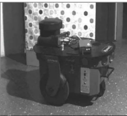
The tests with the system here developed were performed with the ActivMedia Pioneer 2-DX mobile robot (see Fig-ure 1), whose onboard computer is based on the Intel Pen-tium MMX 233 MHz processor, and includes 128 Mbytes of RAM memory. The CCD camera onboard the robot is a SONY D30/D31 analog one, attached to a PC Imagena-tion frame grabber. The robot also embeds Saphira, an API that allows the programmer to get sensorial information and to actuate on the robot motors, through passing setup val-ues for the heading angle and the linear speed. Actually, Saphira delivers to the robot embedded microcontroller (a Siemens 20 MHz 88C166 one) the low-level actuation sig-nals, in accordance with the high level commands it receives. It also allows the programmer to get information from the robot odometry, which is here used to recover the trajectory the robot followed.
For describing the system implemented, the paper is
inafter structured in five sections. Section 2 discusses the algorithm adopted to perform the optical flow calculation, which is one of the main responsible for guaranteeing the real-time characteristic of the whole system. In the sequence, Section 3 discusses an algorithm adopted to perform the mo-tion segmentamo-tion (Tekalp, 1995), based on the optical flow vectors calculated, which produces the map of depths used by the robot to avoid obstacles, here referred to as the vector of times to collision or times to contact. Next, Section 4 deals with a state-machine implemented to allow the robot to avoid obstacles in some different contexts, which is based on the vector of times to collision generated in Section 3. Finally, Section 5 shows some experimental results, while Section 6 highlights the main conclusions.
2
OPTICAL FLOW CALCULATION
The main paradigm to be considered here is to implement an algorithm that calculates the optical flow vectors as fast as possible, in order to preserve the capability of the sys-tem of reacting to any environmental change in real time. As images should be acquired in an acquisition rate of thirty frames per second, the acquisition of several image frames would demand a lot of time, so that the first step of choos-ing a suitable algorithm was to impose that no more than two image frames should be acquired. Also, only gradient-based methods for optical flow calculation (Barron, Fleet and Beau-chemin, 1993) were considered. Another strong limitation was not to consider iterative algorithms, like the classical one due to Horn and Schunck (1981), for the large computation time demanded to get a good optical flow vectors estimate.
Then, starting from the analysis of the methods for optical flow calculation presented in (Barron, Fleet and Beauchemin, 1993), the least-squares algorithm proposed by Lucas and Kanade (1981) was selected as the candidate to estimate the optical flow vectors. In such an algorithm, the optical flow is considered constant in a region of N by N pixels. Thus, writing the optical flow constraint for each pixel in the region one gets the set of observations
Ixpu+Iypv+Itp= 0forp= 1, ..., N×N, (1)
from which the least squares estimate
(ˆu,vˆ) =ATA−1ATb (2)
of the optical flow vector is obtained, where
A=
Ix1, Ix2, ..., IxN×N
Iy1, Iy2, ..., IyN×N T
and
b=−It1, It2, ..., ItN×N T
.
Other algorithms available in the more recent literature were also tested, like those proposed in (Grossmann and Santos-Victor, 1997), (Nesi, Bimbo and Ben-Tzvi, 1995) and (Lai and Vemuri, 1998), mainly for the robust and high-quality estimate they generate.
Tests run with this group of algorithms are reported in (Sarcinelli-Filho et. al., 2002b), and the main result is that the more robust algorithms demand a computation time that is much higher than that demanded to get the least-squares estimate. Hence, as low computation time is a main paradigm in the application here considered, the least squares optical flow vectors estimate was selected as the most suitable one for onboard implementation. However, to reduce the num-ber of pixels of each one of the two image frames used when writing the observation equations, like it is done in (Gross-mann and Santos-Victor, 1997), showed to be very interest-ing. Following this strategy, our implementation adopts re-gions of 10x10 pixels (24x32 rere-gions in each image frame) and adopts 12 observations for processing the optical flow estimate associated to each region. The computation time as-sociated to such a modified least squares estimate is summa-rized in Table I. The main result of such an implementation is that real-time performance is assured to the sensing system here proposed.
However, experiments have shown that such an algorithm generates rougher estimates of the optical flow vectors, in comparison with the classical least-squares estimate. Actu-ally, in all the experiments run it generated an underestimated time to contact when the robot approached an obstacle. Nev-ertheless, the rougher estimate of the optical flow vectors, from which the time to contact emerges (Dev, Kröse and Groen, 1997a), does not represent any danger to the robot, in this case, once any evasive maneuver is started in advance.
3
OPTICAL FLOW-BASED IMAGE
SEG-MENTATION
With the objective of making easier to get information about the environment surrounding the robot, it was implemented an image segmentation step entirely based on the optical flow vectors previously calculated. The result of such segmenta-tion is to disclose the distinct objects present in the scene.
associ-ated to different moving objects in the 3D scene (Borshukov et. al., 1997; Tekalp, 1995). Therefore, the optical flow-based segmentation corresponds to group pixels whose opti-cal flow vectors are similar, thus corresponding to the same movement in the image frame considered. Then, considering that the optical flow field is a good representation of the field of movement, each group of pixels emerging from the seg-mentation is associated to a single 3D structure. An impor-tant aspect, in this sense, is that the accuracy of the result of the segmentation is straightforwardly connected to the accu-racy of the optical flow vectors previously calculated (Stöfler, Burkert and Färber, 2000). Actually, after calculating the op-tical flow vectors as described in Section 2, each vector rep-resents a region of 10x10 pixels in the image, such that a ma-trix of 24x32 different optical flow vectors is the data to be analyzed in order to detect objects in the image frame. There-fore, the image segmentation process is not time-consuming.
Table 1: Computation time associated to the least squares estimates of the optical flow.
Least squares estimate Normalized Computation time (%)
Classical one 100
Modified one 6.25
The methods available in the literature for optical flow-based image segmentation can be grouped in three main categories (Borshukov et. al., 1997). The first one corresponds to the use of affine clustering (Wang and Adelson, 1994), mean-ing to cluster pixels based on an affine optical flow model. For the second category, the segmentation is based on the dominant movement (Bergen, Burt and Hanna, 1992), where in the current iteration the region of dominant movement is identified and the movement it performs is estimated. The procedure is repeated in the next iteration, not including re-gions previously identified as rere-gions of dominant move-ment. The third category executes simultaneously the esti-mation and the segmentation of movements.
The method proposed by Wang and Adelson (1994) is an ex-ample of the use of affine clustering to segment movements. It supposes that the optical flow corresponding to an image frame can be described as a set of planar regions in the space of velocity, what means that the optical flow has an affine model in such regions. This way, the optical flow is estimated for the entire image, which is divided in rectangular regions, where the parameters of the affine model of the optical flow are estimated. As the models of regions corresponding to the same object in the real world, they are grouped in a small number of classes by using an adaptive k-means algorithm. An affine model is obtained for each group of regions with similar models, and then each optical flow vector is grouped
in one of the resulting classes.
The multistage affine segmentation method proposed by Bor-shukov et al. (1997) combines the method of segmentation based on the dominant movement of Bergen et al. (1992) and the clustering using the affine model adopted by Wang and Adelson (1994). The image is divided in rectangular blocks for which the parameters of the affine model of the optical flow are estimated. The parameters associated to the dominant movement are then determined, by combining the parameters of different regions. Then, the regions whose pa-rameters are well represented by this model are identified and grouped together. The procedure is repeated for the regions not included in any group, thus generating another vector characterizing a dominant movement, and so on.
The procedure proposed in this work uses a constant value as the model of the optical flow in each region of 10x10 pixels, in consonance with the algorithm adopted for optical flow calculation discussed in Section 2. It groups the contiguous regions characterized by optical flow vectors that are similar, according to the metric used in (Borshukov et. al., 1997) and (Wang and Adelson, 1994). Therefore, the optical flow vectors corresponding to the regionsrijandrklare similar if
(ukl−uij)2+ (vkl−vij)2< Tij, (3)
whereiandj indicate the row and the column of the region
rijunder consideration in the matrix of optical flow vectors, respectively,kandlindicate, respectively, the row and the column of one of the regions in the neighborhood ofrij,u andv are the components of the optical flow in the direc-tionsxandy, respectively, andTij is a threshold value for the regionrij. Such condition corresponds to say that two neighbor regions are similar if the squared magnitude of the difference between their optical flow vectors is below a cer-tain threshold.
Choosing the value of Tij is a very important issue, for a very low value could cause regions corresponding to a single 3D object not to be grouped during the segmentation proce-dure, as well as a very high value could cause the grouping of regions corresponding to different 3D objects. Besides, as the robot is most time approaching objects in the scene, the optical flow is expected to be a radial field of vectors. More-over, it is expected that the magnitude of the vectors diminish when the region under consideration is close to the focus of expansion of such field. Hence, it is not possible to use a sin-gle value forTij for all regions. After several experiments, it was decided to adopt 20% of the squared quadratic norm of the optical flow vector corresponding to the regionrij for the thresholdTij, which presented good results.
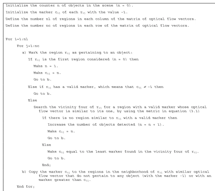
Initialize the counter n of objects in the scene (n = 0).
Initialize the marker cij of each rij with the value –1.
Define the number nl of regions in each column of the matrix of optical flow vectors.
Define the number nc of regions in each row of the matrix of optical flow vectors.
For i=1:nl
For j=1:nc
a) Mark the region rij as pertaining to an object:
If rij is the first region considered (n = 0) then
Make n = 1.
Make cij = n.
Go to b.
Else if rij has a valid marker, which means that cij ≠ –1 then
Go to b.
Else
Search the vicinity four of rij for a region with a valid marker whose optical flow vector is similar to its one, by using the metric in equation (3.1)
If there is no region similar to rij with a valid marker then
Increase the number of objects detected (n = n + 1).
Make cij = n.
Go to b.
Else
Make cij equal to the least marker found in the vicinity four of rij.
Go to b.
End;
b) Copy the marker cij to the regions in the neighborhood of rij with similar optical flow vector that do not pertain to any object (with the marker -1) or with an marker greater than cij.
End for;
End for.
Figure 2: The optical flow-based image segmentation algorithm adopted.
image segmentation is presented in Figure 2. There, a certain region in the image is identified asrij, whereiis the row and
jis the column of the matrix of optical flow vectors, and the corresponding optical flow vector is characterized as (u, v)ij. A markercij is associated to it (positive nonzero integers), which defines an object such a region is part of.
The regions for which the optical flow vectors are not avail-able (those in which Equation (2) has no solution) are dis-regarded when running the algorithm of Figure 2, and their markers remain with the value –1. As a result of running such an algorithm, each distinct marker represents a different ob-ject in the image frame considered, while the regions with a –1 marker are regions detected as not pertaining to any ob-ject. All the procedure is performed in a single sweep, thus
being extremely fast, once it is run over the matrix of 24x32 optical flow vectors (not over each pixel of the 240x320 pix-els image frame). Such characteristic is a very important one, when regarding that the robot should react to the presence of obstacles in real-time.
coordi-nates of the FOE and the optical flow field, one can calculate the time to contact correspondent to each region of the image under consideration. It is performed through the equation
τ = (x−xF OE)
u =
(y−yF OE)
v ,
which is equivalent to
τ=
(x−xF OE)2+ (y−yF OE)2 √
u2+v2 , (4)
wherexandyare the coordinates of the center of the region under consideration,uandvare the components of the opti-cal flow vector in such a region, andxF OEandyF OEare the coordinates of the FOE in the image.
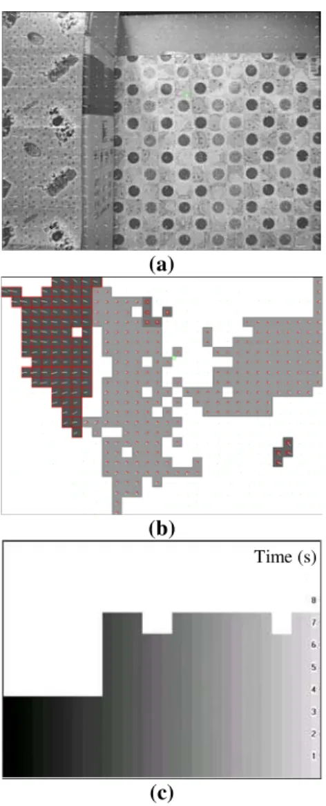
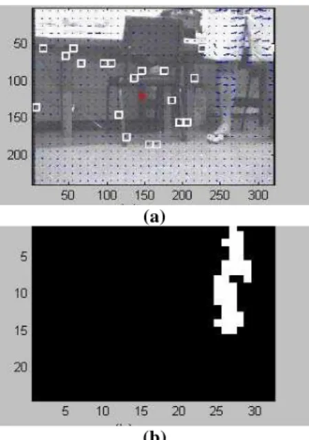
Once the time to contact correspondent to each region in the image is available, the time to contact associated to each ob-ject is obtained by averaging the times to contact correspon-dent to the regions associated to that object. Then, the least time to contact corresponding to each column of the matrix of 24x32 optical flow vectors is obtained, thus filling a vec-tor of 32 positions, whose elements are the values of the least time to contact corresponding to each vertical 10 pixels-wide stripe in the image frame. This is equivalent to define a set of 32 visual sensors, each one measuring the time to contact in an angle of 48.8/32=1.525 degrees in the visual field of the robot. Such a vector, which is graphically depicted in Figure 3, is the sensorial information the sensing system delivers to the control system in order to allow it to define the new head-ing angle to be imposed to the robot to avoid the obstacles in its visual field. Equal values of time to contact in contigu-ous positions of such a vector represent the distance from the robot to a single object in its field of vision. By its turn, dis-tinct values of time to contact correspond to disdis-tinct objects. This way, in part c of Figure 3 it is possible to identify two different objects in the visual field of the robot, whose depths are characterized for the two clearly distinct values of time to contact.
The vector of times to contact and the magnitude of the op-tical flow vector in the regions associated to an object can provide rich information to a control system. In the sensing system here proposed, objects for which the average magni-tude of the optical flow vectors exceed a threshold of 1.2 are understood as objects too close to the robot, thus demanding a more drastic evasive maneuver.
Important information is also provided by the average value and the standard deviation of the components of the vector of times to contact. When the standard deviation is too low, it is very likely that a single object spanning over the entire field
(a)
(b)
Time (s)
(c)
Figure 3: An example of the use of the optical flow-based image segmentation algorithm. In (a) it is shown the first of a set of two image frames acquired at the rate of 30 frames per second. In (b) it is shown the result of the image seg-mentation process (the white regions are those defined as not pertaining to an object in the scene, and the other regions are the objects detected - the darker the region is, the closer the object is). Finally, (c) depicts the vector of times to contact corresponding to such image frame.
of vision of the robot is in front of it. If the average time-to-contact value is also low (below 2.5 s), this means that the object in front of the robot is very close to it. In both cases, to stop the robot is the safest reaction.
consumed to do it, is presented in Section 5, in connection to the discussion of the results of an experiment run.
4
CHECKING THE PERFORMANCE OF
THE PROPOSED SENSING SYSTEM
In this section a state-machine is designed in order to allow checking how the sensing system described in the above sec-tions performs. The robot is programmed to wander around the lab, just avoiding colliding to any obstacle. It reacts to the presence of an obstacle by changing its heading angle from its current value (zero degrees, since the robot is just going ahead) to a new value, which is determined by the sensorial information embedded in the vector of times to contact de-livered by the sensing system here proposed.
Three distinct situations are considered in the implementa-tion of such a state-machine, which are labeled imminent collision ahead, side obstacle and normal situation. Immi-nent collision ahead is characterized either when the average value of the components of the vector of times to contact is below 2.5 s with a standard deviation close to zero (meaning that a wide object is very close to the robot), or when an ob-ject whose average magnitude of the optical flow vectors is greater than the threshold adopted is detected in the middle of an image frame (the elements 9 to 24 of the vector of times to contact). In such cases, the action the robot takes is to go back about 10 cm, to rotate 180 degrees and to move ahead again. Those two situations are illustrated in Figure 4, were a wall is detected in front of the robot, and Figure 5, where the robot gets close to a waving hand, respectively.
Whenever the object whose average magnitude of the optical flow vectors is greater than the threshold value is in the right side (columns 25 to 32) or in the left side (columns 1 to 8) of the visual field of the robot, the situation labeled side obsta-cle is characterized. In such cases, the maneuver adopted is to rotate 15 degrees in the opposite direction and to resume moving ahead. Figure 6 illustrates a case of a side obstacle at the right side of the image frame. If two objects are detected, one in each side of the image frame, however, the system characterizes the situation as imminent collision ahead.
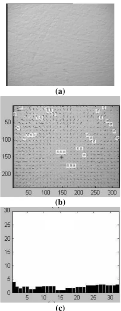
The normal situation is characterized when neither objects with high average optical flow magnitude nor objects span-ning over all the visual field of the robot are detected in the image frame. This means that an abrupt maneuver is not nec-essary. When this is the case, a new small heading angle is determined, the robot turns around its own axis according to such angle and after continues moving ahead. This situation is illustrated in Figure 7, which shows two images collected by the camera onboard the robot. A certain time has elapsed and six deviations have been performed, after getting the two images shown in the figure. From the two images one can
(a)
(b)
(c)
Figure 4: Exemplifying the detection of a wall. Part (a) shows the wall, part (b) shows the optical flow vectors calcu-lated, and part (c) shows the corresponding vector of times to collision.
notice that the robot has deviated a little to the right, firstly because of the chair leg and after because of the table leg, both appearing in the first image and not in the second one.
In this case, the new heading angle to be imposed to the robot is determined according to the proposal discussed in (Sarcinelli-Filho et. al., 2002a). Like there, each element of the vector of times to contact is considered as similar in-formation coming from distinct sensors. The state-machine associates to each sensor an angle, in order to make the robot to deviate of an obstacle detected in such a direction. The angle correspondent to a right turn, for thei-th component of the vector of times to contact, is given by
θri=−
αri
τi+ 1
, fori= 0,1, ...,31, (5)
(a)
(b)
Figure 5: Illustrating the detection of a waving human hand in the middle of the image. The real hand is in (a), while (b) shows the regions whose average optical flow magnitude is higher than the threshold adopted.
columniis, the greater the angleθriis. In a similar way, the angle correspondent to a left turn, for thei-th component of the vector of times to contact, is given by
θli=
αli
τi+ 1
, fori= 0,1, ...,31, (6)
whereαli=k(31−i), kbeing a constant. In opposition to the right turn angles, the more right the columniis, the smaller the angleθliis. In the experiments, the value adopted for the constantkwas 3.
The variances associated to such angles is given by
σ2i =τi, fori= 0,1, ...,31, (7)
and represents an indication of the risk of a collision in the direction corresponding to each sensor, or, in other words, of the relevance of the obstacle in each column of the field of vision of the robot in terms of the robot safety.
The anglesθri andθli, and the respective variances, are in-putted to two distinct decentralized Kalman filter (Brown and Hwang, 1997), which generates the overall left turn and right turn anglesθlandθr, respectively (in the range from -15 de-grees to +15 dede-grees), which are the two candidates to be the new heading angle of the robot. The new value for the robot heading angle is then defined asθ= min(θl,θr).
(a)
(b)
Figure 6: Detecting an object at the right side of the image. The object - a human leg - is in part (a), while part (b) shows the regions whose average optical flow magnitude is higher than the threshold adopted.
(a)
(b)
Imminent collision ahead
Go back Rotate Go ahead command Evaluation
Side obstacle
Calculate heading angle Normal situation
End End
End
Idle Start End
Figure 8: The state-machine corresponding to the control system implemented.
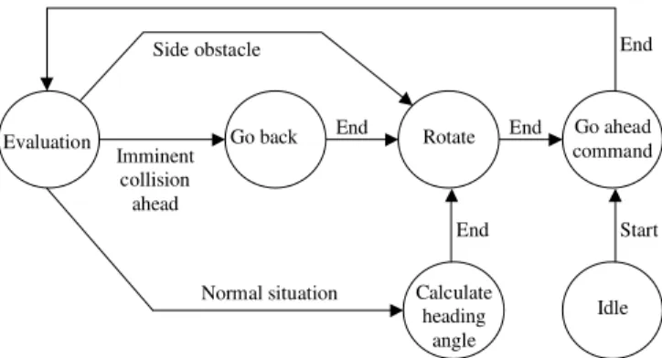
The three maneuvers above described represent the state changes of interest in the state machine implemented, which is depicted in Figure 8. There, all the optical flow calcula-tion and image segmentacalcula-tion, up to generating the vector of times to contact and checking the average optical flow mag-nitudes for the regions pertaining to the objects detected, are performed when the robot gets into the state Evaluation. The other circles in Figure 8 correspond to the three commands above mentioned (to go back 10 cm, to rotate and to move ahead), whose composition implements the above described composite maneuvers.
The state Idle in Figure 8 characterizes the robot state before being started. After the programmer starts the robot, it starts moving ahead, thus entering the state Evaluation. All the calculations necessary to determine the situation the robot is facing (imminent collision ahead, side obstacle or normal situation) are then performed, and, according to the situation, the suitable maneuver is implemented. In the normal situa-tion case, the next state is to calculate the new heading angle (the current heading angle is always zero degrees).
It is also important to mention that the links included in Fig-ure 8 are the only valid possibilities for our purposes. Any other link is not meaningful in the context here considered, and then is not included in the state-machine of Figure 8.
It should be emphasized, in such a context, that the command execution is strictly sequential, as defined by the branches End in Figure 8. Only after the system finishes the calcula-tion of the new heading angle the corresponding turn around can start, as well as only after finishing turning around the robot can start moving ahead again. In particular, the action to move ahead demands that the robot linear speed starts in zero and gets its final value (in this work 100 mm/s), thus demanding a certain time to be accomplished. Hence, the image frames used in the optical flow calculation are always acquired when the robot is performing pure translation, thus
guaranteeing that the FOE is always in the image, a necessary condition to calculate any time to contact.
5
EXPERIMENTAL RESULTS
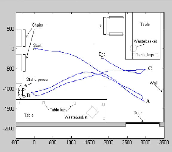
In order to check the performance of the sensing subsystem discussed in Sections 2 and 3, under the coordination of the state-machine discussed in Section 4, an experiment is now presented and discussed. The robot is programmed to wan-der around in the lab, avoiding all the chair legs, table legs, people legs, walls, etc., it detects. Figure 9 shows the path the robot followed during its navigation. The layout of the lab has been over imposed to the figure in order to allow an-alyzing the maneuvers the robot performed.
In such a figure one can see that the robot stopped and ro-tated 180˚ when facing either a wall or a static person (points A, B, and C). All the remaining time the maneuvers executed corresponds to the normal situation. An analysis of all the ac-tions the robot took shows that it was effectively able to avoid the obstacles that appeared in its way, as expected, using only the optical flow-based sensorial information, packed on the vector of times to collision discussed in Section 3. Other ex-amples have also shown that using optical flow it is possible to detect the movement of people inside the lab, which sug-gests the possibility of using such sensing system to follow a person, for example.
In addition to Figure 9, Table II shows the times correspond-ing to the definition of the new headcorrespond-ing angle and to the exe-cution of the evasive maneuvers defined some times the robot got into the state Evaluation. There, a negative angle means a turn to the right, while a positive angle means a turn to the left. Also, the movements the robot executes are the compo-sition of going back 10 cm, rotating 180˚ and going ahead (lines 5, 8 and 11 of the table) and the composition of rotat-ing much less than 180˚ and gorotat-ing ahead (the other lines of the table), as discussed in connection to Figure 8. By to go ahead, one should understand that the robot goes ahead, ac-cording to the new heading angle established, and its linear speed increases up to 100 mm/s, which consumes the time specified in Table II (about 1 s).
As one can see, the time corresponding to the acquisition of two image frames, the calculation of the optical flow vectors plus the calculation of the new heading angle is compatible with the robot dynamics, thus showing that the use of optical flow for this kind of sensing is suitable, which is one of the contributions of this paper.
ac-A
B
C
Figure 9: The path followed by the robot while wandering (distances are in mm).
quisition rate. In addition, each image acquisition, included in the state Evaluation shown in Figure 8, corresponds to the acquisition of two subsequent image frames, and the time to capture both frames is also not constant. It depends on the processes being executed in the onboard computer (a Win-dows ME computer).
Another important result, regarding the time table corre-sponding to the experiment, is summarized in Table III. It illustrates the time spent to acquire the two image frames, to calculate the optical flow vectors, to generate the vector of times to collision, and to compare the average optical flow magnitudes correspondent to the different objects detected in the scene to the threshold adopted, for the same time in-stants registered in Table II. From such table, one can see that the most time consuming step of processing involved in the sensing subsystem is just the acquisition of the two image frames used to determine the optical flow vectors. Thus, the restriction on the number of image frames used by the algo-rithms for optical flow calculation is absolutely necessary, if one wants to reduce the time spent to get the sensorial
infor-mation, as well as any attempt to improve the system reactiv-ity should address a drastic change in the image acquisition procedure.
Other meaningful feature emerging from the analysis of Ta-ble II and TaTa-ble III is that the whole time spent in the sensing subsystem processing is different in the two tables, which is due to the fact that such measures are performed in two distinct threads of the software corresponding to the system implementation, so that the measure presented in Table II in-cludes the necessary passage of parameters from one to the other thread.
6
CONCLUSION
Table 3: The time table corresponding to the computations involved in the sensing subsystem.
Image Acquisition
(ms)
Optical Flow Calculation
(ms)
Image Segmentation
(ms)
Determination of the FOE Coordinates
(ms)
Analysis of Characteristics
(ms)
Calculation of the New Heading Angle (ms)
Total (ms)
99 44 6 2 2 8 161
53 44 6 1 3 7 114
62 44 6 1 2 8 123
60 50 6 2 2 - 121
72 43 6 2 2 7 132
52 43 6 2 2 7 112
81 44 6 1 2 - 134
56 44 8 1 2 7 118
75 44 6 1 2 7 135
79 44 6 1 2 - 132
Table 2: The time-table corresponding to the experimenta-tion.
Time to acquire two image frames and to deter-mine the
new heading
angle (ms)
Time to go back 10 cm
(ms)
Time to rotate
(ms)
Rotation angle
(de-grees)
Time to go ahead
(ms)
178 - 592 -3 1004
124 - 1071 10 1006
131 - 733 7 1006
130 1005 2590 180 1005
141 - 504 6 1010
115 - 1020 12 1005
137 1003 2584 180 1006
121 - 1018 -10 1011
138 - 721 -4 1006
135 1005 2474 180 1007
a decision on how much it should vary its current heading angle in order to avoid the closest obstacles in its visual field.
The two main paradigms in the conception of such a sensing system were the full onboard calculation and the guarantee that the robot were able to react to any environmental change in real-time. Such aims were effectively accomplished, as showed in the experiment reported.
As a result of the analysis of the experiments run, it is pos-sible to conclude that the use of optical flow to implement reactive strategies for mobile robot navigation is viable. Ac-tually, in the implementation here proposed it is shown that the main problem is not the computation time associated to the optical flow, time to contact or heading angle calculation, but the time consumed during the image acquisition.
7
ACKNOWLEDGEMENTS
The authors thank CNPq – National Council of Scientific and Technological Development, a Brazilian governmental institution promoting the scientific and technological devel-opment, for granting this research.
They also thank CAPES (Brazil) and SECyT (Argentina) for funding a partnership between Universidade Federal do Es-pírito Santo, Brazil, and Universidad Nacional de San Juan, Argentina, in which this work is included. As part of this partnership, Mrs. Eliete M. O. Caldeira got a scholarship to spend three months in San Juan, Argentina, working in this project.
REFERENCES
Adams, R. and Bischof, L., (1994). Seeded Region Grow-ing.IEEE Transactions on Pattern Analysis and Ma-chine Intelligence, vol. 16, pp. 641-647, June.
Ancona, N. and Poggio, T., (1995). Optical Flow from 1D Correlation: Application to a Simple Time-to-Crash Detector. International Journal of Computer Vision, vol. 14, pp. 131-146.
Baratoff, G., Toepfer, C. and Neumann, H., (2000). Com-bined Space-Variant Maps for Optical Flow Based Nav-igation.Biological Cybernetics (Special Issue on Navi-gation in Biological and Artificial Systems), vol. 83, pp. 199-209.
Batavia, P. H., Pomerleau, D. A. and Thorpe, C. E., (1998). Overtaking Vehicle Detection Using Implicit Optical Flow.Proceedings of the IEEE Conference on Intelli-gent Transportation Systems, pp. 729-734.
Barraquand, J., Langlois, B. and Latombe, J. C., (1992). Nu-merical Potential Field Techniques for Robot Path Plan-ning.IEEE Transactions on Systems, Man, and Cyber-netics, vol. 22, pp. 224-241.
Barron, J. L., Fleet, D. J. and Beauchemin, S. S., (1993). Performance of Optical Flow Techniques.International Journal of Computer Vision, vol. 12, number 1, pp. 43-77.
Barron, J. L. and Liptay, L., (1997). Measuring 3D Plant Growth Using Optical Flow.BioImaging, vol. 5, pp. 82-86.
Bergen, J. R., Burt, P. J. and Hanna, K., (1992). Dynamic Multiple-Motion Computation. Artificial Intelligence and Computer Vision, Elsevier, The Netherlands, pp. 147-156.
Bleau, A. and Leon, L. J., (2000). Watershed-Based Seg-mentation and Region Merging.Computer Vision and Image Understanding, vol. 77, pp. 317-370.
Borshukov, G. D., Bozdagi, G., Altunbasak, Y. and Tekalp, A. M., (1997). Motion Segmentation by Multi-Stage Affine Classification.IEEE Transactions on Image Pro-cessing, vol. 6, number 11, pp. 1591-1594, November.
Brooks, R. A., (1986). A Robust Layered Control System for a Mobile Robot.IEEE Journal of Robotics and Au-tomation,vol. 2, pp. 14–23, March.
Brown, R. and Hwang, P., (1997). Introduction to Ran-don Signals and Applied Kalman Filtering, 3rd edition, John Wiley & Sons, New York, USA.
Carelli, R., Soria, C., Nasisi, O. and Freire, E. (2002). Sta-ble AGV Corridor Navigation with Fused Vision-Based Control Signals. Proceedings of the IEEE 2002 28th Annual Conference of the Industrial Electronics Soci-ety - IECON 02, Sevilla, Spain, vol. 3, pp. 2433-2438, November.
Camus, T., Coombs, D., Herman, M. and Hong, T. H. (1999). Real-time Single-Workstation Obstacle Avoidance Us-ing Only Wide-Field Flow Divergence.Videre: Journal of Computer Vision Research, MIT Press Journals, vol. 1, pp. 30-57.
Coombs, D., Herman, M., Hong, T. and Nashman, M., (1998). Real-time Obstacle Avoidance Using Central Flow Divergence and Peripheral Flow.IEEE Transac-tions on Robotics and Automation, vol. 14, pp. 49-59, February.
Dev, A., Kröse, B. J. A. and Groen, F. C. A., (1997a). Navigation of a Mobile Robot on the Temporal De-velopment of the Optic Flow.Proceedings of the 1997 IEEE/RSJ/GI International Conference on Intelligent Robots and Systems (IROS’97), Grenoble, France, pp. 558-563, September.
Dev, A., Kröse, B. J. A. and Groen, F. C. A., (1997b). Con-fidence Measures for Image Motion Estimation. Pro-ceedings of the 1997 RWC Symposium, Japan, pp. 199-206.
Farah, M. J., (2000).The Cognitive Neuroscience of Vision – Fundamentals of Cognitive Neuroscience, Blackwell Publishers Inc., USA.
Giachetti, A., Campani, M. and Torre, V., (1998). The Use of Optical Flow for Road Navigation. IEEE Transac-tions on Robotics and Automation, vol. 14, pp. 34-48, February.
Grossmann, E. and Santos-Victor, J. A., (1997). Performance Evaluation of Optical Flow Estimators: Assessment of a New Affine Method.Robotics and Autonomous Sys-tems, Elsevier, The Netherlands, vol. 21, pp. 69-82.
Horn, B. K. P. and Schunck, B. G. (1981). Determining Op-tical Flow.Artificial Intelligence, vol. 17, pp. 185-203.
Lai, S. H. and Vemuri, B. C., (1998). Robust and Efficient Computation of Optical Flow.International Journal of Computer Vision, vol. 29, pp. 87-105.
Lucas, B. and Kanade, T., (1981). An Iterative Image Regis-tration Technique with an Application to Stereo Vision. Proceedings of DARPA IU Workshop, pp. 121-130.
Nesi, P., Del Bimbo, A. and Ben-Tzvi, D. (1995). A Ro-bust Algorithm for Optical Flow Estimation.Journal on Computer Vision, Graphics and Image Processing: Im-age Understanding, Academic-Press, vol. 61, number 2, pp. 59-68.
Ramel, G. J. L., (2000). The Incredible World of Mammals The Sensory World of Mammals – Sight and Vision -Sight and the Mammal Eye.The Earth Life Web, avail-able in http://www.earthlife.net/mammals/vision.html, downloaded in April.
Santos-Victor, J. A., Sandini, G., Curotto, F. and Garibaldi, S., (1995). Divergent Stereo in Autonomous Naviga-tion: From Bees to Robots. International Journal of Computer Vision, vol. 14, pp. 159-177, March.
Sarcinelli-Filho, M., Schneebeli, H. J. A., Caldeira, E. M. O. and Soria, C. M. (2002a). Optical Flow-Based Obstacle Detection and Avoidance in Mobile Robot Navigation. Proceedings of the 10thIEEE Mediterranean Confer-ence on Control and Automation – MED2002, in CD, Lisbon, Portugal, July.
Sarcinelli-Filho, M., Schneebeli, H. J. A., Caldeira, E. M. O., (2002b). Using Optical Flow to Control Mobile Robot Navigation.Proceedings of the 15thWorld Congress on Automatic Control, Barcelona, Spain, July.
Stöffler, N. O., Burkert, T. and Färber, G., (2000). Real-Time Obstacle Avoidance Using an MPEG-Processor-Based Optic Flow Sensor. Proceedings of the 15th Interna-tional Conference on Pattern Recognition, vol. 4, pp. 161-166, Barcelona, Spain, September.
Tekalp, A. M., (1995).Digital Video Processing, Prentice-Hall, Englewood Cliffs, NJ, USA.
Wallach, D. S., Kunapalli, S. and Cohen, M. F., (1994). Ac-celerated MPEG Compression of Dynamic Polygonal Scenes,”Computer Graphics (Proceedings of the ACM SIGGRAPH 1994), Orlando, FL, USA, pp. 193-196.