*e-mail: [email protected]
Photo-assisted Electrochemical Copper Removal from Cyanide Solutions
Using Porous TiO
2Thin Film Photo-anodes
Álvaro A. Ramírez-Santos, Próspero Acevedo-Peña, Elcy M. Córdoba*
Grupo de Investigaciones en Minerales Biohidrometalurgia y Ambiente, Universidad Industrial de Santander – UIS, Calle 9 Cra. 27, Postal Code 678, Bucaramanga, Santander, Colombia
Received: November 14, 2012; Revised: July 24, 2013
TiO2 porous ilms were prepared on ITO coated glass slides by the sol‑gel dip‑coating method assisted with Polyethylene glycol (PEG). The ilms were used as photo‑anodes in the photo‑assisted electrolytic removal of cuprous ions in cyanide media. These were characterized by SEM, UV‑Visible spectroscopy and XRD. The PEG modiied ilms were free of cracks and developed a porous structure after heat treatment at 500 °C, due to the thermal decomposition of the structure associated PEG. It was demonstrated that the photo‑assisted electrochemical reduction of copper is promoted by the use of modiied TiO2 ilms as photo‑anodes, thanks to the greater surface area given by the PEG decomposition. However, the ilm thickness was found to be a critical factor in the process, to such an extent that ilms composed of 5 layers were completely ineficient, meaning that despite the open porosity, multilayered ilms acted as a barrier within the photo‑electrolytic process.
Keywords: porous TiO2 thin films, sol-gel dip-coating, polyethylene glycol (PEG), photo-assisted electrolysis, copper ion removal
1. Introduction
Titanium dioxide (TiO2) offers an excellent chemical stability over a wide pH range and in an elevated number of solvents. Furthermore it presents a high chemical resistance under illumination (low photo‑corrosion) and possesses the advantages of being non‑toxic, safe, relatively abundant and, because of the high oxidizing power of the holes in its valence band, it has the capacity to completely mineralize most of the pollutants of industrial concern. All these properties make the TiO2 the material chosen by excellence for photo‑catalytic applications1.
In recent years, an important part of the applications of the titanium dioxide has been focused on the puriication and treatment of aqueous and gaseous currents contaminated by organic compounds and/or metallic ions employing particulate TiO22-13. Specially, the metal ions removal has received certain attention due to the feasibility of valuable metals recuperation7,9,12. The metal ions present in efluents are usually found to be complexed by substances like EDTA or Cyanide, species widely employed for industrial applications. The photo‑catalytic treatment of these solutions showed several problems. For example, whereas the EDTA oxidation is achieved, the metal ions reduction is not attained9. On the other hand, when cyanide complexes are present, normally it is required to add a hole scavenger (generally an alcohol) to enhance the metal complex reduction, inhibiting the oxidation of CN–, resulting in an undesirable accumulation of such toxic species in the solution7.
Although the results obtained with particulate materials have shown that the heterogeneous photo‑catalysis is
a promising alternative for remediation of that type of efluents, they have also revealed disadvantages related with the separation, recovery and recycling of the catalyst and metallic deposits from the treated efluents4,5,14. An
alternative and effective methodology to overcome these inconveniences is the photo‑assisted electrolysis11. Here, the TiO2 is supported on a conductive substrate to be used as anode and is coupled with a conductive material acting as a cathode. In this system, the metals ions are reduced over a metallic electrode allowing its recovery, or just making easier its disposal. Additionally, due to the imposed potential, oxidation of the complex forming agent can occur at the photo‑anode, avoiding the hole scavenger addition in the solution15.
One of the most common methodologies for the elaboration of supported TiO2 on conductive substrates is the combination of the Sol‑gel process and the dip‑coating or spin‑coating techniques16, due to the low sintering temperatures required, versatility of the processes and homogeneity at molecular level17. However, the films obtained by this technique are generally cracked and present low surface area related to its low porosity18. Recent studies19-22, have pointed out the use of certain compounds called polymeric fugitive agents (PFA’s) as generators of porosity, which are able to produce, after heat treatments and without obstructing the gelation, porous crack‑free ilms that lead to photo‑electrolytic activities superior to those of traditional ilms. Among the different PFA’s employed in the literature, polyethylene glycol has some advantages such as its relatively low cost, low toxicity and molecular weight range available23. Additionally, it has shown to provide TiO
In this study, a simple methodology for the preparation of TiO2 porous thin ilms supported on conductive glass slides was developed, using PEG as polymeric fugitive agent. The ilms were characterized by X‑ray diffraction, UV‑Visible spectroscopy and scanning electron microscopy. Finally, the effects of PEG modiication and the number of deposited layers on the photo‑assisted electrolytic removal of copper in cyanide solutions were studied.
Cyanide baths are commonly employed during copper electroplating due to some advantages over other bath compositions, such as highly adherent, uniform and ine‑ grained deposits23. However, waste water coming from these industries are poisonous, representing a risk for human live and the environment23,26-28. There are different methodologies applied for removal the cyanide ions and recovery the copper ion in waste waters23,26-28, unfortunately photo‑catalysis has receive minor attention despite its advantages of being a environmentally friendly and low cost methodology26. In the present study we take advantage of the photocatalysis and electrolysis to oxidize the cyanide ions and simultaneously recover the copper on a metallic substrate23,26.
2. Experimental
2.1.
Preparation of TiO
2sols
The titania sols were prepared using titanium tetraisopropoxide (97%, Aldrich) as TiO2 precursor, isopropanol (98%, Carlo Erba) as solvent, acetylacetone (99%, Aldrich) as stabilizer, acetic acid (100%, Merck) as pH adjuster and granular polyethylene glycol (Carbowax) with molecular weight of 3350 as template agent for pore formation. The sols were prepared at room temperature, in the following order: First, 2.6 mL of acetylacetone was added to 12.5 mL of isopropanol under constant stirring for 30 minutes. Then 5 mL of titanium tetraisopropoxide was added to the above solution and the mixture was maintained under stirring for 30 minutes. Deionized water was slowly added, drop by drop, and the solution was maintained under stirring for an extra 15 minutes. Finally, the pH was adjusted to 4 with acetic acid and polyethylene glycol was added in a concentration of 24 g/L for modiied ilms. The sols were maintained under stirring for two hours. At this stage, the effect of the PEG addition on the stability and viscosity of the sols with time was evaluated. Such stability was evaluated in a qualitative manner, registering whether precipitates were present or not. The thermal analyses (TGA and DTG) were carried out on xerogels obtained after the desiccation of the sols at 50 °C for 24 hours. These analyses were performed at a heating rate of 5 °C/min under oxidizing atmosphere, with an air lux of 20 mL/min.
2.2.
Preparation of TiO
2photo-anodes
Glass slides covered with an Indium‑Tin Oxide conductive layer (Aldrich 8‑12 Ω/Sq) were used as substrates. The substrates dimensions were 25 mm × 15 mm × 1 mm. Before immersion, the substrates were washed with isopropanol for 30 minutes in an ultrasonic bath and were dried at room temperature under an air lux. TiO2 layers were deposited by immersion‑extraction (dip‑coating) on
the corresponding sol at 10 cm/min. After deposition, the ilms were dried at room temperature in a dessicator for three hours and were heat treated at 500 °C for one hour with a heating rate of 5 °C/min. The process was cyclically repeated for each deposited layer. The number of deposited layers in each sample varied from 1 to 5 layers and, for the purpose of this study, the samples with 1, 3 and 5 layers were chosen for analysis.
The effects of the PEG addition and of the number of deposited layers on the optical, crystalline and morphologic properties were evaluated by means of the following techniques: UV‑Visible spectroscopy in the 200‑800 nm range, X‑Ray diffraction using CuKαradiation operating at 40 kV and 40 mA, and Scanning electron microscopy operating between 5 and 15 kV.
2.3.
Photo-assisted electrolytic reduction of
cuprous ion in cyanide solutions
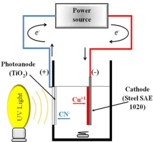
The photo‑electrolytic reactor used in this study (Figure 1) consisted of a prismatic compartment with a squared base and a capacity of 50 mL of solution. The photo‑anode was placed in one side of the reactor in order to illuminate the TiO2/electrolyte interface through a window, employing a high pressure mercury lamp (General Electric, Kolorlux, 125 W), placed at 2 cm from the photo‑anode surface. In addition to 365 nm as its main line spectrum, other line spectra emitted are: 254 nm, 313 nm, 405 nm, 436 nm, 546 nm and 579 nm. The cathode was placed inside the solution and was separated from the photo‑ anode by a distance of 2.5 cm. It consisted of a steel sheet (AISI SAE 1020) of 40 mm × 20 mm × 1 mm. For all experiments the voltage between electrodes, applied by a power source, was 2.5 V. The reaction volume for all experiments was 50 mL of an 1800 ppm solution of Cu+1 at pH 10 and with a CN– :Cu+1 molar ratio of 3:1. Such concentrations and pH values are commonly found in the wastewaters of industrial electroplating processes. The
solution was stirred during all the reaction period (2 hours) to promote the homogeneity of the reaction volume. Before the tests, the solution was kept at dark for 15 minutes in order to smooth the humectation progress of the photo‑anode. The copper concentration was followed by atomic absorption spectroscopy on samples taken along the reaction time.
3. Results and Discussion
3.1.
Polyethylene glycol effect on the viscosity
and stability of the TiO
2sols
The variation of the sols viscosity with time (with and without PEG) is presented in Figure 2. There is a slight but constant increase of the viscosity of the sols with time. This behavior is a response to the progress of the hydrolysis and condensation reactions that take place inside the sol29. Normally, during the aging of the sol a sharp increase on the viscosity is observed, but in this case the presence of acetylacetone diminishes the velocity of the gelation reactions30,31, which is relected on the smooth increase of viscosity. The PEG addition also generates an increase of 0.84 cP on the initial viscosity of the sol, as a result of the thickening properties of the polymer32. The presence of PEG did not affect the stability of the sol, as they remained translucent and without displaying precipitates, which is an important factor for achieving transparent TiO2 ilms.
3.2.
Thermal analysis of the Xerogels obtained
from the TiO
2sols
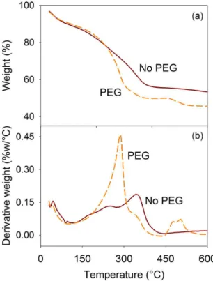
The Xerogels thermogravimetric analysis, recorded up to 600 °C, is presented on Figure 3a. The PEG modiied TiO2 xerogel underwent a bigger weight loss than the unmodiied xerogel, with values of 54.4% and 44.7% for the samples with and without PEG respectively. In both cases the biggest weight loss occurred up to 400 °C approximately, which allows to conclude that under this temperature the decomposition of the organic products was produced.
The differential thermograms (see Figure 3b) show a peak between 30 °C and 100 °C, caused by desorption of water. A pronounced peak is observed between 200 °C
and 300 °C for the PEG system and, between 300 °C and 400 °C for the system without PEG. These peaks correspond to pronounced weight losses; hence they are attributed to the organic components combustion such as the solvent, stabilizer, alcoxide and the PEG33. The PEG modified xerogel showed a small peak between 450° and 500 °C, related to residual organic compounds within the sample.
3.3.
TiO
2films characterization
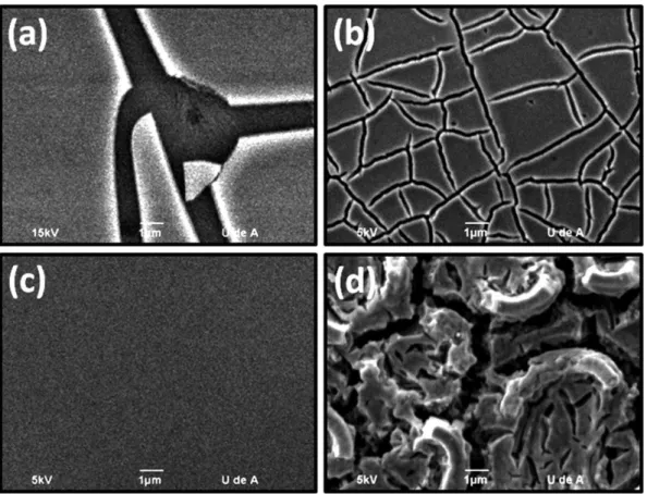
Figure 4 shows the SEM images for ilms with 1 and 5 layers prepared with and without PEG. The TiO2 ilms without PEG present a plane and cracked morphology, as product of their contraction during heat treatment; this cracking increases with the number of layers or the thickness of the coating. On the other hand, the ilms prepared in the presence of PEG are free of cracks, and due to the polymer decomposition during heat treatment (between 200 and 300 °C), developed a porous structure. The perceptible cracks for the 5 layered ilm (Figure 4d) are really pores interconnections that grow in quantity and size with the increase in the number of layers.
XRD analyses for the 5 layered TiO2 ilms with and without PEG are presented in Figure 5. As for all thin ilms, the peaks are not very intense because of the low quantity of material deposited and the size of the crystallites33. For the diffractograms of both ilms, the most representative peak is situated in the region of 25° and corresponds to the (101) plane of the anatase, typically found for ilms treated at 500 °C34. The diffractogram of the PEG modiied ilm shows
Figure 2. Viscosity vs. Time for the TiO2 sols with and without PEG.
the same peaks of the unmodiied ilm, and the intensity is also similar, which is an evidence that the polyethylene glycol does not intervene in the crystallization process at the temperature selected for heat treatment, as reported by other authors19. Additionally, employing the Scherrer equation to estimate the crystallite size of the TiO2 in the ilms11,35, considerable differences were not found by adding
PEG as modifying agent: 17.9±2.0 nm and 13.2±1.2 nm for
TiO2 ilms without and with PEG respectively. Conirming that PEG is only affecting the surface area of the ilm (see Figure 4).
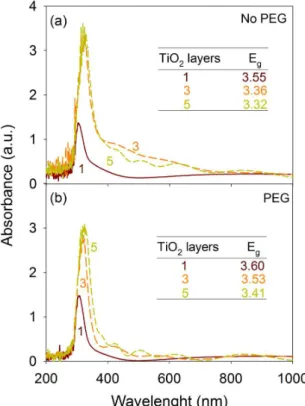
Figure 6 presents the UV‑Visible spectra for ilms with 1, 3 and 5 layers with and without modiication with PEG supported on ITO glass slides. In all cases, a strong UV absorption band is observed between 300 and 400 nm, characteristic for the TiO236. The same behavior of the ilms with the number of layers is observed in both types of ilms. As the number of layers increases, the ilm becomes less transparent due to the increase of deposited material, what translates into greater absorption intensities of the ilms within the UV region.
The band‑gap energies of the TiO2 ilms were estimated from their UV‑Vis spectra (see Figure 6). The red‑shift of the absorption edge of the TiO2 ilms produced by the increase in the number of layers involves a decrease of the band‑gap energies (Eg) from 3.55 eV (1 layer) to 3.32 eV (5 layers) for unmodiied TiO2 ilms and from 3.60 eV (1 layer) to 3.41 eV (5 layers) for ilms modiied with PEG. However, due to the small shift observed in the band‑gap energies, it can be assumed that the use of PEG to obtain porous TiO2 ilms, does not modify the TiO2 electronic structure, or induces states inside the band‑gap of the semiconductor.
3.4.
Photo-assisted electrolytic removal of copper
3.4.1. Effect of the PEG and illumination
Figure 7 shows the effect of illumination on the electrolytic removal of copper, using the 1 layered TiO2 Figure 4. SEM images of the surface of the TiO2 photo‑anodes with 1 (a) and 5 (b) layers without PEG, and 1 (c) and 5 (d) layers with PEG.
Figure 5. Diffractograms for the Substrate (ITO glass) and for the 5 layered TiO2 ilms heat treated at 500 °C. Letter A indicates the
and photo‑assisted electrolysis processes, going from 0.2% (no PEG) to 12% (with PEG) of copper removal for the electrolysis and from 15% (no PEG) to 20% (with PEG) for the photo‑assisted electrolysis. This effect is related to the porosity generated in the TiO2 ilms by the PEG as showed in Figures 4c, d.
The greater photo‑anode’s porosity implies a greater surface area, hence, a greater number of active sites where anodic reactions occur. The anodic reactions implied in the process are the following37:
2 2( )
hv
TiO →TiO h++e− (1)
2
2 2
CN−+ OH−+ h+→CNO−+H O (2)
2
3 2 2
2CNO−+8OH−+6h+→2CO −+N +4H O (3)
2 2
4OH−+4h+→O +2H O (4)
The OH− and CN− ions present in solution take
rapidly the h+ from the TiO
2, diminishing in this way their recombination with the photo‑generated electrons; these electrons diffuse through the TiO2 ilm until they arrive to the conductive substrate, where they are transported by the external electric circuit to the cathode. On this electrode, the photo‑generated electrons (Reaction (1)) catalyze the copper complexes reduction reactions, especially the reduction of Cu(CN)32− which is the most abundant for the Cu+1–CN−
system according to the speciation diagrams (igure not showed here)37,38, as well as the formation of hydrogen as additional reaction:
2 0
3 2
2Cu CN( ) −+e−→Cu +Cu CN( )−+4CN− (5)
0 2
( ) 2
Cu CN−+e−→Cu + CN− (6)
2 2
2H O+2e−→H +2OH− (7)
The extent of the electrolytic and photo‑assisted electrolytic removal of copper is related with the current generated in the process. The differences in the current behavior for each of the tests are presented in Figure 8. The higher initial currents (4.5 and 4.7 mA) correspond to the electrolysis and photo‑assisted electrolysis tests with PEG modiied TiO2 photo‑anodes, which relates to their higher surface area. Additionally, the higher currents after two hours of reaction (7.3 mA) correspond to the photo‑assisted electrolysis tests, caused by the catalytic effect of the UV radiation (photo‑generated current), independently of the modiication of the photo‑anode with PEG.
An additional phenomenon is presented in curves showed in Figure 8, in which an increase and following decrease on the measured current is observed with time during the electrolysis (only for TiO2 modiied with PEG) and photo‑assisted electrolysis.
A similar behavior has been reported for photo‑catalytic gold recovery from cyanide solutions, where a delay time is necessary to initiate the reduction with the metal ion on the TiO27. In this case, the improvement in the reduction rate
Figure 6. UV‑Vis absorption spectra for the TiO2 ilms with different
number of layers: (a) no PEG, (b) with PEG. The Eg values estimated
for the TiO2 ilms are indicated in each igure.
Figure 7. Copper removal for the 1 layered TiO2 ilms without and
under illumination.
ilms. It is observed that when the unmodiied TiO2 ilm is employed as anode in the electrolysis, the copper removal is negligible (0.2%). However, when the TiO2 film is irradiated with UV light, reduction of cuprous ion increases considerably, reaching 15% of metal removal in solution after 2 hours; this response shows that under illumination, the generation of e−–h+pairs on the TiO
2 ilms promotes the redox reactions taking place on the electrolysis cell.
of gold was attributed to an enhancement in the separation of the photo‑generated electron‑hole pairs, induced by the presence of gold clusters on the semiconductor surface. Nevertheless, in our case, the reduction of copper is expected to occur in the cathode and no or negligible reduction of copper is expected at the TiO2 surface.
On the other hand, this behavior can be attributed to the formation of a thin ilm of Cu on the cathode during the early stages of electrolysis, which facilitates the electronic transfer, causing the observed increase in current observed in Figure 839. The absent of the current increase for the current transient of unmodiied TiO2 ilm in the dark, Figure 8, shows that there is no considerably copper removal, and light is necessary in order to carry the cyanide oxidation and copper reduction in a measurable extension, agreeing with the results in Figure 7 and the formation of a current maximum in the Figure 8. In contrast, for TiO2 ilms modiied with PEG the current increase is observed during electrolytic copper removal (Figure 8), due to the enlargement of TiO2 ilms surface area (Figure 4). The increment of the anode’s surface area carries with it an increase of the electron low from the anode to the cathode, which yields a higher electric charge transference (greater area under the I vs. Time curve) and hence, a higher copper removal. Additionally, when the TiO2 ilm modiied with PEG is illuminated, higher currents are observed together with a decrease in the time necessary to reach a maximum in the current, indicating that in these ilms a synergistic effect between surface and light is taking place to increase the copper removal (Figure 7).
3.4.2. Monitoring of photo‑assisted electrolytic
reduction of copper
The evolution of the Cu+ concentration in solution and current with time is presented in Figure 9. The copper removal velocity diminishes at low concentration values as deduced from the slope of the concentration curve. The concentration proile during the process can be represented as an exponential function40:
0exp( )
C=C −kt (8)
Figure 8. Current vs. Time curve for copper reduction: Electrolysis
with TiO2 ilms without (□) and with PEG (○) and photo‑assisted
electrolysis without (■) and with PEG (●).
Figure 9. Copper concentration and measured current for 8 hours of reaction. The photo‑assisted electrolysis was carried out with a 1 layered PEG modiied TiO2 photo‑anode.
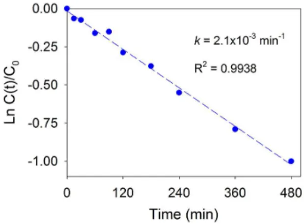
Figure 10. Ln(C/C0) vs. Time (●) experimental data, and (‑‑‑) linear
it. The kinetic constant was derived from the slope of the linear it to the experimental data. 9.
Hence, the photo‑assisted electrolytic removal of copper is a pseudo‑irst order reaction and the kinetics can be expressed as:
0
lnC kt
C = − (9)
Figure 10 presents the ln (C/C0) vs. Time curve obtained by linear regression, with R2 = 0.994. The slope of the line, equivalent to the kinetic constant (k) is equal to 2.1 × 10⁻³ min−1. This value is among the common range of
the photo‑catalytic reactions41. This behavior matches the current evolution with time, presenting high values at short times (with a maximum current of 8.15 mA) and decreasing continuously with time. In spite of this kinetic behavior (diffusion control of reagent and products in the interface), the photo‑assisted electrolytic removal of copper reached 63% after 8 hours.
3.4.3. Effect of the number of TiO2 layers on the
photo‑anode in the photo‑assisted electrolytic removal of copper
increase in the number of layers on the ilm (Figure 11). Conversely, such increase in film thickness causes a detriment in the copper removal, the latter being practically negligible for ilms with 5 deposited layers. This behavior is noticed for PEG modiied TiO2 as for the unmodiied TiO2.
The explanation of the results in Figure 11 can be deduced from current transient presented in Figure 12. It can be observed that for both, the modiied and unmodiied TiO2 photo‑anodes, the electrical current drops with the increase of deposited layers reaching very low values for the ilms with 5 layers which correlates to the negligible copper removal for these ilms (Figure 11). As the number of layers increases, the potential drop throughout the ilm also increases, and the imposed potential (2.5 V) is not enough to accomplish the copper reduction. This phenomenon is also associated to the charge carrier recombination increase with the thickening of the film, as has been proposed by researchers43-47. Porous TiO
2 ilms are made of interconnected nanoparticles that are too small to support a space charge layer inside of them, making the diffusion of e– trough the ilm the only way to transport the photo‑ generated charge carriers. When the TiO2 ilm is biased, an internal potential distribution can be presented, whose extension depends on the ilm thickness and the imposed potential magnitude. This electric ield acts as a sink for photo‑generated electrons, favoring its transport towards rear contact. In thin ilms, the potential distribution can be presented within the whole ilm, allowing the charge carriers separation that causes an increase in the currents and copper removal values. On the other hand, when the thickness of TiO2 ilms is increased, the potential distribution inside the ilm is only presented in a small zone and near to the ITO substrate, so the recombination inside the ilm is increased, causing a detriment in his performance as photo‑anode. Additionally to the recombination process inside the ilm, in the solution are also present oxidizing species (like oxygen and Cu(CN)32−) that can perform as electron scavengers,
especially in the outermost part of the ilms, where the imposed potential is not high enough to favor the electron diffusion towards the ITO substrate.
The former results allow us to propose that the photo‑ electrolytic removal of copper using porous TiO2 ilms as photo‑anodes is also controlled by the electric charge transport, especially for multilayered thick ilms. However, further efforts to comprehend and optimize this type of cells are still needed.
4. Conclusions
The PEG has proved to be an adequate polymeric fugitive agent for the generation of porous TiO2 thin ilms by the sol‑gel process. The modiication of the TiO2 sol with PEG not only enables the formation of a highly porous structure, but also prevents the appearance of cracks on the ilms during heat treatment.
The electrolytic and photo‑assisted electrolytic copper removal processes are favored by the use of porous TiO2 thin ilms as anodes or photo‑anodes respectively. This inluence is related to enlargement in the surface area given by the open porosity generated by the PEG. Nevertheless, Figure 11. Copper photo‑electrolytic removal for TiO2 photo‑
anodes versus number of deposited layers for unmodiied and modiied ilms.
Figure 12. Current vs. Time for TiO2 photo‑anodes versus number
despite that the increase of TiO2 layers on the ilms might induce a higher surface area, these ilms acted as barriers for electron transport, causing a detriment on the eficiency of the process. Consequently, the copper removal is practically absent for ilms with 5 deposited layers.
Acknowledgements
This work has been carried out with the inancial support of COLCIENCIAS (Project 1102‑521‑28875) and UIS (DIEF Ingenierías Fisicoquímicas, Projects 5430 and 9416).
References
1. Lee AC, Lin RH and Yang CY. Preparations and characterization of novel photo‑catalysts with mesoporous titanium dioxide (TiO2) via a sol–gel method. Materials Chemistry Physics. 2008; 109(1‑2):275‑280. http://dx.doi.org/10.1016/j. matchemphys.2007.11.016
2. Pedraza‑Avella JA, Acevedo‑Peña P and Pedraza‑Rosas JE. Photo‑catalytic oxidation of cyanide on TiO2: An
electrochemical approach. Catalysis Today. 2008; 133-135:611‑618. http://dx.doi.org/10.1016/j.cattod.2007.12.063 3. Vohra MS and Davis AP. TiO2‑Assisted photo‑catalysis of
lead–EDTA. Water Research. 2000; 34(3):952‑964. http:// dx.doi.org/10.1016/S0043‑1354(99)00223‑7
4. Chen D and Ray AK. Removal of toxic metal ions from wastewater by semiconductor photo‑catalysis. Chemical Engineering Science. 2001; 56(4):1561‑1570. http://dx.doi. org/10.1016/S0009‑2509(00)00383‑3
5. Kanki T, Yoneda H, Sano N, Toyoda A and Nagai C. Photo‑ catalytic reduction and deposition of metallic ions in aqueous phase. Chemical Engineering Journal. 2004; 97(1):77‑81.
http://dx.doi.org/10.1016/S1385‑8947(03)00112‑8
6. Addamo M, Augugliaro V, García‑López E, Loddo V, Marcì G and Palmisano L. Oxidation of oxalate ion in aqueous suspensions of TiO2 by photo‑catalysis and ozonation. Catalysis Today. 2005; 107‑108:612‑618. http://dx.doi.org/10.1016/j.
cattod.2005.07.030
7. Van Grieken R, Aguado J, López‑Muñoz MJ and Marugán J. Photo‑catalytic gold recovery from spent cyanide plating bath solutions Gold Bulletin. 2005; 38(4):180‑187. http://dx.doi.
org/10.1007/BF03215258
8. Eun‑Hee P, Jinho J and Hung‑Ho C. Simultaneous oxidation of EDTA and reduction of metal ions in mixed Cu(II)/Fe(III)–EDTA system by TiO2 photo‑catalysis. Chemosphere. 2006; 64(3):432‑436. http://dx.doi.
org/10.1016/j.chemosphere.2005.11.017
9. López‑Muñoz MJ, Aguado J, Van Grieken R and Marugán J. Simultaneous photo‑catalytic reduction of silver and oxidation of cyanide from dicyanoargentate solutions Applied Catalysis B: Enviromental. 2009; 86(1‑2):53‑62. http://dx.doi.
org/10.1016/j.apcatb.2008.07.022
10. Pineda Arellano CA and Silva Martínez S. Effects of pH on the degradation of aqueous ferricyanide by photolysis and photo‑ catalysis under solar radiation. Solar Energy Materials and Solar Cells. 2010; 94(2):327‑332. http://dx.doi.org/10.1016/j.
solmat.2009.10.008
11. Calvo ME, Candal RJ and Bilmes SA. Enhancement of salicylate photo‑degradation under bias in binary mixtures Original Research Article. Catalysis Today. 2002; 76(2‑4):133‑
139. http://dx.doi.org/10.1016/S0920‑5861(02)00213‑4
12. Park S, Hong‑Sick K, Ju‑Hyeon L, Youn Cheol K, Jae Chun L and Yun‑Joong C. Photo‑reaction of gold ions from potassium gold cyanide wastewater using solution‑combusted ZnO nanopowders. Journal of the European Ceramic Society. 2010; 30(2):177‑180. http://dx.doi.org/10.1016/j.
jeurceramsoc.2009.09.001
13. Ramírez‑Santos AA, Acevedo‑Peña P and Córdoba EM. Enhanced photocatalytic activity of TiO2 ilms by modiication
with polyethylene glycol. Quimica Nova. 2012; 35(10):1931‑
1935. http://dx.doi.org/10.1590/S0100‑40422012001000008 14. Sharma SD, Saini KK, Kant C and Sharma CP. Photo‑degradation
of dye pollutant under UV light by nano‑catalyst doped titania thin ilms. Applied Catalysis B: Enviromental. 2008; 84(1‑2):233‑
240. http://dx.doi.org/10.1016/j.apcatb.2008.04.017
15. Acevedo‑Peña P, Vázquez G, Laverde D, Pedraza‑Rosas JE, Manríquez J and González I. Electrochemical Characterization of TiO2 Films Formed by Cathodic EPD in Aqueous Media. Journal of the Electrochemical Society. 2009; 156(11):C377‑C386. http://dx.doi.org/10.1149/1.3208009
16. Deepa M, Saxena TK, Singh DP, Sood KN and Agnihotry SA. Spin coated versus dip coated electrochromic tungsten oxide ilms: Structure, morphology, optical and electrochemical properties. Electrochimica Acta. 2006; 51(10):1974‑1989.
http://dx.doi.org/10.1016/j.electacta.2005.06.027
17. Arconada N, Durán A and Suárez S. Synthesis and photo‑ catalytic properties of dense and porous TiO2‑anatase
thin films prepared by sol–gel. Applied Catalysis B: Enviromental. 2009; 86(1‑2):1‑7. http://dx.doi.org/10.1016/j.
apcatb.2008.07.021
18. Bockmeyer M and Löbmann P. Crack formation in TiO2
films prepared by sol–gel processing: Quantification and characterization. Thin Solid Films. 2007; 515(13):5212‑5219.
http://dx.doi.org/10.1016/j.tsf.2006.11.193
19. Guo B, Liu Z, Hong L and Jiang H. Sol gel derived photo‑ catalytic porous TiO2 thin films. Surface and Coatings Technology. 2005; 198(1‑3):24‑29. http://dx.doi.org/10.1016/j.
surfcoat.2004.10.055
20. Mohammadi MR, Cordero Cabrera MC and Fray DJ. Preparation of high surface area titania (TiO2) ilms and powders
using particulate sol–gel route aided by polymeric fugitive agents. Sensors and Actuators B: Chemical, 2006, 120(1), 86‑ 95. http://dx.doi.org/10.1016/j.snb.2006.01.046
21. Černigoj U, Štangar UL and Trebse P. Photo‑catalytically active TiO2 thin ilms produced by surfactant‑assisted sol–gel
processing. Thin Solid Films. 2006; 495(1‑2):327‑332. http:// dx.doi.org/10.1016/j.tsf.2005.08.240
22. Liau LC‑K, Chang H, Yuang TC‑K and Huang C‑L. Effect of poly(ethylene glycol) additives on the photo‑catalytic activity of TiO2 ilms prepared by sol–gel processing and low
temperature treatments. Journal of the Chinese Institute of Chemical Engineering. 2008; 39(3):237‑242. http://dx.doi.
org/10.1016/j.jcice.2007.12.014
23. Dutra AJB, Rocha GP and Pombo FR. Copper recovery and cyanide oxidation by electrowinning from a spent copper‑ cyanide electroplating electrolyte. Journal of Hazardous Materials. 2008; 152(1):648‑655. http://dx.doi.org/10.1016/j. jhazmat.2007.07.030
24. Mohammadi MR, Cordero‑Cabrera MC, Fray DJ and Ghorbani M. Preparation of high surface area titania (TiO2) ilms and
powders using particulate sol‑gel route aided by polymeric fugitive agents. Sensor and Actuators B. 2006; 120(1):237‑242.
25. Mohammadu MR, Fray DJ and Cordero‑Cabrera MC. Sensor performance of nanostructures TiO2 thin ilms derived from
particulate sol‑gel soute and polymeric fugitive agents.
Sensors and Actuators B. 2007; 124(1):74‑83. http://dx.doi. org/10.1016/j.snb.2006.11.048
26. Barakat MA, Chen YT and Huang CP. Removal of toxic cyanide and Cu(II) ions from water by illuminated TiO2 catalyst. Applied Catalysis B: Enviromental. 2004; 53(1):13‑20. http:// dx.doi.org/10.1016/j.apcatb.2004.05.003
27. Alonso‑González O, Nava‑Alonso F and Uribe‑Salas A. Copper removal from cyanide solutions by acidiication. Minerals Engineering. 2009; 22(1):324‑329. http://dx.doi.org/10.1016/j. mineng.2008.09.004
28. Alonso‑González O, Nava‑Alonso F, Jiménez‑Velasco and Uribe‑Salas A. Copper cyanide removal by precipitation with quaternary ammonium salts. Minerals Engineering. 2013; 42(1):43‑49. http://dx.doi.org/10.1016/j.
mineng.2012.11.013
29. Kallala M, Sanchez C and Cabane B. SAXS study of gelation and precipitation in titanium‑based systems. Journal of Non-Crystalline Solids. 1992; 147-148:189-193. http://dx.doi. org/10.1016/S0022‑3093(05)80616‑7
30. Sanchez C, Livage J, Henry M and Babonneau F. Chemical modiication of alkoxide precursors. Journal of Non-Crystalline Solids. 1988; 100(1‑3):65‑76. http://dx.doi.org/10.1016/0022‑ 3093(88)90007‑5
31. Craig DQ. A review of thermal methods used for the analysis of the crystal form, solution thermodynamics and glass transition behavior of polyethylene glycols. Thermochimica Acta. 1995; 248:189‑203. http://dx.doi.org/10.1016/0040‑
6031(94)01886‑L
32. Negishi N and Takeuchi K. Preparation of photo‑catalytic TiO2 transparent thin film by thermal decomposition of Ti‑alkoxide with α‑terpineol as a solvent. Thin Solid Films. 2001; 392(2):249‑253. http://dx.doi.org/10.1016/S0040‑ 6090(01)01036‑7
33. Arabatzis IM, Antonaraki S, Stergiopoulos T and Hiskia A. Preparation, characterization and photo‑catalytic activity of nanocrystalline thin film TiO2 catalysts
towards 3,5‑dichlorophenol degradation. Journal of Photo-chemistry and Photo-biology A: Chemistry. 2002; 149(1‑3):237‑ 245. http://dx.doi.org/10.1016/S1010‑6030(01)00645‑1 34. Sonawane RS, Hedge SG and Dongare MK. Preparation of
titanium (IV) oxide thin ilm photo‑catalyst by sol–gel dip coating. Materials Chemistry and Physics. 2002; 77(3):744‑ 750. http://dx.doi.org/10.1016/S0254‑0584(02)00138‑4 35. Orendorz A, Brodyanski A, Lösch J, Bai LH, Chen ZH,
Le YK et al. Phase transformation and particle growth in nanocrystalline anatase TiO2 ilms analyzed by X‑ray diffraction
and Raman spectroscopy. Surface Science. 2007; 601(18):4390‑
4394. http://dx.doi.org/10.1016/j.susc.2007.04.127
36. Mechiakh R, Ben Sedrine N, Chtourou R and Bensaha R. Correlation between microstructure and optical properties of nano‑crystalline TiO2 thin ilms prepared by sol–gel dip
coating. Applied Surface Science. 2010, 257(3):670‑676. http://
dx.doi.org/10.1016/j.apsusc.2010.08.008
37. Peralta‑Ruiz YY, Lizcano‑Beltrán EM, Laverde D, Acevedo‑ Peña P and Córdoba EM. Formation of TiO2 photo‑anodes by
simultaneous electrophoretic deposition of anatase and rutile particles for photo‑assisted electrolytic copper ions removal.
Quimica Nova. 2012; 35(3):499‑504.
38. Puigdomenech I. Medusa (chemical equilibrium software). Royal Institute of Technology (KTH); 2004. Available from:
<http://www.kemi.kth.se/medusa>. Access in 10/10/2010.
39. Vázquez‑Arenas J, Vázquez G, Meléndez AM and González I. The Effect of the Cu2+/Cu+ Step on Copper
Electrocrystallization in Acid Noncomplexing Electrolytes Electrochemical/Chemical Deposition and Etching. Journal of the Electrochemical Society. 2007; 154(9):D473‑D481. http://
dx.doi.org/10.1149/1.2755873
40. Konstantinou IK and Albanis TA. TiO2‑assisted photo‑catalytic
degradation of azo dyes in aqueous solution: kinetic and mechanistic investigations: A review. Applied Catalysis B: Enviromental. 2004; 49(1):1‑14. http://dx.doi.org/10.1016/j. apcatb.2003.11.010
41. Mathews NR, Morales ER, Cortés‑Jacome MA and Toledo JA. TiO2 thin films–Influence of annealing temperature
on structural, optical and photo‑catalytic properties. Sol Energy. 2009; 83(9):1499‑1508. http://dx.doi.org/10.1016/j.
solener.2009.04.008
42. Hidalgo MC, Sakthivel S and Bahnemann D. Highly photo‑ active and stable TiO2 coatings on sintered glass. Applied Catalysis A: General. 2004; 277(1‑2):183‑189. http://dx.doi.
org/10.1016/j.apcata.2004.09.011
43. Takahashi M, Tsukigi K, Uchino T and Yoko T. Enhanced photo‑current in thin ilm TiO2 electrodes prepared by sol–gel
method. Thin Solid Films. 2001; 388(1‑2):231‑236. http://
dx.doi.org/10.1016/S0040‑6090(01)00811‑2
44. Seferlis AK and Neophytides SG. Photo‑Induced A l c o h o l E l e c t r o ‑ R e f o r m i n g f o r H2 P r o d u c t i o n . ECS Transactions. 2010; 25(42):63‑72. http://dx.doi.
org/10.1149/1.3416202
45. Acevedo‑Peña P, Manriquez J, González I. Role of the Solvent Employed for the Cathodic‑Electrophoretic Deposition (EPD) of ITO/TiO2 Films, over its Morphology,
Electronic Properties and Photo‑electrochemical Behavior.
ECS Transactions. 2010; 29(1):183‑192. http://dx.doi. org/10.1149/1.3522808
46. Seferlis AK and Neophytides SG. Photo‑electrocatalytic Electricity and/or H2 Production from Alcohols: The
Effect of TiO2 Film Thickness Semiconductor Devices,
Materials, and Processing. Journal of the Electrochemical S o c i e t y. 2011; 158(2):H183‑H189. http://dx.doi. org/10.1149/1.3522808
47. Acevedo‑Peña P and González I. TiO2 Photo‑anodes Prepared
by Cathodic Electrophoretic Deposition in 2‑Propanol: Effect of the Electric Field and Deposition time. Journal of Solid State Electrochemistry. 2013; 17(2):519‑526. http://dx.doi.