© Author(s) 2010. CC Attribution 3.0 License.
An accelerated hybrid TLM-IE method for the investigation of
shielding effectiveness
N. Fichtner and P. Russer
Institute for High Frequency Engineering, Technische Universit¨at M¨unchen, Arcisstr. 21, 80333 M¨unchen, Germany
Abstract. A hybrid numerical technique combining time-domain integral equations (TD-IE) with the transmission line matrix (TLM) method is presented for the efficient modeling of transient wave phenomena. This hybrid method allows the full-wave modeling of circuits in the time-domain as well as the electromagnetic coupling of remote TLM subdomains using integral equations (IE). By using the integral equations the space between the TLM subdomains is not discretized and consequently doesn’t contribute to the computational ef-fort. The cost for the evaluation of the time-domain integral equations (TD-IE) is further reduced using a suitable plane-wave representation of the source terms. The hybrid TD-IE/TLM method is applied in the computation of the shield-ing effectiveness (SE) of metallic enclosures.
1 Introduction
Shielding effectiveness (SE) is a measure for spurious radi-ation leaking out of metallic enclosures which contain elec-tronic circuitry and moreover it denotes the prevention from external radiation to penetrate into an enclosure (Paul, 2006). The computation of SEs is usually a very complex task as the SE depends on various phenomena such as geometrical parameters, materials, apertures, contacts, cabling and con-nections. In order to account for all effects which may in-fluence the SE an electromagnetic full-wave simulation is required which allows to incorporate all structural details and material properties. Further, it is desirable to compute the SE for a broad band of frequencies to identify forbid-den or allowed operating frequency bands. Under this con-sideration the use of full-wave time-domain modeling tech-niques such as the finite-difference time-domain (FDTD) or the transmission line matrix (TLM) method is advantageous. Using either FDTD or TLM, complex 3-D structures of fi-nite spatial extension can be modeled in the time-domain (TD). For SE measurements and simulations, however, the
Correspondence to:N. Fichtner ([email protected])
electromagnetic fields some distance away from the enclo-sure are required (Paul, 2006). In this case integral equation (IE) based methods are preferable as the space between the source and the observation will not be discretized and hence does not contribute to the computational complexity. A hy-brid technique therefore is proposed consisting of the TLM method in conjunction with TD integral equations (Fichtner and Russer, 2009). In the hybrid TD-IE/TLM method the cir-cuitry together with the metallic enclosure and the aperture is modeled with TLM. The electric and magnetic fields leav-ing the metallic enclosure are probed at any time step and are used as source terms in the TD-IEs. From the TD-IEs, which are a TD version of the Stratton-Chu IEs (Hansen and Yaghjian, 1999; Tai, 2000), the fields at any position exterior of the TLM domain can be computed. In combination with the total-field/scattered-field (TF/SF) technique, spatially re-mote TLM subdomains can be coupled using TD-IEs (Ficht-ner and Russer, 2009). Moreover, a plane-wave time-domain (PWTD) algorithm based on the plane-wave representation of the radiated fields is employed to accelerate the TD-IE computation (Ergin et al., 1999; Chew et al., 2001).
2 The hybrid TD-IE/TLM method
2.1 The total-field/scattered-field technique
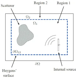
Fig. 1.TLM simulation domaincontaining scatterers and source elements. is subdivided in a total field region1and scattered
field region2. The dashed line indicates the Huygens’ surface
∂12.
In all simulations a perfectly matched layer (PML) bound-ary with 12 layers and a geometrical conductivity profile is used (Fichtner and Russer, 2009; Taflove, 2000). Conse-quently, the fields in region2can be used for the compu-tation of the radiated near-fields and far-fields as well as for the coupling of different TLM domains (Fichtner and Russer, 2009).
Using the TF/SF technique it is also possible to excite ar-bitrary wave forms within region1. These waves can ei-ther be analytically precomputed, e.g. for the excitation of arbitrary plane-waves (Taflove, 2000) or fields which origi-nate from other remote TLM domains (Lindenmeier et al., 1999; Fichtner and Russer, 2009). For the one-side excita-tion of incident waves, a modified TLM connecexcita-tion operator has been derived (Fichtner and Russer, 2009). WithkEincl,m,n andkHincl,m,nas the incident electric and magnetic fields, the modified TLM connection operator is written as
kal,m,n=ŴŴŴ·kbl,m,n (1)
+1 2
Ŵ
ŴŴE·kEincl,m,n+ŴŴŴH·kHincl,m,n
.
The connection matrices for the electric and the magnetic fields are
Ŵ ŴŴE=
A 0 0
0 A 0 0 0 A
, A=1l
1 −1 0 0 −1 1 0 0
0 0 1 −1
0 0 −1 1
(2)
and
ŴŴŴH=
B 0 0
0 B 0
0 0 B
, B=Z01l
1−1 0 0 1−1 0 0 0 0 −1 1 0 0 −1 1
. (3)
With Eqs. (1) to (3) it is possible to excite fields only within region 1. No fields in region 2 will be excited as required for the hybrid TD-IE/TLM method. For vanishing incident fields Eq. (1) reduces to the standard TLM connection operatorŴŴŴ
as required.
2.2 Coupling integrals
In numerical field computations the surface equivalence prin-ciple can be employed to compute the radiated electro-magnetic fields everywhere in space from the knowledge of the field distribution on an arbitrary closed surface ∂V, which encloses all source elements (Balanis, 1997; Taflove, 2000). Consequently, the radiated near-fields or far-fields can be computed for simulation domains of finite exten-sion (Taflove, 2000). The TD verexten-sion of the Stratton-Chu IE using exterior differential forms is given by
E(x,t )=µ∂ ∂t
Z
∂V′
I∧
nyn∧
H(x′,t′)
4π r
− Z
∂V′
⋆ R′∧I ∧E(x
′,t′)
4π r3 −
Z
∂V′
∂ ∂t′
⋆ R′∧I ∧E(x
′,t′)
4π r2c +
Z
∂V′
R∧⋆E(x
′,t′)
4π r3 +
Z
∂V′
∂ ∂t′R∧
⋆E(x′,t′)
4π r2c
(4)
whereIis the unit double-form I= dxdx′+dydy′+dzdz′
. (5)
(Details on exterior differential forms can be found in Russer (2006)). ByRandR′the distance 1-formR=(x−x′)dx+
(y−y′)dy+(z−z′)dz is denoted whereas primed or un-primed differentials are used respectively. The unit 1-form n in Eq. (4) is orthogonal to the considered plane of the Huy-gens’ surface and is oriented outwards. An expression for the radiated magnetic field analog to Eq. (4) follows from the principle of duality.
A time and space discrete version of Eq. (4) and its dual is obtained by expanding the fields into two-dimensional pulse-functions of edge length1land applying point-matching.1l
pact representation
kE(x)= 6 X
i=1 X
j h
LE E·k′E(xj) (6a)
+LE H·k′H(xj) i
,
kH(x)= 6 X
i=1 X
j h
LHE·k′E(xj) (6b)
+LHH·k′H(xj) i
.
The time index k′ is the retarded discrete time given by
k′=k−|x−xj|/c1twherexjis the source position andxis
the observation position. The operatorsLare computed from
Eq. (4) and consist of discrete temporal and spatial deriva-tives. From Eq. (6) the field at positionx is computed from
the retarded field values on a closed Huygens’ surface∂V
(see Fig. 1). In the hybrid TD-IE/TLM method the outgo-ing fields are probed on a closed Huygens’ surface which is located within region2. Using the probed fields as source terms, the radiated fields outside of the TLM domaincan be computed from Eq. (6). The radiated fields are used as ex-citation within a second TLM subdomain by using the TF/SF technique and the modified connection operator (1). Conse-quently, two or more TLM subdomains are electromagneti-cally coupled without discretizing the empty space between the subdomains.
3 The plane-wave time-domain algorithm
The dominant cost in the hybrid TD-IE/TLM method re-sults from the computation of Eq. (6) which scales with
O Ns2Nt. The number of basis-functions which constitute ∂12 is given byNs and Nt is the number of considered time-steps. A more efficient computation scheme is obtained if several source elements are first grouped together and in the following the contribution of every group is considered individually. This is basically done in the fast multipole method (FMM) used for the acceleration of frequency do-main (FD) moment method (MoM) implementations (Chew et al., 2001). A TD analog of the FMM, which uses a plane-wave expansion for the representation of the outgoing fields, has been developed by Ergin et al. (1999); Chew et al. (2001). The plane-wave time-domain (PWTD) algorithm employs a Whittaker-type field representation of the form
˜
ui(x,t )= − 1 8π c
∂
∂t
Z d
Z
V
dx′qi x′,t′
(7a)
=ui(x,t )− Z
V
dx′qi(x
′,t+r/c)
4π r (7b)
whereRdis the area integral over the unit sphere. The unit direction vector is given byk=exsinθcosφ+eysinθsinφ+
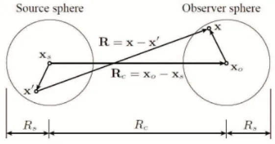
Fig. 2.Grouping of the source and observation positions inside two spheres of finite spatial extension.
ezcosθ andt′. The quantitiesu˜i(x,t ),ui(x,t )andqi(x,t ) are arbitrary field and source components respectively. In Eq. (7b) the second term on the right-hand side is anti-causal and can be eliminated by using proper time-gating techniques as outlined in Ergin et al. (1999); Chew et al. (2001).
Starting with Eq. (7) it is possible to derive a three-stage implementation for the summation in Eq. (6). According to Fig. 2 the distance vectorRbetween the source and
observa-tion posiobserva-tions is first rewritten as
R=x−x′=(x−xo)+Rc−(x′−xs) (8)
withRc=xo−xs. In the first stage of the PWTD algorithm
the source distribution is mapped onto outgoing plane-waves propagating in all directions. This operation is denoted as Slant-stack transform (SST) and is given by
qiout(k,t )= Z
V dx′qi
x′,t+k·(x
′−x
s) c
. (9)
In Eq. (9) the time-dependent source distributionqi(x′,t )is represented by outgoing rays in thek-th direction. In the
second stage the rays leaving the source sphere are translated onto the observation sphere via the convolution operation
qiin(k,t )=T(k,xc,t )∗qiout(k,t ) (10)
whereT(k,xc,t )is the diagonal translation operator
T(k,xc,t )= − 1 8π c
∂ ∂tδ
t−k·Rc
c
. (11)
The incident rays depend on the direction of arrival k and
timet. In the third and last step the incoming raysqiin(k,t )
are projected onto the observation positions using ˜
ui(x,t ) Z
dqiin
k,t−k·(x−xo)
c
. (12)
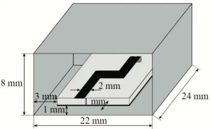
Fig. 3.Dimensions of the microstrip line inside the metallic enclo-sure.
applied. It can be shown that using the PWTD technique outlined between Eqs. (7) to (12) the computation of the TD-IEs scales with O Ns1.5NtlogNs. The acceleration is basically achieved by replacing the convolution in Eq. (10) with a multiplication whereas first the termsT(k,x′,t )and
qiout(k,t)are Fourier-transformed. After multiplication an inverse Fourier transform is applied. More details on the PWTD algorithm can be found in Ergin et al. (1999); Chew et al. (2001).
4 Simulation results
4.1 Shielding effectiveness (1)
The hybrid TD-IE/TLM method provides an efficient tool for the simulation and analysis of shielding problems. A mea-sure for the shielding performance of enclomea-sures and hous-ings is the shielding effectiveness (SE), defined as
SE=20·log10
E0
ES
, (13)
whereE0is the measured or simulated electric field with-out shield andES is the electric field when the shielding is used (Paul, 2006).
In a first test case a microstrip line with two 90◦ bends and a short at the end is placed inside a metallic enclosure. The microstrip line inside the metallic enclosure is shown in Fig. 3. The 90◦ bends of the line are not compensated us-ing mitered bends and hence spurious fields are excited at the bends. The microstrip line structure is excited using a waveguide port with a modulated Gaussian pulse defined be-tween the frequencies 5 and 20 GHz. From the short the main part of the incident wave is reflected and leaking out of the circuit.
Additional to the metallic box as shown in Fig. 3 a front panel will be used to reduce field leakage out of the enclo-sure. Two different configurations for the front panel are in-vestigated, which are shown in Fig. 4 (a) and (b). The front
(a)
(b)
Fig. 4.Different configurations for the front panel of the enclosure.
(a)exhibits a large air inlet of width 8 mm and height 4 mm. (b)
consits of several small air inlets.
panel in (a) exhibits a large air inlet of 8 mm width and 4 mm height and panel (b) has several smaller air inlets. Both air inlets (a) and (b) may serve as airflow apertures.
The electric field is measured 25 cm in front of the pan-els. In case of the TD-IE/TLM simulation the microstrip line and the enclosure is simulated with TLM whereas a Huy-gens’ surface close to the box is used to probe the electric and magnetic fields leaking out from the enclosure. These fields are used as sources in the TD-IE computation (6). The Huygens’ surface∂V is embedded within the source sphere as shown in Fig. 2. As the radiated fields at one position are required only, the first two steps of the PWTD algorithm are needed.
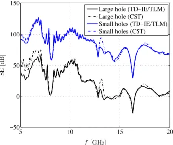
As a reference a CST simulation of the identical structure has been performed. The shielding effectiveness (SE) from 5 to 20 GHz for the two panel configurations are shown in Fig. 5. For panel configuration (a) SE values between 0 and 60 dB are achievable. At some frequencies, in particular at 16.5 GHz the SE is well below zero. In this case the air in-lets even enhance field leakage as they operate as aperture antennas (Paul, 2006). Using panel (b) the SE is about 50 dB higher in comparison to panel (a). The SE characteristic with respect to frequency of panel (b) is almost identical to panel (a) except for a positive 50 dB offset.
5 10 15 20 −50
0 50 100
f [GHz]
S
E
[d
B
]
Large hole (TD−IE/TLM) Large hole (CST) Small holes (TD−IE/TLM) Small holes (CST)
Fig. 5.TD-IE/TLM and CST computed shielding effectiveness (SE) for the two front panel configurations of Fig. 4.
4.2 Shielding effectiveness (2)
A further example concerning the shielding effectiveness is on the prevention of external radiation to penetrate into a metallic enclosure whereas different air inlet configurations are used. For this purpose a metallic box is considered which is irradiated by a broadband antenna. As antenna a planar bowtie will be used which can be modeled straightforward in TLM. The bowtie antenna geometry is shown in Fig. 6. For the excitation of the antenna an electric field oriented in
x-direction is impressed at its center. A modulated Gaussian pulse defined between the frequencies 1 and 5 GHz will be used for the excitation. Usually such investigations are per-formed in the far-field (Paul, 2006). As the limit between near-field and far-field, the Fraunhofer distanced=2D2/λ
is considered, whereD is the maximum overall antenna di-mension andλis the wavelength of interest (Balanis, 1997). For a frequency off =5 GHz and a maximum antenna di-mension ofD=95 mm, given from the bowtie diagonal, the Fraunhofer distanced is 300 mm. In order to have some ad-ditional space between box and antenna the separation is set toS=430 mm.
The complete simulation scenario is shown in Fig. 7. The TLM subdomain1 with the dimension 20×20×20 cells contains the planar bowtie antenna of Fig. 6. The metallic box is modeled within a second TLM subdomain′1of di-mension 41×41×31 cells. In both TLM subdomains the discretization1l=2.5 mm is used. The box has a square front with a side length of 105 mm and is 130 mm in depth. The two TLM subdomains in Fig. 7 show only the total-field regions. This means that the regions1 and′1are in ad-dition surrounded by a scattered-field domain2and′2 re-spectively, whereas each domain is four TLM cells in width.
Fig. 6.Geometry of planar bowtie antenna.
Fig. 7.TLM simulation scenario for the investigation of the shield-ing effectiveness of a metallic box irradiated by a planar bowtie antenna. The distance between the two TLM subdomain1and
′1isS=430 mm.
These scattered-field domains are not explicitly shown in Fig. 7. The TLM domains1and′1are embedded within the source and observation sphere respectively of the PWTD algorithm.
For the front plane of the metallic box four different con-figurations of air inlets are investigated. The front planes are shown in Fig. 8. For configuration (a) the inlets are square and have a width of 15 mm. The separation between the in-lets is 10 mm. In configuration (b) the width of the square inlets and the separation is identical to 5 mm. In case of con-figurations (c) and (d) the horizontal and vertical stripes have a width of 5 mm and a length of 65 mm.
(a) (b)
(c) (d)
Fig. 8.Air inlet configurations for the shielding effectiveness inves-tigations on the irradiated metallic enclosure.
are only weakly disturbed by the inlets. From the magni-tude spectrum in Fig. 9 it can be deduced that the highest shielding effect can be achieved if either the small inlets of configuration (b) or thex-directed slots of configuration (d) are used. In case of (b) the shielding is so strong that almost no resonances are excited within the box. The slots of config-uration (d) behave like a polarization filter and prevent most of the radiation from penetration into the box. The situation is different in case of configuration (c). Here the slots are oriented orthogonal to the polarization of the incoming elec-tric field and thus the fields can easily penetrate into the box. Though the formation of resonating modes is rather weak. It can be shown that the lowest order resonating modes are of TE10l-type with an electric field in x-direction. Due to the orientation of the metallic bars in case of configuration (c) the electric fields of the TE10l modes can easily leak out from the metallic box which explains the low quality factors.
5 Conclusion
A hybrid TD-IE/TLM method using the plane-wave time-domain technique has been presented for the fast and effi-cient modeling of typical shielding problems. Circuits to-gether with enclosures are modeling with TLM and the ra-diated fields in the near-as well as in the far-field are ob-tained from TD integral equations. The computational bur-den for the evaluation of the integral equations is lowered by using a suitable plane-wave representation. In case of the presented SE simulations the computational effort is lowered by a factor of 3 to 5 if the hybrid TD-IE/TLM method is used compared with a pure TLM simulation. Using the PWTD algorithm further 20% reduction in computational cost are achievable.
1 2 3 4 5
−50 0 50 100
f [GHz]
|
E
x |
[d
B
]
Large squares Small squares y−slots x−slots
Fig. 9.Magnitude spectrum of theExfield components measured inside a metallic box for the different front panel configurations of Fig. 8.
Acknowledgements. This work was supported by the Deutsche Forschungsgemeinschaft (DFG).
References
Balanis, C.: Antenna Theory – Analysis and Design, John Wiley & Sons, 2nd edn., 1997.
Chew, W., Michielssen, E., Song, J. M., and Jin, J. M.: Fast and Efficient Algorithms in Computational Electromagnetics, Artech House, Norwood, MA, USA, 2001.
Ergin, A., Shanker, B., and Michielssen, E.: The Plane-Wave Time Domain Algorithm for the Fast Analysis of Transient Wave Phe-nomena, IEEE Trans. Antennas Propagat. Magazine, 41, 39–52, 1999.
Fichtner, N. and Russer, P.: A Total-Field/Scattered-Field Tech-nique Applied for the TLM-Integral Equation Method, 2009 IEEE MTT-S Int. Microwave Symp. Dig, 325–328, 2009. Hansen, T. and Yaghjian, A.: Plane-Wave Theory of Time-Domain
Fields, IEEE Press, 1999.
Lindenmeier, S., Pierantoni, L., and Russer, R.: Hybrid Space Dis-cretization – Integral Equation Methods for Numerical Modeling of Transient Interference, 1999, IEEE Trans. Electromagn. Com-patibility, 41, 425–430, 1999.
Paul, C.: Introduction to Electromagnetic Compatibility, Wiley Se-ries in Microwave and Optical Engineering, John Wiley & Sons, New York, 2nd edn., 2006.
Russer, P.: Electromagnetics, Microwave Circuit and Antenna De-sign for Communication Engineering, Artech House, 2nd edn., 2006.
Taflove, A.: Computational Electrodynamics – The Finite Differ-ence Time-Domain Method, Artech House, Boston, 2nd edn., 2000.