POSE ESTIMATION OF A HUMANOID ROBOT USING IMAGES FROM A MOBILE EXTERNAL
CAMERA
Marcelo Borges Nogueira∗
Adelardo A. D. Medeiros∗ Pablo J. Alsina∗
∗Universidade Federal do Rio Grande do Norte
Departamento de Engenharia de Computa¸c˜ao e Automa¸cao UFRN-CT-DCA – Campus Universit´ario – 59072-970
Natal-RN Brazil
Abstract: This paper describes an ongoing project to move a simple humanoid robot, without an advanced embedded electronics. We used another wheeled mobile robot which already has a locating system and is equipped with a camera. We will locate the humanoid in the environment based on images, and then take the necessary actions to move it. In the future, we will also move the robot with the camera, so it will take good images of the humanoid.
Keywords: multi-robot cooperation, relative positioning, humanoid, pose estimation
1. INTRODUCTION
One of the main task of a mobile robot navigation system is to determine the robots position and orientation in its work environment.
Some of the most utilized locating sensor are en-coders, sonars, cameras, compass and laser range-finders. One of the most popular and cheap is odometry. However, is is not a simple task to use odometry with legged robots, since they do not have a fixed length step. Besides, the sliding is usually a lot bigger than with wheeled robots. That is why locating humanoid robots suggests other methods. Some of these methods are very expensive (laser range-finder and GPS) and oth-ers give us sparse information (sonar)(Albert and Connell, 2004). Hence, a visual navigation system becomes attractive due to its low cost and the high processing power of current computers.
One possibility would be to equip the humanoid with one or more cameras. However this would lead to a big humanoid or to an expensive
em-bedded electronics. Besides, the locating system (hence also the camera) would have to be very accurate, since this would be the only method to locate the robot on the environment.
To build or acquire a big humanoid (adult size) is a difficult, long and expensive task. For this reason, we chose to work with a small humanoid robot, remote controlled and without an advanced em-bedded electronics. The humanoid robot acquired was the Robosapien (Wee, 2004), shown if Figure 1, fromWow Wee. Therefore, we chose a strategy that combines odometry and vision.
commands to the humanoid robot via infra-red. The project is in a initial phase, and will study camera calibration techniques and the humanoid movements.
Fig. 1. The Robosapien humanoid robot
We suppose that the wheeled robot (which we will call camera from now on) already have a locating system and knows how to navigate in its work environment (given the current position, the camera knows which actions to take so to reach the target position). This way, knowing the position of the humanoid relative to the camera and supposing the position of the camera in the world is known, we can calculate the position of the humanoid robot in the world. This makes possible for us to control the humanoid. To do so, we will use a heuristic technique detailed in Section 5.
The main goal is to correctly move the humanoid around the environment. However, is is also nec-essary to move the camera, so it will follow the humanoid through the work environment and take good images of him. The technique used to move the camera will be discussed in Section 6.
Fig. 2. Proposed system: humanoid robot ob-served by external mobile camera
To obtain spatial (3D) information from a 2D im-age it is necessary a camera calibration. In Section 2 this process will be detailed. Experiments, re-sults and conclusions will be presented in Sections 7 and 8 respectively.
2. CAMERA CALIBRATION
Camera calibration is to calculate a set of values relative to the camera that makes possible to interpret images acquired by this camera. It can be divided in two steps: calculating its interior ori-entation parameters, or intrinsic calibration, and calculating it’s exterior orientation parameters, or extrinsic calibration.
The intrinsic calibration is an off-line procedure, that is, it is made before the control system of the robot is working. Besides, it needs to be done just once, since the interior parameters of a camera (usually) do not change over time. Hence, time constraints are not critical in this calibration phase. On the other hand, the extrinsic calibration phase has a serious time restriction, since it must run at each control sampling time.
Suppose {R} the world’s 3D coordinate system, in centimeters, {C} the camera’s 3D coordinate system, in centimeters,{I} the image’s 2D coor-dinate system, in centimeters and{F}the image’s 2D coordinate system, in pixels. Using the pinhole camera model we can find: (Zhang, 2000):
C
z F
P 1
=A·CTR· R
P 1T
(1)
where F
P = [F
x F
y]T
is a point relative to{F},
R
P= [R
xRy Rz]T is a point relative to{
R},C
zis the z coordinate of a point relative to{C},C
TRis
the transformation matrix between{C}and{R} andAis the intrinsic parameters matrix, given by:
A=
α γ F
x0
0 β F
y0 0 0 1
(2)
where (F
x0,F
y0) are the image center coordinates, in pixels,αandβ are respectively ratios between the scale factors in the images axes xand y and the focal distance of the camera and γ is the distortion of the angle formed by the axes.
2.1 Intrinsic Camera Calibration
Intrinsic camera calibration means finding the intrinsic properties of the camera (matrixAshow in equation 2). There are several methods in the literature about intrinsic camera calibration. An analysis of these methods is made by Nogueira (Nogueira, 2005).
can or can not be coplanar, depending on the method. After an analysis, we decided that the method that best suits the proposed system is the one proposed by Zhang (Zhang, 2000) due to his flexibility, robustness and low computational cost.
In this method, it is necessary that the camera observes a flat pattern of known measures from at least two different positions. However, it is not needed that we know the displacement made by the camera between the observations. The coordinate system of the pattern must be chosen so that thezcoordinate of each point on the patter will be zero. An example of such a pattern can be observed in Figure 6. Based on these information, after finding the target points on the pattern (the method we used to do this will be discussed in Section 3), the Zhang method will gives us an initial guess of the intrinsic parameters matrix. This initial guess has an error, due to non-linear distortions caused by the lenses.
From this initial guess, we can conduct a linear optimization so to reduce the error between the observed points and the ones calculated by the Equation 1.
2.2 Extrinsic Camera Calibration
The extrinsic parameters are the position and orientation of the camera relative to the world’s system coordinate (matrix C
TR in Equation 1).
For this reason, this phase is also called pose estimation.
There are several different ways to solve this problem (Nogueira, 2005). In this paper we will discuss the so called PnP, or Perspective-n-Point methods, which consist in calculating the pose of an object using ntargets points belonging to the object and that appear in an image of this object.
To solve the PnP problem we need at least 3 target points. However, in this case, there will be multiple solutions (as much as 8), what demands a further processing to choose one of these solutions (Haralick et al., 1991). To find only one solution we need at least 4 target points. According to the way it is solved, the P4P can be classified in: solution by optimization and analytic solution. Among the existing P4P methods, we chose the one proposed by Kamata et al (Kamata et al., 1992).
The P4P (Perspective Four-Points problem) method proposed by Kamata has the advantage of having a analytic solution. This is a very important fea-ture, due to the time restriction in this phase.
Kamata’s method consists of, from four coplanar points known relative to {R}: R
P0 to R
P3, and
the corresponding 2D image points F
P0 to F
P3
(the method to detect these points in the image will be shown in Section 4), calculate the matrix
C
TR, introducing some intermediate coordinate
systems.
3. EXTRACTING THE TARGET POINTS FOR THE INTRINSIC CALIBRATION
To use Zhang’s method, we must detect at least 6 points in the image. However, to minimize the error, it is advisable to use more points.
To improve system precision, instead of directly detecting those points, we will look for straight lines, which intersections will give us the needed points. To calculate the straight lines we used the classical Hough algorithm.
The Hough transform is a method to detect a class of geometric known forms, which can be repre-sented as a parametric curve, (like straight lines, polynomials, circles, etc.), in an image (Hough, 1962). It has a high computational cost, but this is not a problem, since this phase does not demand a real time algorithm.
Figure 6 shows the pattern we used: a set of 18 straight lines giving a total of 81 points.
4. EXTRACTING THE TARGET POINTS FOR THE EXTRINSIC CALIBRATION
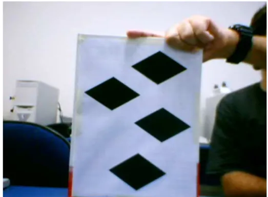
We will use the same strategy we used to extract the target points for the intrinsic calibration, that is, we will use lines which intersection will give us the points. Since the P4P method needs 4 points, we will use a quadrilateral mark (in this case, a rhombus), which was placed on the humanoid robot, as shown in Figure 7. The intersection of its edges will give us its vertices. We could have used the Hough algorithm once again to calculate the rhombus edges, but this phase is executed at each sampling time and requires a faster response. Therefore, we developed a faster method to extract the vertices of a rhombus.
4.1 Detecting Rhombus Vertices
Table 1. Detecting points that belongs to the rhombus edges
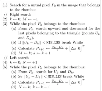
(1) Search for a initial pixelP0in the image that belongs
to the rhombus // Right search (2) k←0;M← −1
(3) While the pixelPkbelongs to the rhombus:
(a) FromPk, search upward and downward for the
last pixels belonging to the triangle (pointsUk
andDk).
(b) IfkUk−Dkk<MIN_LENbreak While
(c) CalculatePk+1← Uk−Dk
2 +
∆x 0T (d) M←k;k←k+ 1
// Left search (4) k←0;N←+1
(5) While the pixelPkbelongs to the rhombus:
(a) FromPk, search forUkandDk.
(b) SekUk−Dkk<MIN_LENbreak While
(c) CalculatePk−1← Uk−Dk
2 −
∆x 0T (d) N←k;k←k−1
This way, initially, starting from a point belonging to the rhombus (P0) we find a set of points belonging to its edges (Ui eDi). This process is
presented in Table 1 and illustrated in Figure 3.
We calculate then two straight lines for the Ui
points:LU
L, which goes from the left to the center;
andLU
R, which goes from the right to the center.
Similarly, we calculate the straight lines LD L and
LD
R from the Di points. Such straight lines are
calculated so to minimize the quadratic error to the set of points associated with each one of them. The way each point is associated to a straight line is described in Table 2. Once we have the straight lines, their intersection will give us the four points needed.
P0
D0 D 1
D
−N D
−1 P
−1 P
−N
U0 U1
U −1
U −N
∆x
DM
UM
PM
P1
Fig. 3. Detecting points that belongs to the rhom-bus edges
5. HUMANOID MOVEMENTS
The humanoid is controlled by infra-red, and has the following motion commands: walk forward, walk backward, turn left and turn right. It has a static walk, that is, its center of gravity always remains at the middle of the foot of the robot.
Due to movement restriction and the difficulty to precisely control the position of the humanoid, we decided to use a heuristic control technique.
Table 2. Detecting lines of rhombus edges
// Up
(1) InitializeLU
Lwith the coefficients determined by the
points U−N and U−(N−1) and LUR, with UM and UM−1.
(2) i← −(N−2) (3) Whilei≤M−2:
(a) Calculate the distanceseU Lande
U
R, the distances
between the pointUi andLUL andL U R,
respec-tively. (b) IfeU
L < e U
R, recalculate the coefficients ofL U L,
consideringUibelongs to it; else, recalculate the
coefficients ofLU R.
(c) i←i+ 1 // Down
(4) Do a similar procedure (steps 1 to 3) to determine
LD L andL
D
R from theDipoints.
The first step is to calculate a trajectory, given the initial point PI and a final point PF of the
humanoid.
The control steps will be: First, calculate the error e between the humanoid position and the desired robot position and the angle α between the vector from the robot toPF and the zaxis of
the humanoid (zR) (Figure 4). Ifαis greater than
a certain valuek, we command the robot to turn so to make α close to zero. Next, if e is greater than a certain valuel, the robot is commanded to walk forward.
PF
zR
α e
Fig. 4. Humanoid movements
6. CAMERA MOVEMENTS
The camera movements are totally dependent of the humanoid movements, because the camera has to follow the humanoid so it will take good pictures of the mark attached to the humanoid. To do this, we have to command the camera to a position that is distant d from the humanoid and from where the camera aims at the humanoid (the center of the rhombus is at the center of the image). If the x axis of the humanoid (xR)
reaches a critical angle θ with the z axis of the camera (zC) (Figure 5), what would not give a
to the positionPD in Figure 5, which is distantd
from the humanoid and in a way that θ is 90o
. This leads to a non-continuous movements, but if the generated trajectory is sufficient smooth, this will not happen frequently.
A especial case that should be observed is when the desired camera position causes a collision with some object. In this case, we must sacrifice temporarily the visibility of the humanoid and place the camera closest to its desired position without causing a collision.
θ
PF
PD
d
xR
zC
PI
Fig. 5. Critical angle situation
7. EXPERIMENTS AND RESULTS
Lets analyze first the camera calibration process. Figure 6 shows the Hough algorithm applied on a pattern to detect the target points needed to cali-brate the intrinsic parameters of a camera. Figure 7 shows the result of the developed method to detect rhombus vertices to calibrate the extrinsic parameters of a camera.
Fig. 6. Extracting target points for intrinsic cam-era calibration
In the intrinsic camera calibration using 4 differ-ent images of the pattern shown in figure 6, we found the following intrinsic parameters matrixA:
A=
757,25 2,06 389,67 0 754,24 260,5
0 0 1
(3)
To validate the intrinsic parameters found and, at the same time, the extrinsic calibration process,
Fig. 7. Extracting target points for extrinsic cam-era calibration
we used the calculated matrix A to find the po-sition of the camera using 4 rhombuses showed in Figure 8 which position are known relative to the world. The result for each rhombus should be all the same. The result for each rhombus (in centimeters and degrees) and the mean error be-tween the observations (in centimeters) are shown in Table 3. Notice that the errors in thexand y axes and Roll and Yaw angle are small. The errors in thezaxe and in the Pitch angle are higher, but still acceptable given the nature of the problem.
Fig. 8. Rhombuses used for validating intrinsic and extrinsic calibration
Rho. 1 Rho. 2 Rho 3 Rho. 4 Error
x -9,808 -9,838 -10,308 -9,93 0,265
y 18,059 17,428 17,235 16,962 0,580
z 36,87 38,114 37,532 39,515 1,419 Roll -1,682 3,583 -1,433 -1,5 2,643 Pitch -5,253 -2,782 7,878 -4,524 6,855 Yaw 0,91 2,536 2,261 2,525 0,857
Table 3. Calibration results for figure 8
To analyze the humanoid heuristic control method we commanded it to a final position (x, y, z) = (0,4.7,60) from the start position (0,4.7,29) and
Pitch=0. The z axis position of the humanoid
during the experiment can be seen in figure 9. The final position achieved by the humanoid was (3.3,4.8,58.2). In this experiment, the wheeled robot did not move, since this functionality will be implemented later.
Fig. 9.z position of the humanoid relative to the world
This tell us that the camera should be as close as possible to the humanoid so to fit the rhombus image with its vertex reaching the boundaries of the whole image. However, if the camera is too close, one or more vertices of the rhombus can be momentarily out of the image. Besides, the camera should keep a certain distance from the humanoid so it can freely move in the environment. There-fore, we have to calculate the optimal distance d that the camera should keep from the humanoid.
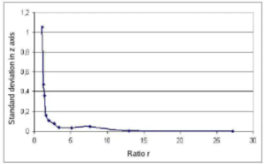
Figure 10 shows the standard deviation between several estimations of thezposition of the camera in function ofr, which is the ratio between rhom-bus area and total figure area. Notice that whenr is bigger than 5%, the deviation varies just a litte, but whenrbecomes smaller than 5% the deviation increases rapidly. This show us that we should
keep r less than 5% so the measurements are
coherent. This ratio corresponds to the distance
d= 25cm.
To determine the critical angle we did a similar process used to calculate the distanced. Position-ing the camera 25cm from the humanoid and cal-culating the standard deviation for several mea-sures (pose estimation) against several different pitch angles, we can determine the critical angelθ which keeps the standard deviation less than 5%, which we found to be 50 degrees.
Fig. 10. Standard deviation in humanoid esti-matedzposition againstr
8. CONCLUSIONS
Zhang’s intrinsic calibration method showed to be appropriate to the system, giving a flexible, fast
and robust calibration. The Hough algorithm was very precise detecting the straight lines
Since it has a analytic solution, the P4P proposed by Kamata gives us a constant time response, ideal for real time applications. The proposed method to extract the vertices of the rhombus showed to be very fast and robust, even with low cost web cameras and illumination variation.
The heuristic method to control the humanoid was appropriate to its limited kind of motion, and we made an analysis of the position that the camera should stay to minimize the error in the pose estimation process.
The presented system can be used in applications where, besides a humanoid robot, is also available a second mobile robot with a precise locating sys-tem and a camera. It allows experiments with low cost and simple embedded electronics humanoid robots.
REFERENCES
Albert, M. E. and J.H. Connell (2004). Visual rotation detection and estimation for mo-bile robot navigation. In:IEEE International Conference on Robotics and Automation. Faugeras, O. D., Q.-T. Luong and S.J.
May-bank (1992). Camera self-calibration: Theory and experiments. In:European Conference on Computer Vision. pp. 321–334.
Haralick, Robert M., Chung-Nan Lee, Karsten Ottenberg and Michael N¨olle (1991). Analysis and solutions of the three point perspective
pose estimation problem. In: CVPR - IEEE
Conference on Computer Vision and Pattern Recognition. Maui, HA, USA.
Hough, P. V. C. (1962). Methods and means for recognizing complex patterns.
Kamata, Sei-ichiro, Richard O. Eason, Masafumi Tsuji and Eiji Kawaguchi (1992). A camera calibration using 4 point-targets. In: 11th IAPR - International Conference on Pattern Recognition. Hague, Netherlands.
Longuet-Higgins, H., C (1981). A computer algo-rithm for reconstructing a scene from two pro-jections.Naturepp. 133–135.
Nogueira, Marcelo B. (2005). Posicionamento e movimenta¸c˜ao de um robˆo human´oide uti-lizando imagens de uma cˆamera m´ovel ex-terna. Master’s thesis. UFRN, Natal- RN. Wee, Wow (2004). www.robosapienonline.com. Zhang, Z (2000). A flexible new technique for
camera calibration. IEEE Transactions on