Scenario-Based Software Reliability Testing Profile
for Autonomous Control System
Jun Ai
School of Reliability and System Engineering
Beihang University Beijing, China
Jingwei Shang School of Reliability and System
Engineering Beihang University
Beijing, China
Peng Wang
School of Reliability and System Engineering
Beihang University Beijing, China
Abstract—Operational profile is often used in software reliability testing, but it is limited to non-obvious-operation software such as Autonomous Control System. After analyzing the autonomous control system and scenario technology, a scenario-based profile constructing method for software reliability testing is presented. Two levels of scenario-based profile in the paper are introduced: system level and software level, and the scenario-based profile could be obtained through mapping them. With the method, the testing data for software reliability testing could be generated.
Keywords- software reliability testing; scenario-based testing profile; autonomous control system.
I. INTRODUCTION
Software Reliability Testing(SRT) is used to ensure and verify software reliability requirement. The regular method is to perform a random statistical testing which is based on operational profile [1][2][3]. Operation profile delegates the probability distribution of the software usage, and the testing data could be generated by random sample with it[4][5][6]. But operational profile is limited to the Autonomous control system(ACS), in which the operation is not obvious.
Autonomous control system (ACS) usually has autonomy as it could run without people. The missile and unmanned plane are two typical examples [10]. It is a kind of non-obvious-operation system. The traditional operational profile could not be used in ACS directly. Consequently, it is necessary to develop a profile constructing method for ACS.
This paper describes a scenario-based software reliability testing profile (SRTP), which could solve the problem mentioned above about ACS. At first, the feature of ACS and the limitation of operational profile in SRT for ACS are analyzed. And then the conception and constructing method of scenario-based SRTP are presented combing with scenario technique. Finally, the feasibility would be validated by an instance.
II. SRTP REQUIREMENTS OF ACS
ACS does not have obvious operations. The running process of ACS is affected by system interactive, environment influencing and activity sequential. Therefore, there are some new technical requirements for the SRTP of ACS.
A. System-interactive:
System-interactive means the running of ACS software is affected by the cross-linking systems of ACS. At every moment, the stimulated inputs from the other cross-linking systems happen synchronously.
Different system interactions may cause different running modes and the states of the software are possibly determined by all inputs from the cross-linking systems. Consequently, all of the possible systems and their running processes should be presented in the SRTP.
B. Evironment-influencing:
Environment-influencing means ACS is sensitive to the change of environment. In other words, different strategies would be made along with the change by ACS. Autonomy control means online perceiving situation, making strategies and executing missions automatically according to definite assignments and principles [9]. Accordingly, to truly simulate software running processes, external environment in the life cycle of ACS should be described in testing profile.
C. Active-sequential:
Active-sequential means the system running periods could be apperceived by ACS in entire lifecycle, and all of the actives are sequentially. While working, real-time mission evaluation should be made, the mission in which period and the accomplishments should be determined by ACS. In addition, the next activity should be decided automatically too. Consequently, testing profile should be able to describe the mission periods and their time sequence.
According to these characteristics and SRT technical requirements of ACS, this paper proposes a testing profile constructing method based on scenario to support SRT for this kind of system.
III. SCENARIO-BASED SRTP
At first, the concept of usage scenario for software is made as follow:
Therefore, for the software of ACS, the usage scenario and its corresponding probability constitute its scenario-based SRTP. And the scenario-based SRTP can be express as:
SP={<Sys, So>} (1)
Sys={Sc1, Sc2, Sc3,…,Sci,…,Scn} (2)
Sc={<Pi, Fj>;i=1,2,3,…,m; j=1,2,3,…,n } (3)
P={<Ti, pi>,i=1,2,3,…,n} (4)
So={< Ai, pi, Lj,>} (5)
A={<Ii,Oi, pi>} (6) In the formulas,SP refers to the scenario-based SRTP; Sys
refers to the system under test(SUT); So refers to the software under test; Sc refers to cross-linking system; P refers to parameter of the interactive system; F refers to function of the interactive system; T refers to equivalence class; A refers to activity; L refers to layer of the activity; I is a input of the activity; O refers to output of the activity; p refers to the corresponding probability.
As mentioned above, a complete usage scenario profile should include descriptions of both the system’s and software’s running process and their statistical distribution. The constitution of usage scenario profile is shown in Figure 1. :
Usage Scenario
System Scenario
Software Scenario
System Process
Associate Systems
Software Activities
Data Scenario Mapping
Figure 1. Constitution of usage scenario profile
In other words, the usage scenario profile consists of system scenario profile and software scenario profile. System scenario profile is used to describe the running process of ACS and its statistical distribution, including system running states, environments, and external driving sources. Software scenario profile is used to describe software running states and possible inputs and their distribution. System scenario profile is looked as the constraints of software scenario, which define the possible running condition of the software; while software scenario is the detail representation of system scenario. The combination of the two scenario profiles performs an expression of the software usage.
IV. SCENARIO-BASED SRTP CONSTRUCTION According to the analysis of scenario-based SRTP, the main constructing process can be shown in Figure 2. .
System Scenario Software Scenario
Mapping
Profile Construction Testing Data Limitetion
Manifestations
Property/Function
Software Activities
Software Info
Independent Scenario Information
Model Tranceformation Scenario Construction
Figure 2. The constructing process of scenario-based SRTP
At first, the usage scenario should be analyzed and modeled in system level and software level. In this way, the system scenario profile and software scenario profile could be constructed. And then the mapping from system scenarios to software scenarios according to their properties would be made. In this step, independent system scenario should be extracted from the system scenario profile, which would be used to analyze software scenario profile. After the analysis, the input and output during the software process could be obtained, and the corresponding SRT data could be generated.
During the constructing process, some UML standard diagrams could be used to describe the usage scenario profile. The details are introduced as follows:
A. System Scenario profile Construction
Scenario-based SRTP includes description of the software under test and associate systems during the software process. As a top-to-bottom constructing method, analysis and construction of the associate systems should be done firstly. The main purpose of system scenario profile construction is describing system’s states and environments during the system’s running process and all the factors which could affect the running of system.
Commonly, there are four steps in the system scenario profile construction:
1) Define associate systems: including the SUT, associate system, user, and enviroment;
2) Define external interactions of the systems: including the interactions between SUT and other systems; 3) Define the running input data: including the input data
lead to the change of the state of SUT;
4) Define the factors and their distribution: including all the factors which could affect the running of system and the occurrence probability of the factors.
Data A is twice of Data B. An example of system and its interactions is expressed as Figure 3.
+OperationA() User -DataA
+OperationA() +OperationX()
System Under Test -DataA
-DataX -Data1
+OperationX() Associate System -DataX
Enviroment -Data1 *
* * *
* * *
*
Figure 3. System and its interactions
In the system scenario, activities of users, interactions of cross-linking systems, effect of environment, and other influence from the SUT should be described. The factors which could affect the running of system should be listed and possible value range or value trend of the factors should be given. The factors and its value distribution could be expressed with a system scenario profile table, such as TABLEI.
TABLE I. EXAMPLE OF FACTOR TABLE
Factor Value range
Probability Source Target ….
Altitude 1~100 0.3 Altitude
meter
System …
100~1000 0.7 Altitude
meter
System …
Speed <20km/h 0.4 Speed
meter
System
… … … … …
B. Software Scenario Profile Construction
The main purpose of this period is to construct the scenario model of software running process and its input infomation.
1) Activity dividing: dividing task of the software according to the main purpose of each activity.
2) Use case modeling: constructing functional use case models for the software according to the mission and process.
ActorA
Usecase1
Usecase2 Package
ActorX *
*
*
*
* *
* * *
* *
*
Figure 4. Use case model example of software function
As shown in Figure 4. , use case model (which is expressed by Use case Diagram) is used to analyze functional requirements of the software. However, the detailed description for each function is not necessary.
3) Scenario flow analyzing: software scenario can be determined by a path through use cases. A path starts from a use case and ends with a use case, traversaling through all of the basic-flow and alternative-flow.
State 1 State 2
/ Basic flow / Basic flow / Basic flow / Alternative flow
Figure 5. Software scenario flow example
As shown in Figure 5. , software scenario flow could be expressed by State chart Diagram. Each path describes a basic-flow or an alternative-basic-flow with an arrow-line.
Basic-flow: an arrow-line which is the simplest path through the regular use cases; in this path the program should run from beginning to the end with no error.
Alternative-flow: an arrow-line which starts from a basic-flow or an alternative-basic-flow in some specific conditions, and rejoin the basic-flow or ends with a use case.
Combining the basic-flow and alternative-flows, a scenario table can be obtained, such as TABLE II.
TABLE II. SOFTWARESCENARIOFLOW
S 1 BF
S 2 BF AF 1
… … … …
S 8 BF AF 3 AF 4
4) Scenario flow Refine: analyzing the basic-flow and alternative-flows according to the stimulation and sources, the equivalence class of inputs could be divided.
UserA System SystemX
M1
M2 M3
M4
Figure 6. Software scenario flow refine example
It could be expressed by Sequence Diagram, as shown in Figure 6. The arrow-line in the diagram presents messages and data in the interactions.
5) Scenario Splicing: A software scenario with inputs and output could be obtained by splicing sequence diagrams in the “scenario flow refine” process according to the orders in the basic-flow or alternative-flow.
defines the relevant data and covers the use case flows through the path. Data associates with specific scenarios by means of input/output and some intermediate state. There would be multiple use cases in a complex scenario. The operations between use cases are described by execution orders, controlling conditions, parallels, or loops.
C. Scenario Mapping
System scenario and software scenario describe the running process of the software under test in macro and micro view. Using them without connections could not satisfy the testing requirements mentioned before.
Decision table could be used to map system scenarios with software scenarios. A decision table example is shown in TABLE III. , where each row represents software scenario and each column represent a system scenario. Each software scenario should contain the scenario ID, conditions (or states), all data and the expected results elements involved. The decision table should at least include necessary system scenario information in executing a software scenario.
TABLE III. SCENARIOMAPPINGDECISIONTABLEEXAMPLE
S ID S Data X1 Data Y1 Active A1 Result
S1. BF V V V A1
S2. BF-AF2 V V V Active1-
Active2
S3. BF-AF I V n/a
Active1-
Active3-
Active1
Here V means the basic-flow could be executed only when the condition is valid; the I means in the invalid condition the alternative-flow would be activated; and n/a means the condition is not applicable to this scenario.
By scenario mapping, the activities in software scenario could be Modular with details, and a scenario combing system scenario with software scenario could be obtained, which could be used to generate software reliability testing data.
D. Distributing probability
By distributing probabilities to each data, activity, and branches in the scenario diagrams and tables, a scenario profile with both scenarios and probabilities is produced.
Then we could obtain software reliability test cases by extracting a certain scenario and necessary data in describing scenario from the profile.
Therefore, scenario-based SRTP construction is an iterative process of refinement. Describe system and software behaviors in different points of view.
V. INSTANCE VALIDATION
An ACS software has been taken as an instance, which is a flight control system for a model airplane. In the issue, we simplified the detail data of the system. The scenario-based SRTP is constructed as follow:
A. System Scenario Profile Constructing
By analyzing the embedded ACS, the system scenario contains the system under test, seeker, fuse, environment and the carrier aircraft.
+Send Task() +Guidance Revise() -Task Info -Guidance Info
Carrier
+Seeker Control() +Fuse control() +Guidance revise() -Seeker Signal -Fuse Signal -Guidance data
SUT
+Guide() -Guidance Data
Seeker
+Detonate() -Fuse Signal
Fuse -Distance
-Hight Enviroment *
* * *
* *
*
* *
* * *
Figure 7. ACS system scenario construction diagram
We analyzing the input/output and activity of each object, and construct a system scenario as Figure 7, and the factor table is as TABLE I. ACS system scenario contains description of both objects and their factors.
B. Software Scenario Profile Construction
Construct the functional use case model as Figure 8. :
Carrier
Guidance recise
Seeker Control Con-Flight
Enviroment *
* *
* *
* *
*
Fuse Control System Under Test
Seeker
Fuse *
*
* * *
*
* *
Figure 8. ACS functional use case diagram
A complex use case sequence contains guidance revise, seeker control, and fuse control is selected as an example for scenario flow analyzing, as in Figure 9. :
Guidance Revise
Send Fuse Control Signal Target
Intercepted
Fuse Control
Whether be in Fuse
Working Distance
Figure 9. ACS scenario flow diagram
TABLE IV. SIMPLIFYACSSCENARIOFLOWTABLE
S 1 Guidance Revise
S 2 Guidance Revise Seeker Control Target Lost
… … … …
The refined scenario flow sequence diagram will be express in the following process.
C. Scenario Mapping
Decision table based for scenario mapping can be demonstrated as TABLE V. :
TABLE V. SIMPLIFYACSSCENARIOMAPPINGDECISION TABLE
S ID Guidance Revise
Data
Seeker Working Distance
Fuse Working Distance
Fuse Result
S1. V I n/a n/a Guidance
Flight
… … … …
S4. V Seeker
Control
Fuse
Control
S 4 Guidance Revise
D. Scenario Profile and Test Data
By distributing probabilities to each data, activity, and branches in the scenario, the scenario profile with scenarios and probabilities is generated. Then a scenario such as figure 12 could be extracted.
Enviroment ACS Seeker
Guidance
Guidance Signal Seeker Signal
Seeker Control
Fuse
Guidance Revise
Seeker Signal
Figure 10. scenario sequence diagram
According to the system scenario factors in the scenario mapping table, the properties of system scenario are determined. By make a secant ling through the ACS scenario sequence diagram, data across the secant line is the test data in the very scenario.
A scenario-based SRTP constructing process for the ACS is demonstrated above. In particular, some data are simplified in the process.
VI. SUMMARY
A scenario-based SRTP constructing method is proposed in this paper. With system scenario profile and software scenario
profile, the possible running state and usage of the SUT could be modeled.
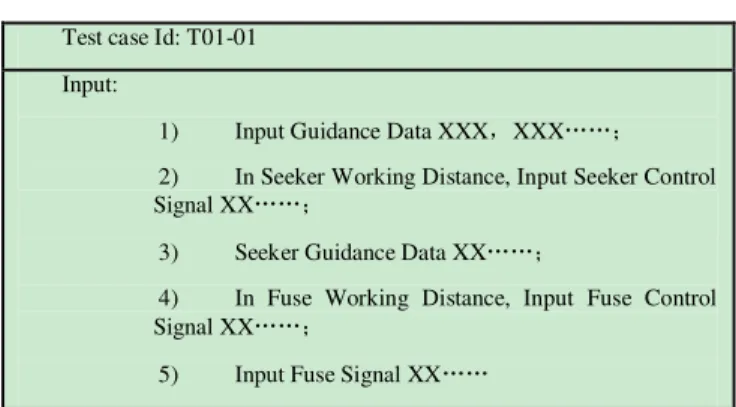
TABLE VI. SIMPLIFYTESTCASE
Test case Id: T01-01
Input:
1) Input Guidance Data XXX,XXX……;
2) In Seeker Working Distance, Input Seeker Control Signal XX……;
3) Seeker Guidance Data XX……;
4) In Fuse Working Distance, Input Fuse Control Signal XX……;
5) Input Fuse Signal XX……
According to scenario profile, the software reliability test case could be generated. The problem that traditional operation profile could not be used in ACS has been resolved. With the instance of a flight control system for model airplane, the method in this paper is effective.
REFERENCES
[1] Lu Minyan, Chen Xuesong,”Software Reliability Testing and Practice”.Testing and Control Technology, vol. 19, 2000,pp. 509-512. [2] Musa J D.”Operational profiles in software reliability engineering”.
IEEE Software , vol.10(2) ,1993, pp.14-32
[3] Ai, Jun ,Lu, Min-Yan, “The analysis and modeling for the input space of real-time embedded software”, 8th International Conference on Reliability, Maintainability and Safety, 2009, pp. 774 - 777
[4] Elbaum, S.; Narla, S.” A methodology for operational profile
refinement”, Reliability and Maintainability Symposium ,2001, pp. 142 - 149
[5] Saravana Kumar. K., Misra. R.B.and Goyal, N.K., "Development of Fuzzy Software Operational Profile",Secure System Integration and Reliability Improvement,Second International Conference on 2008, pp.195 – 196
[6] Gittens, M.,Lutfiyya, H.and Bauer, M."An extended operational profile model",15th International Symposium on Software Reliability Engineering, 2004, pp.314 - 325.
[7] Xiaofeng L,Chenggang B and Liang S,"Software Operational Profile Modeling and Reliability Prediction with an Open Environment ",10th International Conference on Quality Software (QSIC), 2010,pp.227 - 231
[8] Urem, Frane, Mikulic and Zelimir," Developing operational profile for ERP software module reliability prediction ",2010 Proceedings of the 33rd International Convention , pp. 409 - 413.
[9] Huang Yongfei, Peng Xinjie, “Missle Flight Control System Testing” , Missle and Guidance,Vol.29,2009, pp. 65-67.
[10] Ma Sasa,Chen Zili, Li Bing “UAV Flight Control Software Testing Technique “, Radio Engineering,Vol.34(10),2004. pp. 53-57
AUTHORS PROFILE
Jun Ai is the deputy director of Center of Software Dependability in School of Reliability and System Engineering, BeiHang University, China. He received a PHD in system engineering from BeiHang University. His research interests include software reliability and safety, software testing and software engineering.