Pak. J. Anal. Environ. Chem. Vol. 13, No. 2 (2012) 87 – 102
Mini-review
Energy-Efficient and Environmentally Sound Technique of
Emulsification and Phase Inversion for Producing Stable
Droplets – Application of Membrane Emulsification to
Polymerization: A Review
Muddasar Habib
1, Abdul Rehman Memon
2*, Unsia Habib
1,
Amadullah Khan
1, Usman Amin
3,
Syed Naveed
1and Sultan Ali
1 1Department of Chemical Engineering, University of Engineering & Technology, Peshawar,Pakistan.
2
Department of Chemical Engineering, Mehran University of Engineering and Technology, Jamshoro, Pakistan 3 Khyber Medical University Institute of Medical sciences, Kohat, Pakistan.
Received 21 October 2012, Revised 15 December 2012, Accepted 16 December 2012
--- Abstract
Emulsification plays an important role in the formation of many products such as milk products, pharmaceuticals, lubricants, paints, dyes, and many food items. Their application in industry such as mining, crude oil extraction, pulp and paper, textile, and polymer, is immense. Over the last two decades there has been a growing interest in making emulsions by a new technique known as membrane emulsification. This is because it requires lesser energy as compared to the other conventional turbulence based methods like homogenization and rotor-stator systems, with the added advantage of producing droplets of a given size by just selecting the average pore size of the membrane. It is the distinguished feature of membrane emulsification that the resulting droplet size is controlled primarily by the membrane type and its pore size and not by the generation of turbulent droplet breakup. This article provides a review of the currently available emulsification processes with special focus on polymer emulsification. The main characteristics of emulsification processes including membrane emulsification process and its principles, influence of process parameters, industrial applications as well as an outlook to further improvement of the processes are discussed.
Keywords: Emulsification; Membrane emulsification; Droplet size; Phase inversion; Membrane emulsification polymerization.
---
Introduction
Emulsion is a mix of two immiscible liquids in which one is colloidally suspended in the other [1, 2]. Some common examples of emulsions include milk, butter, and mayonnaise. A large number of commercial emulsions do not necessarily consist of only two liquid phases as other phases of liquid or solid states may also be present. The term emulsification is defined as the process of dispersing one phase (such as liquid) into another immiscible phase. Emulsification is an important
operation which is widely used in many chemical or process industries such as polymer, pharmaceutical, food (e.g. dairy products) and cosmetic industries (formation of oil-based products) [3]. The application of emulsions in various industries is shown in (Fig. 1).
The formation, selection and stabilization of emulsions along with the control of their properties on an application represent a challenge
in almost all process industries. An emulsifier, more commonly known as surfactant, is a substance which stabilizes an emulsion. It is essential to understand the physical chemistry of emulsions and the adsorption of surfactants and the liquid-liquid interface. It is also important to understand the process of emulsification and the role of the emulsifiers in order to be able to prepare emulsions that are suitable for applications with a desirable shelf life.
Figure 1. Industrial applications of emulsion.
The important properties desired in any emulsion are physical and chemical stability, rheological properties e.g. viscosity, texture, spreadability, optical properties e.g. color, gloss and state of ingredients and droplets e.g. distribution and release. The achievement of all the desired properties in emulsions depends on the droplet size and its distribution and emulsifying agents. In this review paper, the background of emulsions and its current production processes and/or trends are discussed in detail in an effort to understand the current status of knowledge about emulsification and to look for any future work directions with these systems.
Types of emulsions
The emulsion classification based on end-uses is described by Dalgleish (2006) [4], while the two basic forms of emulsion most commonly used are Oil-in-water emulsion (OW) and Water-in-oil
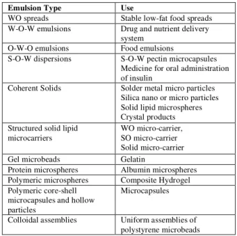
emulsion (WO) [5]. In OW, oil droplets are simply dispersed in water, however, it is more convenient to define OW emulsion as a dispersion of a water-immiscible liquid in an aqueous phase that is often called as oil regardless of its actual nature [6]. Common examples of OW emulsions include creams and mayonnaise. In WO, water droplets are dispersed in oil and this type of emulsion is a dispersion of an aqueous solution in a water-immiscible liquid, the reverse of OW emulsion. Common examples of WO emulsions include butter and spreads. (Fig. 2) depicts the two common emulsion types, whereas (Table 1) shows the summary of various other types of commonly used emulsions such as WO, water oil water (W-O-W) and solid oil water (S-(W-O-W) emulsions along with their uses. The enlisted emulsion types are used in many fields such as in mining, textile, photographic, chemical and polymer industry.
Figure 2. Representation of (a) Oil-Water (OW) emulsion in which oil is the dispersed phase and water is the continuous phase; (b) Water-Oil (WO) emulsion in which oil is the continuous phase and water is the dispersed phase.
Table 1.Emulsion types and their uses; O = oil, S = solid and W = water
Emulsion Type Use
WO spreads Stable low-fat food spreads W-O-W emulsions Drug and nutrient delivery
system O-W-O emulsions Food emulsions
S-O-W dispersions S-O-W pectin microcapsules Medicine for oral administration of insulin
Coherent Solids Solder metal micro particles Silica nano or micro particles Solid lipid microspheres Crystal products Structured solid lipid
microcarriers
WO micro-carrier, SO micro-carrier Solid micro-carrier
Gel microbeads Gelatin
Protein microspheres Albumin microspheres Polymeric microspheres Composite Hydrogel Polymeric core-shell
microcapsules and hollow particles
Microcapsules
Common to all, there are three basic conditions that must be met in preparing emulsions [5] i.e. i) the two liquids must be immiscible with each other, ii) sufficient agitation is provided to disperse one liquid into another, and iii) surfactant must be present. Also, there are other types of emulsified products produced widely in the process industry such as water-in-oil-in-water (W-O-W) and oil-in-water-in-oil (O-W-O) multiple emulsions (Fig. 3). In W-O-W multiple emulsions small water droplets are entrapped within larger oil droplets that in turn are dispersed in a continuous water phase, whereas O-W-O emulsions are the reverse of W-O-W emulsions [7]. Multiple emulsions are difficult to be produced as these are made by two successive homogenization steps and that they are susceptible to breakdown [4].
Figure 3. Representation of multiple water-oil-water (W/O/W) and oil-water-oil (O/W/O) emulsions.
Apart from the multiple emulsion types discussed above, there are also solid-in-oil-in-water (S-O-W) dispersions (Fig. 4).
Figure 4.Representation of solid-oil-water (S/O/W) emulsions.
Emulsion stability
Emulsion type and stability are known to be associated to the equilibrium phase behavior in surfactant-oil-water systems [8-10]. A stable emulsion means that one phase remains dispersed in the other. An unstable emulsion however means that two separate layers of liquid will occur after passing through several stages. When the droplets move in the system due to either stirring or diffusion, and if the repulsion potential is too
weak, the droplets aggregate resulting from one droplet to two separated by a thin film, a process generally referred to as flocculation [2]. The thickness of the thin film reduces due to the van der Waals attraction and the droplets coalesce to form large droplets. Due to the difference in phase between the dispersed and continuous phases, the droplets will either rise or sink depending on their density. Concentrated emulsions occur at the top or bottom of the container. The flocculation and coalescence will lead to large droplets until phase separation has occurred as shown in (Fig. 5).
Figure 5.Destabilization stages of emulsion.
Surfactants
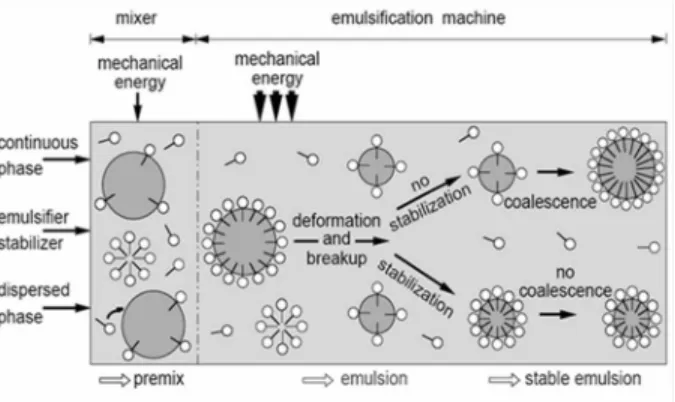
Emulsion stability can be regarded as the resistance of emulsions to the coalescence of their dispersed droplets [11]. The influence of surfactants, as represented in (Fig.6), on membrane emulsification is reported in the literature by various other researchers [12-19]. Surfactants lower the surface tension and facilitate the droplet distribution with stabilization. An emulsion is said to be unstable when the interface area between two immiscible liquids is increased, which results in a correspondingly large increase in the interfacial free energy of the system. Emulsifiers are defined as the surface active agents or surfactants with hydrophilic and lipophilic groups. Surfactants are semi-soluble in both organic and aqueous solvents and for this reason they are amphipathic.
In the production of emulsions, surfactants are used to stabilize the system by adsorption at the liquid-liquid interface as an oriented interfacial film. This film reduces the interfacial tension (γ) between the two liquids and decreases the rate of coalescence of the dispersed particles. In WO emulsions, the system is not stabilized simply by forming an adsorbed layer of surfactant to minimise the inter-particle forces. Therefore mechanical stabilization is said to be significant in these emulsions. As opposed to WO emulsions, OW emulsions are stabilised by adsorption of small-molecule emulsifiers [2]. Multiple emulsions i.e. W-O-W and O-W-O emulsions require two or more surfactants to be present in the system, one of which has a low Hydrophile-Lipophile Balance (HLB) value to stabilise the primary WO emulsion and the other with a high HLB value to stabilise the secondary OW emulsion. The surfactants commonly used together as an emulsifier for many applications include sorbitol ester (Span) and a poly-oxyethyleneated sorbitol ester (Tween) [11]. The process of stable emulsion formation is shown in (Fig. 7).
Figure 7. Formation of stable emulsion.
Conventional methods for emulsification
Conventional emulsification processes rely on stirring equipment, colloidal mills, homogenizers, ultrasonic or micro-fluidisers [20].
Rotor-stator system
In this method the emulsions are formed by introducing shear into the suspension. The shear is produced by the generation of eddies, caused by
vigorous stirring in the system (Fig. 8). The most common example of this type of system is Tooth-disc high speed homogenisers or colloid mills [21].
Figure 8. Oil-water (O/W) emulsification using rotor-stator equipment.
High pressure homogeniser system
In high pressure homogeniser system (Fig. 9) the emulsion mixtures are passed through a narrow orifice, or they can be homogenised by inject dispersion, in which two jets of different components are made to colloid head-on [21].
Figure 9.High pressure emulsification process.
Although the above mentioned methods are commonly used but these methods have some major inherent problems associated with their applications. Firstly the droplet size and size distribution cannot be easily controlled. Even if we are able to get the mean droplet size, the droplet size distribution will often be in a wide range. This in turn will have an effect on the emulsion characteristics and stability. Secondly, large scale production of emulsions using traditional (rotor-stator) methods is very energy-inefficient and the energy-inefficiency gets worse as the vessel size is increased and this adds significantly to the manufacturing cost. Thirdly, there is a major equipment reproduction problem even for a single piece of equipment. Also the conventional methods utilize a strong shearing stress which may
Droplet discuption in rotor-stator systems
o/w (fine emulsion)
o/w (pre-mix)
Droplet discuption in High-pressure systems
o/w (fine emulsion)
result in coalescence of the dispersed phase. The resulting emulsions may result in poly-dispersion with poorly controlled droplet size, which can affect the physicochemical properties of the emulsion. In addition, food products such as margarine contain flavouring components in the dispersed phase, which can adversely affect the
flavour of such products. The droplet size
distribution may also have an effect on bacterial growth. When the droplet diameter is large, bacteria multiply more easily than for smaller diameter droplets. For droplet break-up in a laminar flow field, the shear stress (τ) acting on a drop being deformed during emulsification is usually estimated as the product of the velocity gradient (G) and the continuous phase viscosity (µc) [22, 23].
τ = G µc (1) The product quality will usually vary from one manufacturing vessel design to another even if we design on the same manufacturing scale. It is all due to the above mentioned problems and other operational difficulties associated with the traditional emulsification systems that there has been an increasing interest in finding a new technique for making emulsions. One of the promising alternatives may be the use of membranes for the production of emulsions.
Membrane emulsification
The mechanism of droplets formation in membrane emulsification involves two stages: droplet growth and detachment [24, 25]. Membrane emulsification is a relatively new emulsification technology based on the use of micro porous membranes [7, 26, and 27]. In this process, the dispersed phase is pressed through the pores into the continuous phase where the droplets are formed. The droplets reaching a critical diameter detach from the membrane surface under the influence of shear forces caused by the flow of the continuous phase [28] or by use of a simple paddle stirrer to create shear at the surface of a flat disc regular array membrane [29, 30]. Membrane emulsification methods have received keen attention from many investigators [8, 14, 20, 31-43], especially in the last two decades, since it is able to control the droplet size and distribution by
selecting an appropriate pore size of the membrane in comparison to the turbulent breakup in conventional methods. The operation is carried out at low shear that result in energy saving since high shear equipment requiring high energy input are not used. In addition to energy savings, this technique is simple, needs less surfactant, and result in narrow and consistent droplet size of OW, WO and multiple emulsions. The process of micro porous membrane emulsification for oil and water systems is shown in (Fig. 10).
Figure 10.Emulsification techniques. Reprinted from [27].
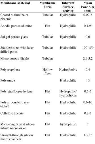
Membrane emulsification is a recently developed technique and its first use can be traced back in 1986 when Nakashima and Shimizu [26] carried out their experimental investigations to the use of this technology. The advancement made in the field of membrane technology emulsification has resulted in many different ways in which this technology can be used for the production of mono-sized particles, of which some worth-mentioning include: rotating membranes, repeated membrane extrusion of coarsely pre-emulsified feeds [27, 40 and 44]. Various membranes that are used for emulsification are summarized in (Table 2).
margarine OW or WO emulsions to multiple emulsions of different types; S-O-W dispersions, coherent solids (silica particles, solid lipid microspheres, solder metal powder) and structured solids (solid lipid microcarriers, gel microbeads, polymeric microspheres, core-shell microcapsules and hollow polymeric microparticles) and low-fat spreads.
Table 2. Different types of membranes used for emulsion Polymerization [41]
Membrane Material Membrane Form
Inherent Surface activity
Mean Pore Size
(nm) Coated α-alumina or
zirconia
Tubular Hydrophilic 0.02-3
Anodic porous alumina Flat Hydrophilic 0.125
Sol gel porous glass Tubular Hydrophilic 0.6
Stainless steel with laser drilled pores
Tubular Hydrophilic 100-150
Micro porous Nickle Tubular 2.9-5.2
Polypropylene Hollow
fiber
Hydrophobic 0.4
Polyamide Hydrophilic 10
Polytetrafluoroethylene Flat Hydrophilic/ hydrophobic
0.5-5
Polycarbonate, track-etched
Flat Hydrophilic 0.6-10
Cellulose acetate Flat Hydrophilic 0.2-3
Micro-engineered silicon nitride micro sieve
Flat hydrophilic 7
Straight-through silicon micro channels
Flat Hydrophilic 10-17
This method is also used in the manufacture of monodisperse colloidal particles: silica-hydrogel and polymer microspheres, porous and cross-linked polymer particles, including microspheres containing carbon black for toners. One of the most important applications of membrane emulsification technology is in obtaining multiple emulsions and micro-capsules, which have found an important application in pharmacy and chemotherapy. An example of micro-porous membrane emulsification is given in (Fig. 11).
Figure 11.Microporous membrane emulsification.
There has been an increasing interest in membrane emulsification technique due to its low energy requirement [40, 45]. The method of membrane emulsification has found a considerable development in many applications during the last two decades. The method of membrane emulsification involves the use of low pressure, typically 200 kPa, to force the dispersed phase to permeate through a tubular membrane having a uniform pore-size distribution into the continuous dispersion medium. The resulting droplet size is controlled primarily by the choice of membrane. It is important that the membrane should not be wetted by the phase to be dispersed [42]. Some membrane types investigated in previous works include shirasu-porous-glass [42], silicon and silicon nitride micro-sieves membranes [46-49], polycarbonate track-etch membranes (Millipore, inc.) [50], ceramic [16, 51], metallic, polymeric [36] and micro-engineered devices [20, 52-56]. They presented a general flow diagram on membrane emulsification process which is shown in (Fig. 12).
use of membrane surface coating techniques can be employed to control the philicity and hydro-phobicity of the membrane surface such as the use of silicone resin to coat Shirasu Porous glass membrane surface [47, 57].
Figure 12. Membrane emulsification application diagram.
Factors affecting the distribution of droplets in membrane emulsification
Pore size
The average droplet size produced by the micro-porous membrane can be determined by the size of the pore opening [58]. In case the pore openings at the membrane surface are not circular then this necessitates the need for determining the equivalent pore diameter, which can be obtained by Equation 2:
ddr (m) = xdp (2)
Where, ddr represents the droplet size and dp is the
pore diameter. The value of x is usually between 2 and 10, depending on the ingredients used. To obtain results from Equation 2, a minimum cross-flow velocity (or wall shear stress) is required. If this requirement is not met, x can become an order of magnitude larger and the obtained emulsions are more poly-disperse [59]. However, Christov et al. [39] claims that under specific conditions, theoretically the droplet size should be three times the pore size without a cross-flow. In this case, the trans-membrane pressure must be very close to the
critical pressure of the pores (within 10%) which will yield a very low flux.
Shape of the pore opening
Kobayashi et al. [60] had found a ratio of droplet to pore size equivalent to 2, using a silicon membrane with oblong pores and very low cross flow velocities. The equivalent pore size was defined as four times the cross-sectional area divided by the wetted perimeter of the channel. The ratio of droplet to pore size was found to be independent from the cross-flow velocity and the trans-membrane pressure [59].
Membrane surface porosity
Experiments with a micro-sieve showed that steric hindrance of droplets forming simultaneously results in poly-disperse emulsions [60]. Therefore, the surface porosity should be low enough to prevent any hindrance but not so close to result in coalescence [58, 61]. The droplets will be deformed in the direction of flow depending on the cross flow velocity, so it will be necessary to increase the trans-membrane pressure, to obtain a disperse phase flux that makes industrial application feasible. As the fraction of active pores will increase the chances of steric hindrance will also increase. The maximum porosity to be used while preventing steric hindrance and coalescence if all pores are active can be estimated by assuming a square array of pores. The distance between the pores should at least be equal to the droplet diameter. The porosity ( ) then follows as given in Equation 3 [59]:
2
2 2
1 25 . 0 25
. 0
x d
d
dr
p
(3)
Membrane thickness
Wall contact angle
In common operation, the membrane should be wetted with the continuous phase to obtain droplets of the disperse phase; hence the wall contact angle, scd, (measured in the continuous phase) should be smaller than 90°. From Young’s equation, it follows that the wall contact angle ( scd) is a function of the properties of the two immiscible liquids and the solid as given in Equations 4 and 5:
scd cd
sd
sc
cos
(4)Or
cd sc sd
scd
cos
(5)
Where sd and sc are the interfacial tensions of the
respective boundary of solid/disperse phase and solid/continuous phases, and cd is the interfacial
tension between the two liquid phases. The interfacial tensions between the liquids and the solid may be different for different emulsifiers.he interfacial tension between the two liquids largely depends on the expansion rate determined by the disperse phase flux, and on the concentration and type of emulsifier. Thus, it can be summarised that the wall contact angle of the membrane depends on the dynamics of the emulsifier [59].
Trance membrane pressure and cross-flow velocity
Trance membrane pressure (∆Ptm) forces
the dispersed phase to permeate through the membrane into the continuous phase [15, 16, 31, 37 and 62].
2
, ,in cout c
d tm
P P P
P
(6)
Where is the mean pressure of the continuous phase, and are the pressure of the respective flowing continuous phase at the inlet and outlet of the membrane device. The droplets formed at the membrane surface detach under the shear stress of the continuous phase [31, 37, 51, 58, and 60].
Review of membrane emulsification techniques
The membrane emulsification technique has been highly attractive mainly due to its simplicity, potentially low energy consumption, need for less surfactant and resulting narrow droplet-size distributions [63, 64]. The influence of different factors on emulsification process by employing micro-porous membranes is investigated by many researchers and it was observed and demonstrated that by selecting appropriate operating conditions and/or parameters e.g. cross-flow velocity, emulsifier concentration and dispersed phase flux through the membrane, emulsions with a narrow droplet-size distribution and an average droplet size of roughly five times the nominal membrane pore size can been produced [7, 8, 16, 32, 33, 35, 65, 66]. In general, the flux of dispersed phase through a membrane tends to be quite low for producing emulsions with narrow droplet-size distributions. Fluxes for producing OW emulsions range typically from 2 to 40 l m−2 h−1 for membranes having a nominal pore size from 0.2 to 0.8 m, respectively [14, 16, 42 and 65]. In comparison, fluxes of 2300 l m−2 h−1 were achieved using an oil-pre-treated, 1.0 m pore-size hydrophilic membrane to produce WO emulsions and 200 l m−2 h−1 using a 0.5 m pore size membrane [65]. This flux was sufficient to lead to the industrial production of a low-fat WO emulsion spread. At higher fluxes the average droplet size tends to increase because of the increased droplet coalescence at the membrane surface.
Teflon®) membranes have also been tried in membrane emulsification. However, it is reported that in the use of PTFE membrane pre-emulsification is necessary in order to obtain a narrow droplet size distribution. In practice a WO emulsion is pushed through the PTFE membrane and into the aqueous phase to obtain an OW emulsion and vice versa for the preparation of WO emulsions. However by using this method, it is difficult to control the droplet size in the final emulsion [57]. Early laboratory investigations into membrane emulsification involved the use of a coated ceramic membrane and the porous glass membrane. Peng and Williams [24, 25] studied the effect of some of the fundamental process parameter for OW emulsion controlling the droplet formation from an individual pore with the use of a high-speed video camera. This high-speed video photography technique to monitor the evolution of droplets emerging from a single pore under cross-flow conditions has been employed successfully to verify a design model for cross flow membrane emulsification. It was demonstrated in their work that the droplet size and the number production rate are predictable and controllable [24, 25]. Yamazaki et al. [57] investigated the potential of PTFE membranes as water-in-oil emulsification device to obtain the uniformly sized droplets and to convert them into microcapsules and polymer particles via subsequent treatments [57]. As a first step, they compared the performance of a hydro-philically treated PTFE membrane with that of a Shirasu Porous glass (SPG) membranes. It was reported that the characteristics of emulsions prepared with the PTFE membrane were tolerable but not to the same degree as those prepared with SPG membranes since the SPG membrane was more hydrophilic than the PTFE membrane. After the modification of the membrane pore size, the hydrophilic PTFE membrane could control the droplet size by selecting a nominal pore size. There are a number of factors which control the drop size distribution in the formed emulsion. Lot of work has been done to examine these factors. Christov et al. [39] investigated the role of surfactant adsorption and dynamic interfacial tension and the effect of membrane hydro-philicity on the droplet size distribution in the presence of the non-ionic Tween 20, and milk proteins Na-caseinate and beta-lactoglobulin (BLG) using Shirasu porous glass emulsification technique [39]. In contrast
with the preceding studies, in which the emulsion drops have been formed at the inner surface of a tubular membrane, they employed a special setup for producing the drops at the outer membrane surface. A relatively fine and mono-disperse oil-in-water emulsion with a mean drop diameter of about three times than that of the pore was obtained using Tween 20. In contrast, for the lower concentration of Tween 20, as well as for the investigated solution of Na-caseinate and BLG, the membrane was covered by a layer of growing attached emulsion drops, which were poly-dispersed, with a relatively large mean droplet size. Any pronounced coalescence of oil drops has not yet been reported in the investigated emulsions. The generation of large and poly-disperse oil drops in some of the studied solutions is attributed mostly to the effect of expansion of the drop contact line and formation of hydro-phobised domains on the membrane surface. Therefore, any factor which leads to the decrease of dynamic three-phase contact angle, and thus prevents the contact-line expansion, facilitates the production of fine and mono-disperse emulsions [39].
Polymerization
Chain growth polymerization
In chain-growth Polymerization, single-monomer molecules react successively and rapidly with the growing polymer chain, and large macromolecules are formed almost immediately [75]. The life time of a growing polymer molecule may be less than a few seconds for a free-radical Polymerization, which is a typical example of chain-growth Polymerization, while a typical Polymerization time to obtain high monomer conversion may be of several hours. Chain-growth Polymerization requires an active centre, which may be a free-radical, cation, or anion. Once an active centre is created, a polymer chain grows extremely rapidly, and when the growing chain is deactivated by a termination reaction, the polymer chain is dead and no longer takes part as a reactant. Chain-growth Polymerization is initiated by a reactive species, produced from an initiator or catalyst. Depending on the type of active centre, chain-growth Polymerization can be divided into free-radical, anionic, and cationic Polymerization.
Step-growth growth polymerization
In step-growth Polymerization, the molecules build up slowly; Polymerization takes place between two monomer molecules, a monomer and polymer segment, or two polymer segments [76]. Usually, a step-growth Polymerization is relatively slow and must be continued to a very high conversion to attain sufficiently high molecular weights. Usually, a bi-functional monomer is linked via the reaction of the functional groups to another monomer or polymer segment but there are no specific initiators. The polymer is always capable of reacting with another monomer or polymer segment unless the propagating functional groups are terminated via a reaction with a mono-functional molecule or some contaminant. If the reaction between the functional groups splits off a small molecule, it may be necessary to remove such molecule to attain a required polymer size. Step-growth Polymerization can be divided into linear, nonlinear, and interfacial Polymerization. It is customary to characterize a Polymerization further by the nature of the phase, or system of phases in which the reactants and products are
formed. Polymerization can either be carried out under homogenous or heterogeneous conditions. This classification is based on whether the initial reaction mixture is homogeneous or heterogeneous even though some homogeneous systems turn heterogeneous as Polymerization proceeds.
Emulsion Polymerization
In emulsion Polymerization, the initial reaction mixture consists of two separate phases and Polymerization continues in a heterogeneous manner throughout [72]. Fine drops are produced in emulsion Polymerization. Particle size of product in this case is not related to drop size but is related to the surfactant micelle size. In emulsion Polymerization the monomer is emulsified in a medium, generally water, with the aid of emulsifying agent such as soap and alkyl sulfonate. Emulsion Polymerization differs primarily from suspension Polymerization in that the initiator is maintained in the aqueous phase. The principle distinction between these two is therefore the Polymerization process rather than the presence of emulsifier. Polymer particle formed in emulsion Polymerization are usually much smaller than those produced in suspension Polymerization. In comparison to the other Polymerization techniques the main advantage of emulsion Polymerization is that high molecular weight polymers can be produced while a high reaction rate is simultaneously maintained, these two factors cannot be increased simultaneously in any other Polymerization technique. However, the presence of emulsifier and other additives in the final product and the need for purification of the polymer limit its use.
Polymerization using membrane emulsification technique
changes of polymer particles on hydrophobic and/or hydrophilic additives [77, 78]. The emulsion droplets of styrene/acrylate monomer in the presence of a crosslink agent and hydrophobic/hydrophilic additives were produced using Shirasu porous glass membrane technique. Suspension co-polymerization was then carried out to obtain the prospective polymeric particles. It was found that the particle size decreased with a narrow size distribution when the additives were changed from long-chain alkanes to long-chain alcohols and long chain esters, respectively. Various microspheres with different morphologies were obtained, depending on the composition of oil phase. The spherical particles without phase separation were obtained using an adequate amount of the cross linking agent and methyl palmitates as an additive. Yuyama et al. [62] studied the mechanism of suspension polymerization of uniform monomer droplets, without coalescence and breakup during the polymerization [62]. The glass membrane (Shirasu porous Glass, SPG) emulsification technique was employed and styrene as a monomer mixed with water-insoluble hexadecane (HD) was used for investigation. The results obtained show that, by the addition of hexadecane, the droplets were stable, without coalescence and breakup during polymerization. The styrene/HD mixture was rather incompatible with polystyrene, implying that the polystyrene radicals were isolated in tiny compartments (cells) dissolved in styrene rich medium. These cells were surrounded by the styrene hexadecane phase. Without the addition of HD, no phase transition was observed, and the polymerization behaved as an ordinary suspension polymerization. The stability of monomer droplets was no longer maintained in the runs without the addition of HD in the oil phase and sodium nitrate in the aqueous phase. The experiments made clear that water-insoluble substance (HD) and the water soluble inhibitor (sodium nitrate) were both essential for the preparation of uniform-sized polymer particles using the SPG emulsification technique [62].
Phase inversion
Phase inversion is defined as phases of liquid-liquid dispersion interchange such that the dispersed phase spontaneously inverts to become
the continuous phase and vice versa under conditions determined by the system properties, volume ratio and energy input [79]. OW emulsions may be changed to WO emulsions and vice versa depending on the order of addition of the phases, the nature of surfactant, phase volume ratio, phase in which the surfactant is dissolved, temperature of the system, electrolyte and the additive content [11]. The temperature at which inversion occurs is the temperature where the hydrophilic and lipophilic tendencies of the surfactant in the system are balanced. This is known as phase inversion temperature (PIT), also called low-energy emulsification method. Phase inversion behaviour is affected by the physical properties such as viscosity, density and interfacial tension, and also geometric factors such as agitation speed and position of the impeller. Break-up of droplets occur under the action of turbulent flow and resisting this break-up is the interfacial tension of the droplet. Surfactants prevent coalescence due to their chemical structure and reduce interfacial tension. They greatly reduce the drop sizes and produce stable emulsions. As discussed earlier the emulsions may be prepared mechanically which involves high-energy input normally achieved by high-sheer stirring, high-pressure homogenisers or ultrasound generators [80]. The input of high energy results in the breakage into smaller droplets provided the Laplace pressure is overcome. Moreover, small droplets require more energy and/or surfactant to remain stable, which in turn make these methods unfavourable in commercial industrial applications when small droplets are required. Phase inversion can be one of the solutions to overcome this problem, where the change of the continuous phase will lead to a system which can be desirable, for example in the manufacture of low fat spreads [81].
Mechanism and formation of multiple emulsions
oil droplets which allows them to coalesce. The critical volume fraction of the dispersed phase to which the inversion occurs is the phase inversion point [82]. When an emulsion is near the phase inversion point a multiple emulsion may form such as W-O-W or O-W-O emulsions. Phase inversion point can be detected by measuring changes in electrical conductivity. The main advantage of phase inversion in producing emulsions is the possibility of producing very fine particles with minimum consumed energy [81, 83]. There are two types of phase inversions, catastrophic and transitional inversion. The former occurs by changing the ratio in volume fraction of water phase to the dispersed phase; and the latter occurs by changing the nature of surfactant or in other words phase inversion by Hydrophile-Lipophile (HLB) balance of the surfactant system [76]. However, catastrophic inversion often produces large drop size. HLB of a system is related to the locus of aggregate formation in equilibrated mixtures [10]. In the OW system, water phase contains surfactant micelles or the oil phase contains dissolved surfactant at its critical micelle concentration (CMC). Surfactants with high HLB value are more hydrophilic end tend to form O/W emulsions. In the WO system, however, the water phase contains dissolved surfactant at its CMC, or the oil phase containing surfactant micelles, with the HLB values being lower. The mechanism of different types of phase inversion depends on surfactant types [76]. The hydrophilic part of a surfactant is soluble in the aqueous phase, whereas the lipophilic part is soluble in oil. The role of surfactant in OW and WO emulsions is shown diagrammatically in (Fig. 13).
Figure 13. Representation of an Oil-water (O/W) and water-oil (W/O) microemulsion.
Quantitative relationships
Arirachakaran et al. [84] suggested the empirical model for the prediction of the phase inversion point as given in Equation 7.
r o I m ws I wU
U
0
.
5
0
.
11081
log
(7)
Where,
wI is the critical water cut for phaseinversion; Uws is the water superficial velocity; Um
is the mixture superficial velocity, ηo is the oil
viscosity and ηr equals to 1 mPa s. It has been
suggested in literature [78] that phase inversion occurs at the point where the surface energies of the two possible dispersions within the range of volume fractions are equal [81-84]. The critical oil hold-up for phase inversion is correlated by Equation 8. W O O W O W I o d d s d / 32 / 32 / 32 cos 6
(8)Where σ is interfacial tension; θ is the liquid/solid surface contact angle (0 ≤ θ < 90º denotes hydrophilic surface or surface wetted by water and
90 < θ ≤ 180º denotes hydrophobic surface i.e. surface wetted by oil); s = 4/D is the solid surface per unit volume (D is pipe diameter); d32 is the
Sauter mean diameter
i i i i i i d n d n 2 3and is found
using maximum drop size (dmax) and kd values from
the relation d32 = dmax/ kd, where kd is constant
depending on the fluid system used, while dmax can
be found from the correlation given by Equation 9.
6 . 0 4 . 0 6 . 0 2 ~ max 1 1 22 . 2 d d d c m c c H f D U C D d (9)Where, CH
~
is a tenable constant; Uc is the continuous phase velocity; ρc and ρm is the density
is the wall friction factor and εd is the dispersed
phase hold-up. Bouchama et al. [85] studied the mechanism of catastrophic phase inversion on the basis of multiple emulsion formation consist of paraffin oil, water and Triton X-100 [85]. In their studies, they showed that the locus of catastrophic phase inversion is determined by the added volume of the dispersed phase at each step of the dilution rather than the addition step. However, Brooks and Richmond [86] reported the drop size distribution during catastrophic phase inversion was found to depend on stirring speed and on the addition rate of the aqueous phase [86]. They also mentioned that the formation of oil-in-water-in-oil drops and the choice of surfactant are important. Recently, Xie and Brooks [76] developed phase inversion maps, showing the behaviour of the emulsion system as a function of HLB and water volume fraction. Shinoda and Saito [87] introduced the phase inversion temperature (PIT) method which is widely used in the industry [87]. This method takes advantage of the extremely low interfacial tensions achieved at the HLB temperature or PIT to promote emulsification [88]. Tadros et al. [89] reported the formation of OW nano-emulsions with controlled droplet diameters in the range of 50-160 nm using this PIT method [89].
Conclusions
From the investigations that were aimed at looking into the production of emulsions, membrane emulsification showed a great potential in manufacturing the very accurate size mono-dispersed emulsions and other solid particulates. The process has proved reliable in comparison to others and can be used for large-scale productions. Scale-up for this process is easy than the other emulsification processes. Single (WO or OW) and/or multiple (W-O-W, E-O-W or O-W-O) emulsions with various droplets size ranging from
0.8 to over 100 μm, with a typical coefficient of
variation between 10–15%, have been reported to be successfully prepared by employing different pore sizes and types of membranes. Direct membrane emulsification can become a very attractive technique for small-scale manufacture of low viscosity, low concentration emulsion products, due to its high capability of droplet size and distribution controls but at limited emulsifying rate. Premix membrane emulsification is suitable
for large-scale manufacture of high concentration emulsion products, due to high emulsifying rate and simple operation. Emulsion Polymerization is most commonly employed in the formation of mono-disperse polymer particles. Phase inversion is a complex phenomenon but it is particularly useful when the final emulsion is subject to specifications that are unattainable using conventional methods as in the case of producing tiny droplets of highly viscous oil.
References
1.
S. E. Friberg, K. Larsson and J. Sjblöm, Food Emulsions, (Marcel Dekker Inc. New York), 4/e (2004).2.
J. Sjöblom, Emulsions and Emulsion Stability, (Surfactant Science Series, Marcel Dekker, Inc., New York), 61 (1996).3.
C. Charcosset, J. Food Sci., 92 (2009) 241.4.
D. G. Dalgleish, Food Hydrocoll. 20 (2006) 415.5.
G. Chen and D. Tao, Fuel Processing, 86 (2005) 499.6.
H. S. Ribeiro, L. G. Rico, G. G. Badolato and H. Schubert, J. Food Sci. 70 (2005) 117.7.
C. Charcosset and H. Fessi, Reviews Chem. Eng. 21 (2005) 1.8.
C. Charcosset, I. Limayem and H. Fessi, J Chem. Technol. Biotechnol, 79 (2004) 209.9.
J. Jiao and D. J. Burgess, AAPS Pharma Sci (http://www.pharmsci.org)7 (2003) 1.10.
B. P. Binks, W. G. Cho, P. D. I. Fletcher and N. Petsev, Langmuir, 16 (2000) 1025.11.
M. J. Rosen, Surfactants and interfacial phenomena, (John Wiley & Sons, New York) (1978).12.
K. Kandori, K. Kishi and T. Ishikawa, Colloid. Surf., 61 (1991a) 269.13.
K. Kandori, K. Kishi, T. Ishikawa, Colloid. Surf., 55 (1991) 73.14.
G. Muschiolik, S. Dräger, I. Scherze, H. M. Rawel and M. Stang, Food colloids: proteins, lipids and polysaccharides. Cambridge: Royal Society of Chemistry, (1997) 393.16.
V. Schröder and H. Schubert, Colloids and Surfaces A: Physicochemical and Engineering Aspects, 152 (1999) 103.17.
T. Fuchigami, M. Toki and K. Nakanishi, J. Sol-Gel Sci. Technol., 19 (2000) 337.18.
H. Yuyama, T. Watanabe, G-H. Ma, M. Nagai and S. Omi, Coll. Surf. A, 168 (2000) 159.19.
I. Kobayashi, M. Yasuno, S. Iwamoto, A. Shono, K. Satoh and M. Nakajima, Coll. Surf. A, 207 (2002) 185.20.
K. Sotoyama, Y. Asano, K. Ihara and K. Takahashi, J. Food Sci. 64 (1999) 211.21.
H. Karbstein and H. Schubert, Chem. Engg. Process, 34 (1995) 205.22.
J. Adler-Nissen, S. L. Mason and C. Jacobsen, Trans. Inst. Chem. Engg., 82 (2004) 311.23.
P. Walstra, Chem. Eng. Sci., 48 (1993) 333.24.
S. J. Peng and R. A. Williams, Trans. Inst. Chem. Engg., 76 (1998) 894.25.
S. J. Peng and R. A. Williams, Trans. Inst. Chem. Engg., 15 (1998) 21.26.
T. Nakashima and M. Shimizu, Ceramics Japan, 21 (1986) 408.27.
N. Aryanti, R. A. Williams, R. Hou and G.T. Vladisavljević, Desalination, 200 (2006) 572.
28.
S. R. Kasvintsev, G. Gasparini and R. G. Holdich, J. Membrane sci., 313 (2008) 182.29.
E. Egidi, G. Gasparini, R. G. Holdich, G. T.Vladisavljević and S. R. Kosvintsev, J. Membrane Sci., 323 (2008) 414.
30.
M. T. Stillwell, R. G. Holdich, S. R. Kosvintsev, G. Gasparini and I. W. Cumming, Ind. Engg. Chem. Res., 46 (2007) 965.31.
R. Katoh, Y. Asano, A. Furuya, K. Sotoyama and M. Tomita, J. Membrane Sci., 113 (1996) 131.32.
S. M. Joscelyne and G. Trägårdh, J. Membrane Sci., 169 (2000) 107.33.
A. J. Gijsbertsen-Abrahamse, A. Van der Padt and R. M. Boom, J. Membrane Sci., 230 (2004) 149.34.
V. van der Graaf, C. G. P. H. Schroën and R. M. Boom, J. Membrane Sci. 251 (2005) 7.35.
G. T. Valdisavlijević and R. A. Williams,Adv. Coll. Interf. Sci., 113 (2005) 1.
36.
K. Suzuki, I. Fujiki and Y. Hagura, , Food Sci. Technol., 4 (1998) 164.37.
I. Scherze, K. Marzilger and G. Muschiolik, Coll. Surf. B, 12 (1999) 213.38.
Y. Asano and K. Sotoyama, Food Chem., 66 (1999) 327.39.
N. C. Christov, D. N. Ganchev, N. D. Vassileva, N. D. Denkov, K. D. Danov and P. A. Kralchevsky, Colloid Surface A, 209 (2002) 83.40.
K. Kandori, Food Processing: Recent Developments, (1995) 113.41.
G. T. Valadisavljević, S. Tesch and H. Schubert, Chem. Eng. Process, 41 (2002) 231.42.
T. Nakashima, M. Shimizu and M. Kukizaki, Key Engineering Materials, 61-62 (1991) 513.43.
C. J. Cheng, L. Y. Chu and R. Xie, J. Coll. Interf. Sci., 300 (2006) 375.44.
G. Muschiolik and H. Bunjes, Multiple Emsulsionen, BEHR’S VERLAG (13th World Congress of Food Science &Technology iufost, DOI:
10.1051/IUFoST:2006004) (2007),
Available online
http://iufost.edpsciences.org/index.php?optio n=com_article&access=standard&Itemid=12 9&url=/articles/iufost/pdf/2006/01/iufost060 00043.pdf, accessed on 28/11/2012 at 1923GMT.
45.
M. T. Ravanchi, T. Kaghazchi and A. Kargari, Desalination, 235 (2009) 199.46.
J. Zhu and D. Barrow, J. membrane Sci. Technol., 19 (2005) 176.47.
M. J. Geerken, R. G. H. Lammertink, M. Wessling, Coll. Surf. A, 292 (2007) 224.48.
G. Brans, J. Kromkamp, N. Pek, J. Gielen, J. Heck, C. J. M. van Rijn, R. G. M. van der Sman, C. G. P. H. Schröen and R. M. Boom, J. Membrane Sci., 278 (2006) 344.49.
G. Brans, R. G. M. van der Sman, C. G. P. H. Schröen, A. van der Padt, R. M. Boom, J. Membrane Sci., 278 (2006) 239.50.
R. Tangirala, R. Revanur, T. P. Russell and T. Emrick, Langmuir, 23 (2007) 965.52.
N. Yamazaki, K. Naganuma, M. Nagai, G.-H. Ma and S. Omi, J. Disper. Sci. Technol., 24 (2003) 249.53.
L. Giorno, N. Li and E. Drioli, J. Membrane Sci., 217 (2003) 173.54.
L. Giorno, R. Mazzei, M. Oriolo, G. De Luca, M. Davoli and E. Drioli, J. Coll. Interf. Sci., 287 (2005) 612.55.
N. Müller-Fischer, H. Bleuler and E. J. Windhab, Chem. Eng. Sci., 62 (2007) 4409.56.
K. Hosoya, M. Bendo, N. Tanaka, Y. Watabe, T. Ikegami, H. Minakuchi and K. Nakanishi, Macromol. Mater. Engg., 290 (2005) 753.57.
N. Yamazaki, H. Yuyama, M. Nagai, G.H. Ma and S. Omi, J Dispersion Sci. Tech., 23 (2002) 279.58.
R. A. Williams, S. J. Peng, D. A. Wheeler, N. C. Morley, D. Taylor, M. Whalley and D. W. Houldsworth, Chem. Eng. Res. Des., 76 (1998) 902.59.
A. J. Gijsbertsen-Abrahamse., A. Van der Padt and R. M. Boom, J. Membrane Sci., 217 (2003) 141.60.
M. Kobayashi, K. Nakajima, Y. Chun, Kikuchi and H. Fujita, AIChE Journal, 48 (2002b) 1639.61.
A. J. Abrahamse, R. van Lierop, R. J. M. van der Sman, A. van der Padt and R. M. Boom, J. Membrane Sci., 204 (2002) 125.62.
H. Yuyama, G. H. Ma, M. Nagai and S. Omi, J. Appl. Polym. Sci., 78 (2000b) 1025.63.
E. Dickinson, Emulsions and droplet size control In: D. J. Wedlock (ed.), Controlled particle, droplet and bubble formation (Oxford: Butterworth-Heinemann) (1994).64.
A. Laouini, H. Fessi and C. Charcosset, J. Membrane Sci., 423–424 (2012) 85.65.
R. Katoh, Y. Asano, A. Furuya, K. Sotoyama and M. Tomita, (Proceedings of the 7th International Symposium on Synthetic Membranes in Science, Tübingen, Germany) (1994) 407.66.
Y. Mine, M. Shimizu and T. Nakashima, Colloid Surface B, 6 (1996) 261.67.
W. Banks and D. D. Muir, Stability of alcohol-containing emulsions In: E. Dickinson & G. Stainsby (Eds.), Advancesin Food Emulsions and Foams (London: Elsevier Applied Science Publishers) (1988).

![Figure 10. Emulsification techniques. Reprinted from [27].](https://thumb-eu.123doks.com/thumbv2/123dok_br/18277605.345248/5.918.471.811.326.492/figure-emulsification-techniques-reprinted-from.webp)