Francisco Coelho Petrucci Albuquerque
Porting of LTZVisor to the
Zynq Ultrascale+ MPSoC ZCU102 Board
Julho de 2019
Francisco Coelho Petrucci Albuquerque
Porting of LTZVisor to the
Zynq Ultrascale+ MPSoC ZCU102 Board
Dissertação de Mestrado
Mestrado Integrado em Engenharia Eletrónica Industrial e
Computadores
Sistemas Embebidos
Trabalho efectuado sob a orientação do
Professor Sandro Pinto
Julho de 2019Nome: Francisco Coelho Petrucci Albuquerque Correio Eletrónico: a70585@alunos.uminho.pt Cartão de Cidadão: 14236133
Titulo da dissertação: Porting of LTZVisor to the Zynq Ultrascale+ MPSoC ZCU102 Board Ano de conclusão: 2019
Orientador: Professor Doutor Sandro Pinto
Designação do Mestrado: Ciclo de Estudos Integrados Conducentes ao Grau de Mestre em Engenharia Eletrónica Industrial e Computadores
Área de Especialização: Sistemas Embebidos e Computadores Escola de Engenharia
Departamento de Eletrónica Industrial
De acordo com a legislação em vigor, não é permitida a reprodução de qualquer parte desta dissertação.
Universidade do Minho, 10/07/2019
Assinatura: Francisco Coelho Petrucci Albuquerque
DIREITOS DE AUTOR E CONDIÇÕES DE UTILIZAÇÃO DO TRABALHO POR TERCEIROS
Este é um trabalho académico que pode ser utilizado por terceiros desde que respeitadas as regras e boas práticas internacionalmente aceites, no que concerne aos direitos de autor e direitos conexos. Assim, o presente trabalho pode ser utilizado nos termos previstos na licença abaixo indicada.
Caso o utilizador necessite de permissão para poder fazer um uso do trabalho em condições não previstas no licenciamento indicado, deverá contactar o autor, através do RepositóriUM da Universidade do Minho.
Licença concedida aos utilizadores deste trabalho
Atribuição CC BY
”A man must go forth from where he stands. He cannot jump to the absolute; he must evolve towards it”. It is with this dissertation that I complete a journey lasting 18 continuous years of being a student. This uphill walk culminates in a similarly challenging finale, which would not be possible without the aid and accompaniment of family, friends, and academic colleagues.
Foremost, I thank my advisor, Sandro Pinto, whose own investigation was the parent of this dissertation’s theme, thus representing the main root from which this project blossomed. He served as the main counselor when crucial decision-making was required while infecting his advisees with a relaxed and productive work mood. This lab environment was also possible thanks to ESRG’s current Ph.D. students, whose maturity depicted a source of inspiration and pertinent suggestions for the progression of this project.
I cannot proceed without acknowledging the efforts of my lab colleagues — Ailton Lopes, Ângelo Oliveira, Hugo Araújo, José Ribeiro, José Silva, Nuno Silva, Pedro Machado, Ricardo Roriz and Sérgio Pereira — who cooperated mutually with me to solve the surging issues and surpassing our own engineering and personal skills as a team. Concurrently, the interaction with other colleagues of my degree, — mainly André Teixeira, António Dias, and Nuno Pereira — fed my curiosity with trivial and scientific domains beyond embedded systems development.
A big shout-out to the members of Onysus — André Lopes, André Pacheco, Daniel Rodrigues, and Pedro Coelho — whose constant creativity stimulus and synergistic activities deepened my soft skills and sparked unique points of view. Not to forget the daily attendance of my causal but noteworthy friends, who occasionally tempted me into tasks of leisure, refreshing my often deep and stagnant thoughts which allowed me to take one step back and two leaps forward.
Last but certainly not least, my sincerest gratitude to all the family members whom I have the absolute gratefulness of getting to know and love throughout all my life. It is with their continuous support that I have thrived into an individual and engineer that makes them proud to have watched grow.
STATEMENT OF INTEGRITY
I hereby declare having conducted this academic work with integrity. I confirm that I have not used plagiarism or any form of undue use of information or falsification of results along the process leading to its elaboration.
scale+ MPSoC ZCU102
Atualmente, a tecnologia computacional está a expandir-se para áreas que pareciam inal-cançáveis nas suas etapas primordiais, substituindo os tradicionais modelos de propósito único por aplicações modernas de propósito geral focadas em conectividade, ubiquidade e segurança. Devido a esta constante remodelação de métricas, é importante desenhar novas soluções desde as fases iniciais de desenvolvimento, tendo em conta as características do sistema a nível arqui-tectural. De facto, muitos fabricantes estão determinados a melhorar os dispositivos dos dias de hoje de modo a providenciarem vários serviços através do seu hardware, libertando o software para se dedicar a aplicações de propósito geral.
Com o crescimento da virtualização, é possível aplicar funcionalidades de componentes fisi-camente absentes num único processador, resultando na utilização de menos dispositivos mas também de unidades de processamento mais potentes. Em sistemas de tempo-real, este au-mento de funcionalidades torna-se prejudicial visto que sobrecarrega a execução com demasi-adas operações. Ao se projetar dispositivos desde as primeiras fases com estas considerações, é possível fazer com que estes cargos deixem de ser encarregues a software, sendo portanto garantidos pelas capacidades arquiteturais das plataformas. Deste modo, a virtualização assis-tida por hardware consegue equilibrar toda a carga de um sistema entre os domínios do software e do hardware.
Esta dissertação apresenta o processo de ”porting” de uma solução de virtualização assistida por TrustZone (LTZVisor) pelas últimas arquiteturas de alto desempenho da ARM. Esta migração entre arquiteturas implica uma alteração de plataforma, como a surgente e heterogénea Zynq Ultrascale+ MPSoC da Xilinx, adotada como placa de desenvolvimento deste projeto. É indicado como as capacidades da arquitetura emergente podem ser manuseadas de modo a implementar cenários de virtualização com pouca carga, sugerindo métodos para as aplicar em ambientes de execução leves e seguros. Estas abordagens foram validadas através da integração e avaliação de máquinas virtuais de tempo-real com privilégios distintos, onde os hóspedes prosperaram sem interferirem um com o outro.
Palavras-Chave: Arquitetura ARM, LTZVisor, Zynq Ultrascale+ viii
MPSoC ZCU102
Presently, computing technology is expanding towards realms that seemed unrealistic at the stages of its emergence, shifting from traditional single-purpose designs to modern general-purpose appliances centred around connectivity, ubiquity, and security. With this constant re-shaping of metrics, it is important to devise new solutions from the onset, taking into account the system’s features at the architecture level. In fact, many manufacturers are motivated in improving nowadays’ devices to wield powerful services in their hardware, liberating software to expand on general-purpose applications.
With the rise of virtualization, it is possible to apply the functionalities of physically absent components on a single processor, leading to the employment of fewer devices but requiring more powerful processing units. In systems with real-time requirements, this increase in overhead is prejudicial as it overloads execution with too many operations. By designing devices from the onset with those functions in mind, software ceases to handle such complex and time-consuming roles, which are guaranteed by the platform’s architectural features instead. Thus, hardware-assisted virtualization technologies balance out the total system workload between the software and hardware domains.
This dissertation presents the porting process of a TrustZone-assisted virtualization solution (LTZVisor) through ARM’s latest high-performance architectures. This change in architecture en-tails a transfer to newer embedded platforms, like the state-of-the-art heterogeneous Zynq Ultra-scale+ MPSoC from Xilinx adopted as the target board for this project. It is mentioned how the emergent architecture capabilities can be handled to implement virtualized scenarios with low overhead, suggesting methods to apply them in a secure and lightweight execution environment. These approaches were validated through the integration and evaluation of real-time virtual ma-chines with distinct privileges, where the performance sensitive guests thrived without interfering with one another.
Keywords: ARM Architecture, LTZVisor, Zynq Ultrascale+
List of Figures xiii
List of Tables xiv
List of Listings xv Glossary xvi 1 Introduction 1 1.1 Motivation . . . 1 1.2 Goals . . . 3 1.3 Document Organization . . . 3
2 Background & State of the Art 5 2.1 Fundamental Concepts . . . 5 2.1.1 Virtualization . . . 5 2.1.2 Hypervisor . . . 8 2.1.3 ARM Architecture . . . 10 2.2 Related Work . . . 34 2.2.1 Jailhouse . . . 35 2.2.2 VOSYSmonitor . . . 37
3 Platform and Tools 39 3.1 Platforms . . . 39
3.1.1 Zynq-7000 AP SoC . . . 39
3.1.2 Zynq Ultrascale+ MPSoC ZCU102 . . . 42
3.2 Lightweight TrustZone-assisted Hypervisor . . . 48
3.2.1 LTZVisor Overview . . . 48
3.2.2 Virtual CPU . . . 50
3.2.3 Scheduler . . . 51
3.2.4 Memory Partition . . . 51 x
4 Porting of LTZVisor to the Zynq Ultrascale+ MPSoC ZCU102 54 4.1 Overview . . . 54 4.2 Platform Configuration . . . 55 4.3 LTZVisor Modifications . . . 57 4.3.1 Hardware Interfaces . . . 57 4.3.2 Toolchain . . . 59 4.3.3 Exception Levels . . . 61 4.3.4 A32 to A64 . . . 64 4.3.5 Interrupts . . . 68 4.3.6 Guests . . . 69
5 Evaluation and Discussion 76 5.1 Measuring the 64-bit LTZVisor . . . 76
5.1.1 Memory Footprint . . . 76
5.1.2 Performance Overhead . . . 77
5.1.3 Interrupt Latency . . . 81
5.2 Comparison with the 32-bit LTZVisor . . . 82
5.2.1 Memory Footprint . . . 82 5.2.2 Performance Overhead . . . 83 5.2.3 Interrupt Latency . . . 86 6 Conclusion 88 6.1 Future Work . . . 89 References 91 xi
2.1 Addition of Virtualization in an Automotive System . . . 6
2.2 Types of Hypervisors . . . 8
2.3 Cumulative features of the latest ARM architectures . . . 13
2.4 ARMv7 processor modes and the corresponding Privilege Levels . . . 14
2.5 Core registers of the ARMv7-A architecture . . . 16
2.6 ARMv7-A APSR, CPSR and SPSR formats . . . 17
2.7 ARMv8-A Exception Levels . . . 23
2.8 Possible changes in ELs through system calls on ARMv8-A . . . 23
2.9 ARMv8-A general-purpose register file . . . 25
2.10 ARM’s addressing modes on load/store instructions . . . 27
2.11 GICv1 distributor and CPU interface blocks . . . 31
2.12 Structure of an ARM TrustZone-based Platform . . . 33
2.13 Jailhouse’s System Overview . . . 36
2.14 VOSYSmonitor System Overview . . . 38
2.15 VOSYSmonitor Software Architecture . . . 38
3.1 Zynq-7000 SoC block diagram . . . 40
3.2 Zynq Ultrascale+ MPSoC top level block diagram . . . 43
3.3 Zynq Ultrascale+ MPSoC system interconnect diagram . . . 45
3.4 LTZVisor general architecture . . . 49
3.5 VMCBs of LTZVisor’s guest VMs . . . 50
3.6 World-Switch scenarios of LTZVisor’s asymmetric scheduling policy . . . 51
3.7 LTZVisor memory arrangement . . . 52
4.1 LTZVisor’s memory partition on the ZCU102 board . . . 55
4.2 ZCU102 hardware configurations in Vivado . . . 56
4.3 LTZVisor’s architecture on a Zynq Ultrascale+ MPSoC platform . . . 62
4.4 LTZVisor’s architecture on a Zynq Ultrascale+ MPSoC platform . . . 63
4.5 Stack management approaches on A64 . . . 65
4.6 LTZVisor’s Conditional Algorithm . . . 67 xii
5.1 Secure RTOS absolute performance measures using Thread-Metric . . . 80 5.2 Secure RTOS relative performance measures using Thread-Metric . . . 81 5.3 Memory footprints of the ARMv7 and ARMv8 LTZVisors and FreeRTOS . . . . 83 5.4 Performance overhead in ARMv7 and ARMv8 LTZVisors’ context-switching . . 84 5.5 Secure RTOS absolute performance measures in ARMv7 and ARMv8 . . . 85 5.6 Secure RTOS relative performance measures in ARMv7 and ARMv8 . . . 86 5.7 Interrupt latency in ARMv7 and ARMv8 LTZVisors . . . 87
2.1 List of ARM Architectures and respective Variants . . . 11
2.2 Organization of CP15 registers and available operations . . . 18
2.3 ARMv7-A available conditions and conditional flag combinations . . . 19
2.4 Exception vector tables in ARMv7-A . . . 21
2.5 ARMv8-A available conditions and conditional flag combinations . . . 28
2.6 Vector table structure in ARMv8-A . . . 29
2.7 Distribution of the TrustZone Technology among ARM’s CPUs . . . 32
5.1 Memory footprints of LTZVisor and variants of FreeRTOS (in bytes) . . . 77
5.2 Performance overhead of LTZVisor’s context-switching . . . 78
5.3 Cumulative comparison of both LTZVisors’ context-switching durations . . . . 84
4.1 Configuring LTZVisor’s memory regions via the XMPU driver . . . 58
4.2 GIC, UART, and TTC addresses for the ZCU102 board . . . 58
4.3 Toolchain selection process in the makefile . . . 59
4.4 Supported linker formats via the objdump -i command . . . 60
4.5 LTZVisor’s memory section configuration in linker script . . . 61
4.6 Usage of Wn when acknowledging FIQs . . . 64
4.7 Conditional Code in A32 . . . 67
4.8 Conditional Code in A64 . . . 67
µRTZVisor Microkernel-like Real-Time TrustZone-assisted Hypervisor 3DIC Three Dimensional Integrated Circuit
ACP Accelerator Coherency Port ACTLR Auxiliary Control Register ADC Analog-Digital Converter AP All Programmable
API Application Programming Interface APSR Application Program Status Register APU Application Processing Unit
AXI Advanced eXtensible Interface BPD Battery Power Domain
BSP Board Support Package CAN Controller Area Network CCI Cache Coherent Interconnect CPSR Current Program Status Register CPU Central Processing Unit
CTR Cache Type Register DAC Digital-Analog Converter DDR Double Data Rate
DDRC Dynamic Memory Controller DMA Direct Memory Access
DRAM Dynamic Random Access Memory DSP Digital Signal Processing
ECC Error Correcting Code
EMIO Extended Multiplexed I/O
eMMC Embebbed Multi-Media Controller ESRG Embebbed Systems Research Group FinFET Fin Field Effect Transistor
FIQ Fast Interrupt reQuest FPD Full Power Domain
FPEXC Floating-Point Exception Register FPGA Field Programmable Gate Array
FPSCR Floating-Point Status and Control Register GEM Gigabit Ethernet MAC
GIC General Interrupt Controller
GNU GNU Not Unix
GPIO General-Purpose Input/Output GPOS General-Purpose Operating System GPU Graphics Processing Unit
HCR Hypervisor Configuration Register HDMI High-Definition Multimedia Interface HMI Human-Machine Interface
HP High Performance
HVBAR Hypervisor Vector Base Address Register HVC Hypervisor Call
I/O Input/Output
I2C Inter-Integrated Circuit IoT Internet of Things IRQ Interrupt ReQuest
ISA Instruction Set Architecture KVM Kernel-based Virtual Machine LPD Low Power Domain
LPDDR Low Power Double Data Rate
MIDR Main ID Register MIO Multi-use I/O
MMU Memory Management Unit MPCore Multi-Processing Core
MPIDR Multiprocessor Affinity Register MPSoC Multi-Processor System-on-Chip MVBAR Monitor Vector Base Address Register MVFR Media and VFP Feature Register NSACR Non-Secure Access Control Register OCM On-Chip Memory
OS Operating System
PC Program Counter
PCIe Peripheral Component Interconnect Express PL Programmable Logic
PMU Power Management Unit PS Processing System PSR Program Status Register RAM Random-Access Memory
RFSoC Radio-Frequency System-on-Chip
RISC Reduced Instruction Set Computer ROM Read-Only Memory
RPU Real-Time Processing Unit RTOS Real-Time Operating System
RTZVisor Real-Time TrustZone-assisted Hypervisor SATA Serial Advanced Technology Attachment SCR Secure Configuration Register
SCTLR System Control Register
SD Secure Digital
SD-FEC Soft Decision Forward Error Correction
SIMD Single Instruction, Multiple Data SMC Secure Monitor Call
SoC System-on-Chip SP Stack Pointer
SPI Serial Peripheral Interface
SPSel Stack Pointer Selection
SPSR Saved Program Status Register SRAM Static Random Access Memory SVC Supervisor Call
SVM Secure Virtual Machine SWDT Software WatchDog Timer TCB Trusted Computing Base TCM Tightly-Coupled Memory TLB Translation Lookaside Buffer
TSMC Taiwan Semiconductor Manufacturer Company TTC Triple Timer Counter
TZASC TrustZone Address Space Controller TZMA TrustZone Memory Adapter
TZPC TrustZone Protection Controller
UART Universal Asynchronous Receiver-Transceiver USB Universal Serial Bus
VBAR Vector Base Address Register VM Virtual Machine
VMCB Virtual Machine Control Block VMM Virtual Machine Monitor
VMSA Virtual Memory System Architecture
VOSYS Virtual Open Systems
VT Virtualization Technology XMPU Xilinx Memory Protection Unit XPPU Xilinx Peripheral Protection Unit XSDK Xilinx Software Development Kit
1.1
Motivation
From the second half of the 20th century onwards, technology instituted a way for physical procedures to unfold without the need for human interference or heavy mechanical efforts, intro-ducing the concept of electricity-powered machines. Initially arranged with simple designs directly constrained by the physical limitations of electrical equipment, those machines were innovated into much more powerful digital devices. By introducing a binary format, they were able to extend the applications of electronics into information storages, efficient controllers of physical tools, and smart decision-making devices, marking the birth of computers. In current days, it is a scarce thought to think about the non-existence of computing devices alongside the quotidian of modern society, stretching out to most, if not all, professional and personal activities.
Due to this omnipresence, the modern world started to demand a huge trade of informa-tion throughout the globe, leading to the emergence of connectivity as one of the core metrics in the design of computing systems. With that goal in mind, a way to connect all devices be-tween themselves while exchanging information was conceived, originating the concept behind the Internet-of-Things (IoT). While the Internet serves as an interface for users to connect to each other via a global network, IoT invests on establishing a similar scenario of mutual connectivity between everyday objects [1; 2]. As they become smarter, these devices evolved to be capable of sensing factors from their environment without human aid [2]. By assembling many of these devices into clusters, fully smart environments are created, where those devices process the in-formation gathered through sensors and decide on the best course of action to take in order to achieve the smart environment’s goal.
However, providing ubiquitous connectivity is not enough to make a reliable network. As increasingly more devices and information are globally linked and shared, it is crucial to administer the equivalent privacy to that data, which may comprise not only trivial details but also valuable and confidential information of customers, enterprises, and even governmental entities [1]. Thus, security increased exponentially as a fundamental requirement in IoT systems’ design, which shall be included not only at the later stages of development but during the whole process, interfering with software and hardware implementations [3].
One widely used approach to provide security through separation relies on the use of vir-tualization technology. Virvir-tualization enables the execution of multiple mutually isolated Virtual Machines (VMs) on the same hardware platform, which are managed by a software abstraction layer, the Virtual Machine Monitor (VMM) [4; 5]. Among embedded systems, hosting numerous mixed-criticality applications as VMs ensures that the damage in one partition does not compro-mise the whole system. In this context, the VMM — or underlying Hypervisor — must be more secure than the guest Operating Systems (OS), as the hypervisor’s malfunctioning invalidates the proper management of its guest VMs, compromising its integrity. This innate security causes high levels of overhead issued by the careful handling of the hosted VMs, colliding with the real-time requirements demanded in embedded systems [6; 7].
This compromise between security and performance has generated the need to develop ef-ficient embedded virtualization solutions [8]. Hence, many Commercial Off-The-Shelf (COTS) technologies were developed to fulfill this premise, such as Intel’s Virtualization Technology (VT) [9], AMD Secure Virtual Machine (SVM) [10], ARM Virtualization Extensions (VE) [11] and ARM TrustZone [12]. The latter is an hardware-based solution that, although designed to improve a system’s security, is employed by many hypervisors to establish the separation of VMs, including LTZVisor.
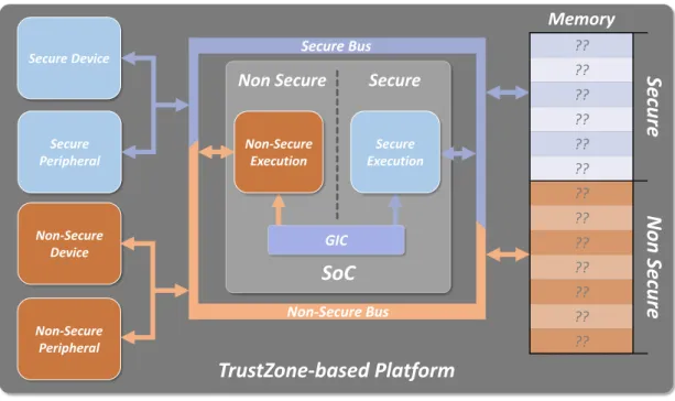
The TrustZone technology divides the processor into two worlds, the Secure (trusted) and Nor-mal (non-trusted) worlds, which subdivide hardware resources and software applications [13; 12]. A processor supporting TrustZone can execute in two states, secure and non-secure, while mem-ory regions, bus accesses, and peripherals can also be assigned to either world [14]. The normal world, being less privileged than the secure, cannot access secure resources, while the opposite is allowed. The TrustZone technology is currently supported in 19 processors with the ARMv7-A, ARMv8-A and ARMv8-M architectures. Among the Cortex-A series, only the Cortex-A5 CPU lacks TrustZone support between the 17 existing processors, meaning this technology is present in roughly 94% of Cortex-A devices [15]. In addiction, a third of the Cortex-M processors are equipped with TrustZone. Although this technology was not designed to be used as a virtualiza-tion tool, the development of TrustZone-assisted hypervisors emerged, as this hardware-based implementation could satisfy the requirements for virtualizing real-time environments [16].
The Lightweight TrustZone-assisted Hypervisor (LTZVisor) [16; 17; 18] is an open-source project developed in-house that takes advantage of TrustZone’s features to better isolate parti-tions, running in a tradition dual-OS configuration — Real-Time Operating System (RTOS) in the secure world and General-Purpose Operating System (GPOS) in the normal world. LTZVisor was originally developed on Xilinx Zynq-7000 devices, which include the ARM Cortex-A9 processor featured with the 32-bit ARMv7-A architecture [19].
selected device for this porting was Xilinx’s Zynq UltraScale+ MPSoC ZCU102 since it resem-bles the already supported platforms — Xilinx Zynq-7000 devices — while also enclosing an ARM Cortex-A53 processor built upon the required ARMv8-A architecture [20]. The board is a hetero-geneous platform that comes with 3 processing units: an ARM Cortex-A53 quad-core Application Processing Unit (APU), an ARM Cortex-R5 dual-core Real-time Processing Unit (RPU), and an ARM Mali-400MP2 Graphics Processing Unit (GPU). This approach merges the flexibility of the three distinct processors with the reconfigurable acceleration provided by programmable logic.
1.2
Goals
With this thesis, it is primarily intended to successfully port LTZVisor to the ARMv8-A tecture, scaling the hypervisor to 64-bit machines. To achieve it, a thorough study of both archi-tectures is required, understanding deeply ARMv7-A and ARMv8-A’s features, such as instruction sets, available registers, interrupts and exception handling, approaches to access memory, and usage of the TrustZone technology. It is also crucial to be able to apply these architectural changes while maintaining — or, if possible, improving — the hypervisor’s behavior, without compromising its core structure.
The porting will allow the hypervisor to be supported on most systems with integrated Trust-Zone, especially ones which include the ARMv7-A and ARMv8-A architectures. A change in ar-chitecture also implies a necessity to adapt the hypervisor to a new platform. The successful adaptation of LTZVisor’s hardware interfaces to the Zynq Ultrascale+ MPSoC ZCU102 board and its components is also an important step towards completing the porting.
1.3
Document Organization
This thesis is organized in six chapters. It starts by mentioning the motivation behind its theme in Chapter 1, going through the proposed goals. Chapter 2 introduces some background concepts necessary to enter into the technical details of this thesis, describing the characteristics of both the ARMv7-A and ARMv8-A architectures. Afterwards, it details some hypervisors with similar features to LTZVisor, namely the use of TrustZone in its core, having support for the ARMv8-A architecture, and the partitioning of the platform’s components. On Chapter 3, LTZVisor is presented and specified, along with its original development platform, Xilinx’s Zynq-7000, and the target platform for this thesis, the Zynq Ultrascale+ MPSoC. Further ahead, Chapter 4 enters into the implementation process of porting LTZVisor to the Zynq Ultrascale+ MPSoC ZCU102 board, describing all the steps taken and the subsequent results. Chapter 5 starts a discussion about the results of the new 64-bit LTZVisor which are evaluated and compared with the results of the original version. At last, Chapter 6 presents the conclusions obtained from this thesis, mainly
the improvements of the 64-bit LTZVisor over the original 32-bit version, its shortcomings, and future additions that may correct those faults.
The realm of virtualized embedded systems belongs to a complex field of technological devel-opment and investigation, brimming with precise concepts and elaborate ideas. As such, it de-mands an objective and thorough clarification of the technologies involved and the nomenclatures used. This chapter is devoted to explaining the fundamental concepts required to conceptualize the theme of this dissertation. Additionally, it covers some similar state of the art projects that resemble this thesis’ work. It starts by describing the evolution of virtualization, grasping its usage on embedded systems, and continues by introducing ARM architecture’s main features and rele-vant technologies like ARM TrustZone, ending with a contextualization of the chosen development platform’s history. The ”Related Work” section showcases several hypervisors with support for ARMv8-A, whilst also exploiting ARM TrustZone technology or partitioning the platform’s hardware components.
2.1
Fundamental Concepts
2.1.1
Virtualization
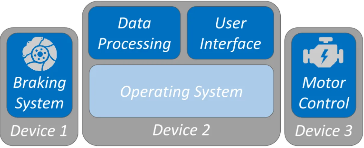
Virtualization technologies surged to improve system requirements that were difficult to as-sess in the 1960s’ computational solutions, mainly the isolation, consolidation, and migration of software workloads [21; 4; 22]. Broadly speaking, virtualization strives to establish an abstracted execution environment which recreates software models as if they were running directly on a physical platform. This environment is carefully monitored to ensure the software model behaves as intended while being abstracted of all system resources it accesses. Traditionally, the software running on the abstracted environment is named Virtual Machine (VM), while the monitoring ac-tivity is done by the Virtual Machine Monitor (VMM), also known as hypervisor. An additional feature of virtualization is the ability to run more than one VM on a single platform, reducing the number of devices necessary for multi-functional solutions, as portrayed in Figure 2.1. Similarly, since the VMs are concealed on an abstraction environment, they are isolated from each other, preventing faults in one VM to compromise other VMs or even the whole system’s integrity.
Device 2
Device 1
Device 3
Operating System
Braking
System
Data
Processing
User
Interface
Motor
Control
(a) Non-Virtualized Automotive System with multiple Devices.
Device 1
Operating System
Virtual Machine Monitor
Braking
System
Motor
Control
Data
Processing
User
Interface
(b) Virtualized Automotive System on a single Device.
Figure 2.1: Addition of Virtualization in an Automotive System. Generally, specific devices were employed for each
application (2.1a). Virtualization allows for distinct functions to operate over the same platform, while maintaining isolation between each VM (2.1b).
It is thanks to these traits that virtualization technologies entered the investigation scene around the world of computation. As physical devices reached a peak of performance that could not be fully satisfied by the adopted applications, there was a switch to the investment on a higher number of functionalities rather than higher levels of performance on a single device [4; 5]. However, increasing the number of applications running on a single platform clogged solutions with vulnerabilities that could jeopardize the whole device. Thus, the abstraction approach of virtualization proved to be a fitting answer, worthy of being applied in server consolidation [22; 23], utility computing [24; 25], network applications [26] or in the multi-operability of operating systems via hypervisors [27; 28; 29].
To comply with the different needs of each application use case and development platforms, various types of virtualization techniques were adopted [28], with emphasis on the following:
• Full Virtualization, where the VMs are completely unaware of the virtual environment
they’re in. The intent of this configuration is to allow unmodified guests to be virtualized, increasing software migration and reducing engineering effort, since they do not need to be adapted to the virtualization environment. Therefore, since the VMs cannot access hardware resources directly, the VMM needs to supply methods that provide a secure interface between the VMs and the physical components they want to use. When the guests try to access the platform’s devices, which they believe are accessing directly, it is trapped to the VMM who then decides whether to accept the access and apply the required operations or to deny it and send a device error to the corresponding VM. Thus, a VMM is the entity responsible for privileged system configurations and to enforce a fully abstracted layer of isolation between each VM and the hardware.
• Para-virtualization, where the VMs recognize the virtual environment they are running
atop. In this configuration, the VMs are adapted to cooperate with the VMM in an at-tempt to improve system performance. While this results in a smaller Trusted Computing Base (TCB) for both the VMM and VMs plus an increase in performance, it requires addi-tional engineering effort in modifying the hosted OSes to be para-virtualized. In fact, while in some cases the changes may be simple and easy to perform, some OSes have little manoeuvrability and adapting them may involve revising deep kernel configurations, up to the point where some OSes are basically impossible to paravirtualize. Consequently, guest OSes that were modified to one para-virtualization solution may not fit on other ap-proaches, requiring additional development efforts and making jeopardizing the original OS architecture possible.
• Hardware-assisted Virtualization, where the hardware platform itself is built to provide
support for virtualization. Traditional approaches to this configuration include a new level of privilege on the Central Processing Unit (CPU) especially to wield a VMM. Virtualization-specific settings are added to the device’s architecture and are restricted to be controlled solely by the new privileged layer. Doing so reduces the VMM’s workload as some VM management operations are assisted by the hardware platform itself. To take advantage of hardware-assisted virtualization, it is necessary to know the platform’s features and to build the virtualization environment with them in mind. This may cause issues when scaling the VMM to other platforms, as the target devices are restricted to those who support the respective hardware-assisted virtualization technology. Similarly, updates to that technology may result in modifying most of the VMM’s core structure instead of just adapting the hardware drivers.
Gradually, virtualization technology was also exploited to be employed in embedded systems. Although it initially provided too much overhead for the small and efficient embedded domain, technologies like hardware-assisted virtualization assisted in reducing those downsides. In fact, understanding and maximizing the platform’s features has always been part of the embedded systems’ developer’s repertoire. Thus, it was possible to adopt virtualization’s laid out layer of abstraction to better isolate partitions with distinct levels of criticality in embedded solutions, such as hard and soft real-time as well as general-purpose applications.
2.1.2
Hypervisor
A hypervisor, or Virtual Machine Monitor (VMM), is a software layer that manages VMs, nor-mally entitled guests, which can range from bare-metal applications to Operating Systems (OSes). Hypervisors normally improve the overall system security by preventing each VM to interfere with the rest of the virtualized system [28; 27]. Hence, hypervisors can be categorized into two types, as shown in Figure 2.2. There are the Type 1 hypervisors - also known as native or bare-metal hypervisors - that run directly above the hardware, and the Type 2 hypervisors - known as hosted hypervisors - that run on top of an OS. Entering into more detail, these two types of hypervisors have the following features:
Hypervisor
Guest OS
Hardware Platform
Guest
App
App App(a) Type-1 or Bare-metal Hypervisor.
Hypervisor
Guest OS
Hardware Platform
OS
Guest
App
App
App
App
App
(b) Type-2 or Hosted Hypervisor.
Figure 2.2: Types of Hypervisors. Type-1 (a) has direct access to the hardware without permission constraints,
while Type-2 is safeguarded by an host OS which can be running additional applications.
• Type-1 or bare-metal hypervisors, are directly deployed on the hardware, which grants
them access to the physical resources available on the device. This implies the hypervisor has the additional effort of thoroughly handling the interfaces between each VM and the system components being used, avoiding any threatening activity the VMs may try to issue upon the hardware. Likewise, accessing the hardware from the hypervisor requires no ad-ditional permission management as the hypervisor belongs to the most privileged system
layer, also reducing overhead when configuring the platform’s resources. Thus, this type of hypervisor is more capable of fulfilling real-time requirements.
• Type-2 or hosted hypervisors, are deployed over an OS that executes and manages
them just like its other applications. Unlike Type-1 hypervisors, where accessing hardware resources can be done directly, this type of hypervisor doesn’t have permission to do so as it belongs to a lower privilege level. The highest privilege level typically runs a full-blown OS, the host, which runs the hypervisor at the same level as its regular applications. As a consequence, while any malfunction originating from the hypervisor cannot harm the hardware directly (as it needs to be handled by the host OS first), the same happens with requests to use the peripherals, either from the VMs or the hypervisor itself. Thus, this approach may slow down the process of configuring the platform resources if the host OS is not prepared accordingly, compromising the use of these hypervisors in real-time scenarios.
Hypervisors are one of the main methods to provide virtualization, being conceived around the end of the 1960s, near the beginning of virtualization’s development [4]. After being thrown off by the surge of multitasking computing during the last decades of the 20th century, hypervisors returned to being a source of attention from 2005 onwards until today. This was due to the concurrent execution of several applications delivered by hypervisors being done in a more secure fashion than a single multitasking OS.
During the initial development stages, hypervisors relied mostly on software virtualization techniques, giving birth to Xen [27] and VMware [28] which were created to be applied in servers and networking applications. More so, as hypervisors entered the embedded systems’ domain, hardware and software developers researched workarounds to increase the efficiency of these monitoring layers.
Hardware-wise, companies like Intel, AMD and ARM developed technologies focused on im-proving performance and decreasing the footprint of software virtualization, making hypervisors much simpler and easier to develop [29]. The first technologies were AMD SVM and Intel’s VT, both designed to improve the support for virtualization techniques in x86 CPUs [10; 9]. Renamed to AMD-V, AMD’s virtualization extensions were not as renowned as Intel’s, which were adopted in many virtualization solutions. To name a few, Intel-VT was exploited in NOVA’s microkernel hypervisor [30], in the Lares architecture capable of secure, active monitoring in a virtualized environment [31], and by IBM in a nested virtualization project named Turtles [32].
Virtualization surged in embedded systems when ARM released their own virtualization ex-tensions (VE) on their architectures, starting with the Cortex-A15 core [11; 15]. The addition of hardware-assisted virtualization technology in ARM platforms lead to the surge of full system virtu-alization solutions with low overhead, namely the KVM/ARM [33] and the CASL hypervisor [34]. As these extensions became a staple in ARM’s latest architectures, they were employed together
with other architectural features to properly design low-level hypervisors that complied with the embedded systems’ requirements. In fact, a wave of hypervisors based on ARM’s security ex-tensions (TrustZone) is emerging [12], which are mentioned in Section 2.2 as this dissertation’s related work.
Due to the relevance of hardware-assisted virtualization technologies on virtualized embed-ded systems, the design of hypervisors started to gradually rely more on the hardware features than on software-based virtualization methods, thus requiring deeper knowledge of the system’s architectural characteristics. Hence, it is also fundamental to elaborate on the constraints of working on the architecture of an embedded system. Following the theme of this dissertation, the architecture specified will be the one nurtured by ARM, a powerhouse on the industry of mi-croprocessor development [35] and whose latest high-performance architectures belong in this thesis’ highlight.
2.1.3
ARM Architecture
One of the most renowned product lines of the embedded industry is the ARM line of micro-processors, which are currently employed in billions of sold products that range from consumer devices to critical vehicle systems. In order to embrace such a variety of scenarios, ARM provides numerous processor models, each with a distinct purpose, but all of them built over the same architectural model [36]. While the fundamentals of ARM’s architecture have suffered minimal changes, it has adapted over the years according to the trending technological advances.
ARM’s products follow a Reduced Instruction Set Computer (RISC) architecture, marked by a small but more generic instruction set where each instruction is executed during a single high-speed clock cycle [36]. With a simpler instruction set, a RISC architecture exerts little effort on the processor, increasing the burden on the compiler. It contrasts with the Complex Instruction Set Computer (CISC) architecture that provides a more extensive and complex instruction set with a higher strain on the processor instead of the compiler. A device with a RISC design is expected to have a large and uniform register file, load/store memory access methods and simple addressing modes, where data processing operations avoid memory accesses and use the general-purpose registers [37; 38; 35].
Although ARM consents with these features, it doesn’t strictly obey RISC’s approach, person-alizing its architecture to a design that fits the embedded systems’ field [35; 36]. The principles that differentiate ARM’s architecture from a pure RISC design are:
• Variable cycle execution - Some ARM instructions, such as load/store-multiple, do
not execute during a single cycle, reducing overall code density when multiple memory accesses are performed, like on the entry and exit points of functions;
• Inline barrel shifter - This hardware component is able to perform a shift on one of the
input registers before it is used by an instruction, accelerating the register manipulation to the hardware, hence reducing the payload on the processor;
• Inclusion of Thumb instruction set - Thumb is a 16-bit instruction set that is used
side-by-side with ARM’s 32-bit instruction set. The developer can assign the processor to either of the instruction sets and change between them during execution. This addition upgrades code density by around 30% when compared to using solely 32-bit fixed-length instructions;
• Conditional execution - Applying conditional execution to all of its instructions achieves
faster and lighter behaviors while reducing the occurrence of branch instructions;
• Enhanced instructions - The standard ARM Instruction Set Architecture (ISA) provides
Digital Signal Processing (DSP) operations via enhanced instructions. Since DSP services are highly requested in embedded applications, having the option to run them directly on the processor is more efficient than relying on a CPU plus digital-signal processor combination.
As verified above, ARM prepares its processors specifically to the embedded domain, making the necessary tweaks to provide an efficient solution that complies with the size, weight, power, and cost (SWaP-C) requirements of modern devices.
ARM has had various versions of its architecture since it was first developed, as indicated in Table 2.1. Each version is represented by a number suffixed to the ”ARMv” tag, e.g. ARMv6. With each version, that number is incremented, where the most recent architecture is ARMv8. Out of these 8 versions, the first 3 are already completely obsolete [38; 35]. Still, the currently most
Table 2.1: List of ARM Architectures and respective variants (obsolete variants are marked with an *). The Cortex
family were first implemented on ARMv6 but only became prominent on the ARMv7 and ARMv8 paradigms.
Architecture Variants
Cortex-A Cortex-R Cortex-M
ARMv1 ARM1*
ARMv2 ARM2* ; ARM3*
ARMv3 ARM6* ; ARM7*
ARMv4 ARM7T ; ARM8 ; ARM9T
ARMv5TE ARM7EJ ; ARM9E ; ARM10E
ARMv6 ARM11
M0/0+/1
ARMv7 A5/7/8/9/15/17 R4/5/7/8 M3/4/7
prominent architectures are ARMv7 and ARMv8, which have a much wider reach of applications due to the Cortex families.
ARM’s processors are also discerned by families which reflect the design of their core. They are named similarly to the architecture versions, with suffixed numbers but without the ”v” char-acter in the middle, starting on the ARM1 family until the ARM11 family that featured the ARMv6 architecture [36]. From there onwards, upon reaching the 7thversion of its architecture, a need to
develop more specialized products surged, which pushed ARM into renovating their systems. The next step was taken when ARM established their processors with the ”Cortex” tag, categorizing them and the respective architectures in 3 profiles:
• Application profile, depicted by the -A suffix (ARMv7-A, Cortex-A) and supporting a
vir-tual memory system architecture (VMSA) based on a memory management unit (MMU). This profile was specifically designed to be used on high-performance processors, capable of handling virtualized environments and full-fledged OSes. Supports both the ARM and Thumb instruction sets;
• Real-time profile, depicted by the -R suffix (ARMv7-R, Cortex-R) and supporting a protected
memory system architecture (PMSA) based on a memory protection unit (MPU). It was devised to run deterministic systems with low interrupt latency. Supports both the ARM and Thumb instruction sets;
• Microcontroller profile, depicted by the -M suffix (ARMv7-M, Cortex-M) and lacking a MMU.
Provides a new system-level programmers’ model designed directly towards embedded systems with hard deterministic timing and power, performance and area constraints. Solely supports a variant of the Thumb instruction set [39].
These profiles offer the ARM portfolio a much more widespread range of applications and an organized structure for future progress. Still, this remodelling was not enough to cope with the challenge of 64-bit systems, which was only targeted by ARMv8-A. This architecture reformed the traditional features of ARM’s architecture to arrange the processors for both 64-bit and 32-bit exe-cution on the same core. Out of many changes, which are explained with higher detail in Section 2.1.3.2, ARMv8-A disposes of the co-processors and the instructions that access them, removes the traditional load/store multiple instructions and no longer supports the Thumb instruction set [37].
Beyond all of the released architectural versions, ARM has also invested in supplementary technologies that complement their devices with particular features, useful for specific applica-tions or to aid the development of processes that were complex to idealize and implement using legacy technology. Some of those technologies were incorporated on architectures over the years (Figure 2.3), including the NEON technology, DSP extensions, support for Floating Point oper-ations, virtualization extensions (ARM VE), and the TrustZone security extensions [41], which is
Figure 2.3: Cumulative features of the latest ARM architectures (taken from [40]). As new architectures were
introduced, the features of previous architectures were kept throughout their evolution.
a crucial trait for the type of hypervisors this thesis is based on. I will now begin to delve into the central architectures for the porting of LTZVisor, mainly the original ARMv7-A and the target ARMv8-A, concluding with an specification of the TrustZone technology.
2.1.3.1 ARMv7-A
ARMv7 is a 32-bit architecture that follows ARM’s legacy in the development of processors. This architecture was a huge contributor to widen ARM’s horizons in its products by introducing the architecture profiles: Application (A), Real-Time (R), and Microcontroller (M). This thesis’ project focuses solely on the Application profile, which is aimed at high-performance processors and supports a VMSA based on a MMU [38]. ARMv7-A inherits both the ARM (A32) and Thumb (T32) instruction sets (along with the ability to interwork between them), DSP extensions, and multiprocessing instructions from previous architectures, while also introducing new features such as NEON technology. Finally, ARMv7-A incorporates the first versions of the General Interrupt Controller (GIC), which was designed to manage interrupts in a system.
2.1.3.1.1 Processor Modes
An ARMv7-A CPU can execute in 9 different modes, which represent various states of exe-cution. These modes are: User (USR), System (SYS), Supervisor (SVC), Abort (ABT), Undefined (UND), FIQ (FIQ), IRQ (IRQ), Hypervisor (HYP) and Monitor (MON) [38]. The hypervisor mode is only available in devices that integrate ARM’s Virtualization Extensions, while the monitor mode
USR mode USR mode
SVC, ABT, IRQ, FIQ, UND, SYS
modes HYP mode
Non-Secure
Secure
PL0
PL2
PL1
SVC, ABT, IRQ, FIQ, UND, SYSmodes
MON mode
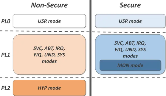
Figure 2.4: ARMv7 processor modes and the corresponding Privilege Levels. The concept of orthogonality between
processor modes and execution states can be verified, as most processor modes exist on both the secure and normal worlds, except the hypervisor mode that is always non-secure and the monitor mode which is always secure. only exists when the TrustZone security extensions are implemented. The monitor mode is al-ways secure, while the Hypervisor mode only exists in the normal world. These processor modes are linked with the Privilege Levels (PLs), which indicate the permission status of each proces-sor mode. Figure 2.4 showcases how the nine procesproces-sor modes fit into the three PLs available in ARMv7-A. Non-secure execution is always considered less privileged than secure execution, independently of privilege level, as some registers and instructions can only be accessed and performed by secure execution. Thus, even if the hypervisor mode belongs in the highest PL, it is considered to be less privileged than the processor modes located in secure PL1. The privilege levels have the following properties:
• PL0 - With the fewest amount of permissions, it is associated with user-level execution,
encompassing solely the user (usr) mode. It is considered the unprivileged mode which cannot access system configuration registers or privileged memory.
• PL1 - In this level, execution can access basically all features from the architecture, except
for the ones added by PL2. This PL includes 7 processor modes: system, supervisor, abort, IRQ, FIQ, undefined and monitor (secure world only). Software executing at those modes is considered to be privileged and is able to access both unprivileged and privileged resources.
• PL2 - It is only associated with the hypervisor mode, which is also a privileged mode. PL2
and the hypervisor mode were added to the ARMv7-A architecture as part of ARM’s Virtual-ization Extensions with the intuit of isolating the configuration the virtualVirtual-ization extensions’
features in a single higher privilege mode.
Execution can switch between modes whenever an exception or interrupt occurs and it’s trapped on the respective mode. However, it is also possible to manually switch to another processor mode by using one of three special instructions: the Supervisor Call (SVC), Hypervisor Call (HVC), and Secure Monitor Call (SMC). Each of this instructions is trapped to the supervisor, hypervisor, and/or monitor modes respectively, and can only be issued when the execution is running on the same PL as the destination mode or on the immediately lower PL. Therefore, SVC and SMC can be used on all modes except the hypervisor mode, which is in PL2. On the other hand, HVC can be used on all modes located in PL1, but not on the User mode located in PL0, as doing so would issue a jump from PL0 to PL2, which is not directly allowed in ARMv7-A. The HVC requires a special setup as it only works properly if issued on the normal world (SCR.NS bit must be active) and when the instruction is activated by setting the SCR.HCE bit, which is cleared on system reset.
2.1.3.1.2 Registers
ARMv7-A includes thirteen 32-bit general-purpose registers (R0 to R12), a Stack Pointer (SP), a Link Register (LR), and a Program Counter (PC), which are defined as R13, R14, and R15 respectively. These last three registers are designated special-purpose registers that, such as the Saved Program Status Register (SPSR), have distinct copies for each of the processor modes as Figure 2.5 showcases. These copies are denoted as banked copies, implying that using the common register token . Registers that follow this behaviour are called banked registers, and can have copies for every processor mode .
The System mode has access to the same registers as the User mode but from PL1 instead of PL0. Along with the hypervisor mode, these three modes share the same LR, while the hypervisor mode adds the Exception Link Register (ELR_hyp) to indicate the returning address when leaving PL2 via the ERET instruction. When switching processor modes, the Program Status Registers are modified as they save the execution status. ARMv7-A provides an application and a system view of these registers, namely the Application Program Status Register (APSR) and the Current Program Status Register (CPSR). Both of them have the same purpose, although the CPSR adds extra system level information (Figure 2.6). The SPSRs represent asynchronous copies of the CPSR that are saved whenever an exception occurs to the respective mode. As Figure 2.5 shows, there is a SPSR for each processor mode except the User mode (which can’t handle exceptions as it belongs to the unprivileged PL0), and the System mode (which is never a target for an exception).
Apart from the core registers, ARMv7-A has a large bundle of system control registers, de-signed to configure system-level settings, such as TrustZone, cache, vector table, and VMSA con-figurations. Not all of these registers exist in every version of ARMv7-A, depending on whether it
includes Security and/or Virtualization Extensions. System control registers cannot be read/writ-ten by PL0 execution since that is only possible by accessing the CP15 and CP14 coprocessors. In a device with Security Extensions, system control registers can have different behaviours:
• Banked registers, which have two separate copies, one for the secure world and another
for the normal world. Just a few of the CP15 registers can be banked (e.g. ACTLR, SCTLR, VBAR).
• Restricted access registers, which are only present in the secure world. Attempts
to access these registers from the normal world are not permitted (e.g. SCR, NSACR, MVBAR).
• Configurable access registers, which can be configured by secure software to be
accessed by both worlds or only by the secure world. The NSACR is the register responsible for such configuration (e.g. FPSCR, FPEXC, MVFRs).
• PL2-mode registers, which are intended to be used in PL2. They can be banked CP15
read/write or write-only and shared CP15, responsible for configuring the Hypervisor mode interfaces and execute PL2-related operations.
ARMv8 Registers
ARM DEN0024A Copyright © 2015 ARM. All rights reserved. 4-14 ID050815 Non-Confidential
Figure 4-7 The ARMv7 register set showing banked registers Banking is used in ARMv7 to reduce the latency for exceptions. However, this also means that of a considerable number of possible registers, fewer than half can be used at any one time. In contrast, the AArch64 execution state has 31 × 64-bit general-purpose registers accessible at all times and in all Exception levels. A change in execution state between AArch64 and AArch32 means that the AArch64 registers must necessarily map onto the AArch32 (ARMv7) register set. This mapping is shown in Figure 4-8 on page 4-15.
The upper 32 bits of the AArch64 registers are inaccessible when executing in AArch32. If the processor is operating in AArch32 state, it uses the 32-bit W registers, which are equivalent to the 32-bit ARMv7 registers.
AArch32 maps the banked registers to AArch64 registers that would otherwise be inaccessible.
(A/C)PSR
User FIQ IRQ ABT SVC UND
R0 R1 R2 R3 R4 R5 R6 R7 R8 R9 R10 R11 R12 R13(sp) R14(lr) R15(pc) R0 R1 R2 R3 R4 R5 R6 R7 R8_fiq R9_fiq R10_fiq R11_fiq R12_fiq SP_fiq LR_fiq R15(pc) R0 R1 R2 R3 R4 R5 R6 R7 R8 R9 R10 R11 R12 SP_irq LR_irq R15(pc) R0 R1 R2 R3 R4 R5 R6 R7 R8 R9 R10 R11 R12 SP_abt LR_abt R15(pc) R0 R1 R2 R3 R4 R5 R6 R7 R8 R9 R10 R11 R12 SP_svc LR_svc R15(pc) R0 R1 R2 R3 R4 R5 R6 R7 R8 R9 R10 R11 R12 SP_und LR_und R15(pc) SPSR_fiq CPSR SPSR_irq CPSR SPSR_abt CPSR SPSR_svc CPSR SPSR_und CPSR Banked CPSR R0 R1 R2 R3 R4 R5 R6 R7 R8 R9 R10 R11 R12 R13(sp) R14(lr) R15(pc)
Sys MON HYP
R0 R1 R2 R3 R4 R5 R6 R7 R8 R9 R10 R11 R12 SP_mon LR_mon R15(pc) R0 R1 R2 R3 R4 R5 R6 R7 R8 R9 R10 R11 R12 SP_hyp LR_hyp R15(pc) SPSR_mon CPSR SPSR_hyp CPSR ELR_hyp
Figure 2.5: Core Registers of the ARMv7-A Architecture (taken from [40]). They are mapped through the processor
Figure 2.6: ARMv7-A APSR, CPSR and SPSR formats (adapted from [38]). The CPSR and SPSR contain more
detailed info, such as the processor mode (M[4.0])and exceptions mask flags for Aborts (A), IRQs (I), and FIQs (F).
• Common registers, which belong to both Secure and normal worlds, maintaining its
values during a domain switch. Some CP15 registers fall in this category (e.g. MIDR, CTR, MPIDR) along with all CP14 registers (debug, trace and execution environment control registers).
Accessing the CP15 and CP14 coprocessors may also issue some system control operations, which are not part of the supported instruction set.
2.1.3.1.3 Instruction Sets
ARMv7-A supports two instruction sets, the 32-bit ARM instruction set (A32) and the 16-bit or 32-bit Thumb instruction set (T32). Thumb also provides 16-bit instructions, which can provide more efficient execution than 32-bit instructions, especially if the required operations have low-complexity [38]. Both instruction sets are compatible with each other, so software can interwork between the ARM and Thumb instruction sets at any time with no overhead when swapping between the two. It is possible to change from one state to another using the BX, BLX, LDR or LDM instructions, which are available in both sets. The A32 instruction set contains additional instructions to swap to the Thumb-based execution.
Overall, ARMv7-A offers instructions capable of performing arithmetic, logical and other data-processing operations on the core registers. There are three ways to access the coprocessors and activate their features: initiating a coprocessor data-processing operation (CDP and CDP2 instructions), moving core registers to and from the coprocessor registers (MRC and MCR types of instructions) and by loading or storing the values of the coprocessor registers (LDC and STC instructions).
Most coprocessors have vendor-specific features (CP0-7) or were reserved for future use by ARM (CP8, CP9, CP12, and CP13). Excluding those, the CP10 and CP11 can be used to issue floating-point and Advanced SIMD operations and CP14 to handle debug, trace and Thumb Execution Environment operations. That leaves the CP15 coprocessor which is the one with the most varied functionalities. Table 2.2 indicates the features that each primary coprocessor offers
Table 2.2: Organization of CP15 registers and available operations (adapted from [38]). The CP15 is organized in
16 primary coprocessor registers (CRn), which can have different functions according to 2 opcodes (opc1 and opc2) and a secondary coprocessor register (CRm).
CRn opc1 CRm opc2 Function
c0 0-2 c0-c7 0-7 ID registers
c1 0,4 c0,c1 0-7 System Control registers
c2 0,4 c0,c1 0-2 Memory Protection and Control registers c3 0 c0 0 Memory Protection and Control registers
c4 - - - Not used
c5 0,4 c0,c1 0,1 Memory System Fault registers c6 0,4 c0 0,2,4 Memory System Fault registers
c7 0,4 Various Various Cache Maintenance, Address Translations c8 0,4 Various Various TLB Maintenance Operations
c9 0-7 Various 0-7 Performance Monitors and Maintenance c10 0-7 Various 0-7 Memory Mapping and TLB Operations c11 0-7 c0-c8,c15 0-7 DMA Operations for TCM access c12 0,4 c0,c1 0,1 Security Extensions (if implemented) c13 0,4 c0 0-4 Process, Context and Thread ID registers c14 0-7 c0-c15 0-7 Generic Timer registers (if implemented) c15 0-7 c0-c15 0-7 IMPLEMENTATION DEFINED
to the architecture, including control and configuration operations on system-level functionalities, confirming the importance of CP15 on an embedded design like LTZVisor. The functionalities of the CP15 coprocessor operations may vary according to the implementation of each ARMv7-A processor. Thus, further specification of the CP15 coprocessor operations can be found in the target CPU’s technical reference manual (p.e. Cortex-A9 [42]).
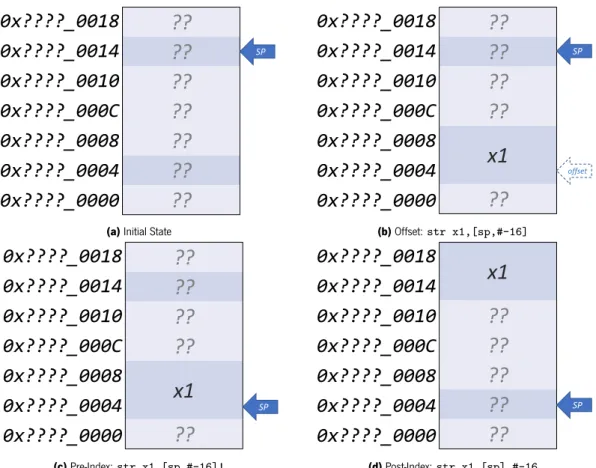
Proceeding with ARMv7-A instructions, it is known that ARM’s architecture traditionally applies load/store mechanisms to transfer register data from and to memory (see Section 2.1.3). Those load/store mechanisms are supported by various instructions that differ from each other on the size of each transferred element and their number, including the load/store multiple instructions (LDM and STM). Loading and storing can be used with the SP as the destination register, acting as PUSH or POP stack management instructions, which can also write and read multiple registers with a single PUSH or POP instruction.
Additionally, ARMv7-A provides flexible conditional execution by offering a bunch of branching instructions with many scenarios in mind. The B instruction is the most basic branch, which jumps to the indicated address, with a range of± 256 bytes when using 16-bit Thumb branching or± 1MB when using A32 or 32-bit Thumb branch instructions. Branching can also be done by writing an address directly to the PC. Every branch can be assisted by four conditional flags — Zero (Z), Carry (C), Negative (N) and Overflow (V) — that indicate the conditional state of execution
Table 2.3: ARMv7-A available conditions and conditional flag combinations (adapted from [38]). By analysing the
binary state of the four conditional flags, an ARMv7-A processor is able to determine a specific conditional scenario of execution.
Condition Meaning Flags
0000 (EQ) Equal Z==1
0001 (NE) Not Equal Z==0
0010 (CS) Carry Set C==1
0011 (CC) Carry Clear C==0
0100 (MI) Minus, Negative N==1
0101 (PL) Plus, Positive or Zero N==0
0110 (VS) Overflow V==1
0111 (VC) No Overflow V==0
1000 (HI) Unsigned Higher C==1 and Z==0 1001 (LS) Unsigned Lower or Same C==0 and Z==1 1010 (GE) Signed Greater Than or Equal N==V
1011 (LT) Signed Less Than N!=V
1100 (GT) Signed Greater Than Z==0 and N==V 1101 (LE) Signed Less Than or Equal Z==1 or N!=V 1110 (None) Always (unconditional) Any
through binary combinations, as seen in Table 2.3. These flags are altered when comparative instructions (CMN and CMP) or certain data processing instructions ending with the character ”S” (MOVS, ADDS and SUBS) are executed. Furthermore, the conditional mnemonics shown can be suffixed to another instruction (for example, ”ADDNE”) to indicate that the typed instruction is only executed if the specified condition is true, providing flexible and responsive conditional behaviours.
Furthermore, ARMv7-A offers system barrier instructions, that order and synchronize ac-cesses to memory (ISB, DSB, and DMB), processor hints (YIELD and DBG) and exception handling instructions, either to generate exceptions (SVC, HVC, and SMC) or to return from them (ERET). 2.1.3.1.4 Exception Handling
ARMv7-A has five types of exceptions: reset, interrupts, memory system aborts, undefined instructions, and system calls [38]. These types can be broken up into nine exceptions:
• Reset goes back to the starting point of execution after stopping it beforehand. Upon reset,
the processor starts in secure Supervisor mode (PL1). The starting point of execution can be at the low or high reset vector address (0x00000000 or 0xFFFF0000 respectively), depending on the reset value of the SCTLR.V bit;
• IRQ, triggered by an IRQ interrupt, executes the handler of the respective interrupt.
When-ever an IRQ exception is taken, the processor traps, by default, into the IRQ mode (PL1), but can also trap to the hypervisor (PL2) or monitor (PL1) modes depending on system configurations;
• FIQ, which occurs once a FIQ interrupt is triggered. It traps execution to the FIQ mode
(PL1) in order to execute the handler of the respective FIQ interrupt. Similarly to the IRQ exceptions, the processor may trap to the hypervisor (PL2) or monitor (PL1) modes depending on system configurations;
• Data Abort exceptions are prompted when erroneous memory accesses are performed,
whether in data reads or writes, instruction fetches or translation table accesses. They are handled in abort mode (PL1) but can be configured to be handled in hypervisor (PL2) or monitor mode (PL1).
• Prefetch Abort happens when a fetched instruction is located on memory that is
inac-cessible by current execution, therefore the fetch is aborted and the exception triggers. It is handled on the abort mode (PL1) but can be configured to be handled in hypervisor (PL2) or monitor mode (PL1).
• Undefined Instruction occurs whenever an instruction with undefined or invalid
be-haviour is attempted to be executed, such as disabled coprocessor operations or unimple-mented instructions. The handler to these exceptions runs in undefined mode (PL1), but can also be handled in the hypervisor mode (PL2);
• Supervisor Call is triggered via the SVC instruction, which is used to enter the supervisor
mode (PL1), normally from the user mode (PL0);
• Hypervisor Call requests functionalities unique to the Hypervisor mode (PL2), normally
related to the reconfiguration of virtualization extensions’ functionalities. This exception is triggered by issuing the HVC instruction when the virtualization extensions are implemented and from a processor mode with PL1 privilege running in the non-secure state;
• Secure Monitor Call is an exception triggered by the SMC instruction that is handled
in monitor mode (PL1). It is frequently used to request operations that are only permitted from the secure monitor layer, such as transitioning from one execution state to the other. The handlers of these exceptions are named exception vectors and are located in unique addresses. They are arranged in sets of 8 entries, where each set is known as a vector table. There are four vector tables: one for the hypervisor mode, one for the monitor mode, and one for each of the PL1 worlds, the secure and the normal. Table 2.4 shows the contents of those
Table 2.4: Arrangement of Exception Vector Tables in ARMv7-A (adapted from [38]). The entries have 4 bytes of
memory between themselves, having room for solely a single instruction.
Offset Hypervisor Monitor Secure Non-Secure
0x00 - - Reset
-0x04 Undefined - Undefined Undefined
0x08 HVC SMC SVC SVC
0x0C Prefetch Abort Prefetch Abort Prefetch Abort Prefetch Abort 0x10 Data Abort Data Abort Data Abort Data Abort
0x14 Hyp Trap - -
-0x18 IRQ IRQ IRQ IRQ
0x1C FIQ FIQ FIQ FIQ
vector tables and how they’re arranged. It can be seen that each handler has room for a single instruction before the offset of the next handler, almost obligating the use of subroutine branches on the vector table’s memory space. The base address of each of the vector tables is contained on the following system registers: HVBAR for the hypervisor, MVBAR for the monitor and VBAR for both the secure and non-secure vector tables. The later being a banked register, it contains the address of the vector table related to the current execution domain and swaps its value whenever there is a world-switch. It can also be confirmed in Table 2.4 that the program reset starts in the Secure PL1 and that the monitor mode has permission to execute any instruction, lacking an Undefined Instruction handler. The Hyp trap exception indicates the entry point of the Hypervisor mode.
2.1.3.2 ARMv8-A
ARMv8-A is the most recent ARM architecture, introducing its processors to the 64-bit realm. It presents major changes to the traditional ARM features while maintaining a high level of con-sistency with its previous versions [37]. While all variants of this architecture include TrustZone, there are extensions to the ARMv8-A architecture that bring even more features, such as allowing the Exception Level 2 (EL2) to exist on the Secure World (available in ARMv8.4-A) [37]. Since the CPU enclosed in this project’s development platform supports the ARMv8.0 version of the archi-tecture, it does not include any of those extensions. Hence, they will not be further described as they do not belong in the range of this dissertation’s investigation. The most interesting feature in ARMv8-A is the introduction of two distinct execution states:
• AArch32, which envisions to mimic the 32-bit A environment, allowing for
ARMv7-A compatible software to be compiled and run even in systems supporting ARMv7-ARMv8-ARMv7-A;
• AArch64, bringing the innovative features of the ARMv8-A architecture, such as a 64-bit
![Figure 2.3: Cumulative features of the latest ARM architectures (taken from [40]). As new architectures were introduced, the features of previous architectures were kept throughout their evolution.](https://thumb-eu.123doks.com/thumbv2/123dok_br/17234245.787147/32.892.165.783.131.498/cumulative-features-architectures-architectures-introduced-features-architectures-evolution.webp)
![Figure 2.6: ARMv7-A APSR, CPSR and SPSR formats (adapted from [38]). The CPSR and SPSR contain more detailed info, such as the processor mode (M[4.0])and exceptions mask flags for Aborts (A), IRQs (I), and FIQs (F).](https://thumb-eu.123doks.com/thumbv2/123dok_br/17234245.787147/36.892.171.780.129.295/figure-formats-adapted-contain-detailed-processor-exceptions-aborts.webp)
![Figure 2.7: ARMv8-A Exception Levels (adapted from [40]). The secure monitor mode is isolated from the rest of EL1 modes, inhabiting the most privileged level of execution EL3](https://thumb-eu.123doks.com/thumbv2/123dok_br/17234245.787147/42.892.163.780.134.468/figure-exception-levels-adapted-isolated-inhabiting-privileged-execution.webp)
![Figure 2.11: GICv1 distributor and CPU interface blocks (adapted from [43]). Interrupt signals enter the distributor which routes them to the correct CPU](https://thumb-eu.123doks.com/thumbv2/123dok_br/17234245.787147/50.892.178.783.418.1004/figure-distributor-interface-adapted-interrupt-signals-distributor-correct.webp)
![Figure 2.13: Jailhouse’s System Overview (adapted from [54]. After the root cell launches Jailhouse, it lets the hy- hy-pervisor partition the system’s resources, supplying them to other cells](https://thumb-eu.123doks.com/thumbv2/123dok_br/17234245.787147/55.892.172.781.129.581/jailhouse-overview-launches-jailhouse-pervisor-partition-resources-supplying.webp)
![Figure 2.14: VOSYSmonitor System Overview (adapted from [55]). Structured similarly to LTZVisor, VOSYSmonitor features mixed criticality guests, with a secure real-time VM and full-fledged software on the unprivileged world.](https://thumb-eu.123doks.com/thumbv2/123dok_br/17234245.787147/57.892.170.783.134.613/vosysmonitor-overview-structured-similarly-ltzvisor-vosysmonitor-criticality-unprivileged.webp)
