ABSTRACT
The present paper presents a comparison of the seismic provisions of the three seismic design codes, namely the Philippine code (National Structural Code of the Philippines or NSCP2010), the European code (Eurocode 8 or EC8), and American code (2009 International Building Code or 2009 IBC), to the most common ordinary residential building of standard occupancy. Two regular and irregular reinforced concrete (RC) frames were analysed and compared for four storey and eight storey buildings. The response spectrum function of NSCP 2010 was considered for the horizontal load action with different load combinations. Response spectrum analysis was performed using SAP2000 software package. Five representative columns for each RC frames were analyzed and based from the results of column axial load - bending moment interaction diagrams, EC8 was found to be conservative as compared to NSCP 2010 and 2009 IBC. The conclusion is that for the design and analysis of ordinary RC residential building with certain irregularity, EC8 provisions were considered to be safer.
Keywords: seismic design, building codes, response spectrum, reinforced concrete (RC)
frames, interaction diagrams, steel reinforcements, steel ratio
INTRODUCTION
Earthquakes occurring recently in highly populated zones have shown that existing buildings constructed without appropriate seismic resisting characteristics constitute the main source of risks and are the cause of most of the casualties (Varum, 2003). The interest in gaining better understanding of the seismic behaviour of reinforced concrete building structures has grown in the past two decades. Damage reports on past earthquakes have indicated that one major cause of failure in RC framed structures is the torsional response of the buildings, induced by the earthquake and/or by the structural irregularities and characteristics. Seismic provisions typically specify criteria for the design and construction of new structures subjected to earthquake ground motions with three goals: (1) minimize the hazard to life from all structures, (2) increase the expected performance of structures having a substantial public hazard due to occupancy or use, and (3) improve the capability of essential facilities to function after an earthquake (Taranath, 2010). Provisions and assumptions for the design of (RC) frames with structural irregularity appear in majority of the international standards of concrete design. Recently enforced seismic codes, such as NSCP, EUROCODE, and IBC have motivated several research activities in each regional seismic code.
PAPER REF: 2955
COMPARATIVE ANALYSIS OF RC IRREGULAR BUILDINGS
DESIGNED ACCORDING TO DIFFERENT SEISMIC
DESIGN CODES
Please leave this line blank
Jaime Landingin1(*), Hugo Rodrigues2, Humberto Varum3, António Arêde4, Aníbal Costa5
1,2,3,5
Department of Civil Engineering, University of Aveiro, Portugal
4
Department of Civil Engineering, University of Porto, Portugal
(*)
This paper, firstly, presents a review of the revisions and history of well-known international standards. The chosen standards for this study are the Philippine code (NSCP 2010), European code (European Standard, Eurocode 8), and American code (2009 IBC). Secondly, a comparative analysis was performed in terms of reinforcement requirements in representative columns as per the three seismic codes.
NSCP2010
The National Structural Code of the Philippines (NSCP) has been the primary design code that provides guidance to civil and structural engineers on the design and evaluation of buildings, and any other structures since its 1st Edition in 1972. Table 1 shows the brief history of the NSCP (ASEP, 2010).
Table 1 Selected events in the history of building codes in the Philippines
Edition Official Title
1st National Structural Code of Buildings (NSCB1972) 2nd National Structural Code of Buildings (NSCB 1981) 3rd National Structural Code of Buildings (NSCB 1987) 4th National Structural Code of the Philippines (NSCP 1992) 5th National Structural Code of the Philippines (NSCP 2001) 6th National structural Code of the Philippines (NSCP 2010)
The latest edition of the NSCP has been historically based on the Uniform Building Code (UBC) 1997 of the USA. Furthermore, UBC 1997 was the first building code that included seismic design provisions that were significantly based on seismic data collected in the early 1990´s. The code specifies that the design response spectrum to be used in the analysis was based on factors such as soil profile and seismic zone based on fault proximity. The NSCP 2010 adopted the provisions of UBC for earthquake loadings and made 2009 IBC and ACI318-08M as a reference (ASEP, 2010).
EC8
In Europe, Part 1 of Eurocode 8 (CEN 2004a) was published by the European Committee for Standardisation to become the first in history of European Standard for seismic design of new buildings, complementary to the other EN Eurocodes. It was followed in June 2005 by Part 3 of Eurocode 8 (CEN 2005a), for seismic assessment and retrofitting of existing buildings. The 31 member countries in CEN have since then published these European Standards as their own National Standards, together with their National Annexes. These Annexes state the national choices for the so-called “Nationally Determined Parameters”, devised to provide the flexibility required for the application of Eurocode 8 in a whole continent with diverse engineering traditions and seismicity. Until March 2010 national design standards will be used in parallel with Eurocode 8, but by March 2010 national design standards that conflict in any aspect with any EN-Eurocode should be withdrawn (Fardis, 2009).
The vast majority of buildings, in earthquake prone areas in Europe, constructed before the 1980´s are seismic deficient in terms of our current understanding. Furthermore, a significant number of existing RC building structures were constructed before the 70´s, with plain reinforcing bars, prior to the enforcement of the modern seismic-oriented design philosophies (Melo, 2011). In fact, in some European countries until the 1960´s no specific seismic design provisions were included in building codes and, from that period on, only seismic equivalent lateral loading were considered in building design. Provisions for the design and detailing of members and structures resembling those of modern codes only appeared in European national codes in the 1980´s (e.g., Portuguese design code - RSA [1983]; European design code - Eurocode 8 (Rodrigues, 2010).
The very recent earthquakes in Europe (e.g. Bucharest, Romania, 1977; Montenegro, Yugoslavia, 1979; Azores, Portugal, 1980; Campania, Italy, 1980; Kalamata, Greece, 1986; Umbria/Marche, Italy, 1997; Azores, Portugal, 1998; Kocaeli, Turkey, 1999; Athens, Greece, 1999; Molise, Italy, 2002 and 2009; Spain, 2011) confirm and highlight that also Europe may suffer from the vulnerability of the existing building stock (Varum, 2003). Majorities of the countries mention adopted and implemented European Standards in the design and analysis of their structures.
IBC2009
The earliest model code in the United States (US) was the National Building Code recommended by the National Board of Fire Underwriters, published in 1905 in response to fire insurance losses in the Great Baltimore Fire of 1904. Furthermore in 1927, the Pacific Coast Building Officials promulgated the Pacific Coast Building Code, which later became the Uniform Building Code. The organization of this code differed from that of the National
Building Code in that it ranked occupancies by life risk and linked fire safety criteria to
specific occupancies. The code included provisions for exiting and control of material finishes. In addition, this code contained numerous structural provisions organized by building material type.
The Uniform Building Code (UBC) was widely used west of the Mississippi River until the adoption of the International Building Code in 2000. The National Building Code was promulgated by the insurance industry. It was the basis for most local and state codes until late in the last century (Green, 2012). To date UBC is also the model or reference code for developing countries around the world.
The Southern Building Code, later the Southern Standard Building Code (SBC), was first published by the Southern Building Code Congress in 1945. The Basic Building Code, published by the Building Officials of America (now the Building Officials and Code Administrators International) (BOCA), was first published in 1950. It served the Midwest and New England regions. BOCA later obtained the right to use the title National Building Code. Some editions of the code are called the BOCA/National Building Code. These organizations that published the three model codes were membership organizations with members from the building industry, the building regulatory community, and the public. Originally, only building officials could vote on code changes. However, the code change process was an open process involving submittals, hearings with industry and public involvement, and open advisory voting by the membership. The model building codes were updated on a three-year cycle (Green, 2012).
Beginning in the late 1980s, efforts were made to improve consistency and uniformity among the three model codes. By 1990, agreement was reached on consistent chapter organization in the codes, reasonably consistent occupancy definitions, and construction types. The three model codes namely, BOCA, Southern Building Code Congress International (SBCCI), and the International Conference of Building Officials (ICBO) agreed to form the International Code Council and to publish one national model code. This resulted in the publication of the 2000 edition of the International Building Code. The International Building Code (IBC) is updated on a three-year cycle and the latest publication was IBC 2012 (Green, 2012).
Modelling and Analysis
This paper used a three dimensional finite model of RC building. Beams and columns are modelled with frame element while shear wall and slabs are modelled with shell element. The software package SAP2000 developed by Computer & Structures Inc., was used for this purpose (CSI, 2005). The RC framed is a standard occupancy with the following site characteristics: stiff soil with a shear wave velocity of 300m/sec, nearest seismic source is within 5 km, and the fault is capable of producing a large magnitude event with high rate of seismic activity (ASEP, 2010).
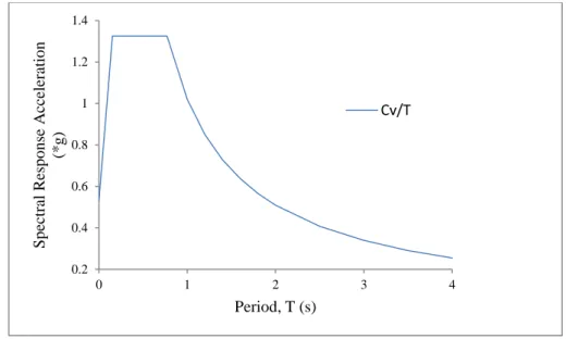
With the site characteristics as per NSCP 2010 the response spectrum was defined in Fig. 1. The seismic coefficients are Ca = 0.53 and Cv = 1.02 and using a 5% elastic damping.
Fig. 1 Response spectrum function definition
Load Combinations
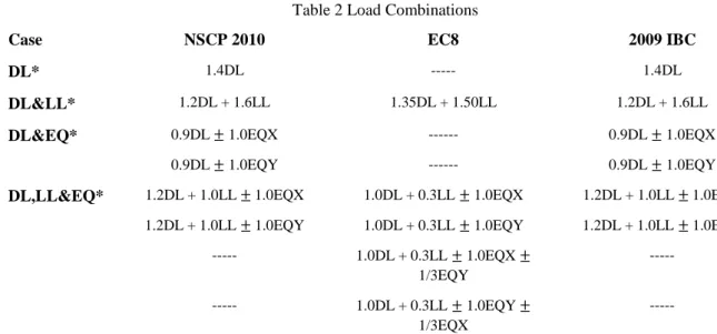
The different load combinations considered were used in the 3D model as shown in Table 2. From the load combinations given, EC8 (European Standard, 2004) considered the effects of earthquake forces in two directions.
0.2 0.4 0.6 0.8 1 1.2 1.4 0 1 2 3 4 Sp ec tr al R esp o n se A cc eler atio n (* g ) Period, T (s) Cv/T
Table 2 Load Combinations
Case NSCP 2010 EC8 2009 IBC
DL* 1.4DL --- 1.4DL
DL&LL* 1.2DL + 1.6LL 1.35DL + 1.50LL 1.2DL + 1.6LL
DL&EQ* 0.9DL 1.0EQX --- 0.9DL 1.0EQX
0.9DL 1.0EQY --- 0.9DL 1.0EQY
DL,LL&EQ* 1.2DL + 1.0LL 1.0EQX 1.0DL + 0.3LL 1.0EQX 1.2DL + 1.0LL 1.0EQX
1.2DL + 1.0LL 1.0EQY 1.0DL + 0.3LL 1.0EQY 1.2DL + 1.0LL 1.0EQY
--- 1.0DL + 0.3LL 1.0EQX 1/3EQY --- --- 1.0DL + 0.3LL 1.0EQY 1/3EQX ---
*DL (Dead-Load), LL (Live-Load) and EQ (EarthQuake load in X and Y directions respectively)
Sample RC buildings
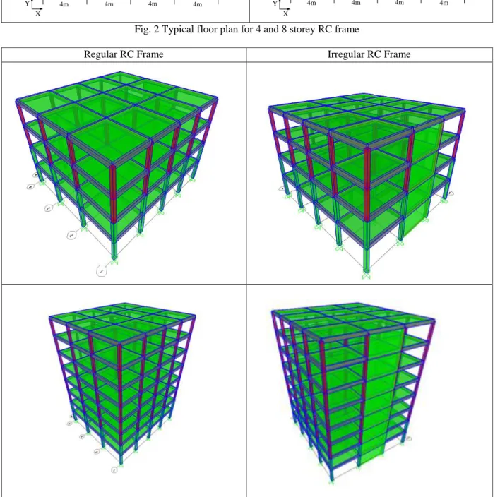
The codes define an “irregular structure” as one that has a certain geometric shape or in which stiffness and/or mass discontinuities exist. While a “regular structure” is one in which there is a minimum coupling between the lateral displacements and the torsional rotations for the mode shapes associated with the lower frequencies of the system. RC residential building of 15 m x 16 m has been considered for the analysis and comparison as shown in Fig. 2 (typical floor plan). There are four types of RC buildings utilized in this study. These buildings were: i) 4-storey regular frame, ii) 4-storey irregular frame (with shear wall), iii) 8-storey regular frame and iv) 8-storey irregular frame (with shear wall) as shown in Fig. 3.
RC framed descriptions
The RC building has a storey height of 3 m. Dead-load and live-load per floor are and , respectively. The material properties used are; for concrete and for reinforcement. The member sizes were: 300 mm x 400 mm column (ground floor to second floor), 300 mm x 300 mm column (third floor to last floor), 200 mm x 500 mm (typical beam section), 150 mm (slab thickness) and 200 mm (wall thickness). For the given framed, the following representative columns were analysed and compared C1, C3, C5, C6 and C8 (see Fig. 2). C1 and C5 are corner columns, C3 and C6 are side columns and C8 was middle (centre) column.
Analysis of the models
The sample buildings were analysed in terms of the following parameters: base shear, storey shear and the amount of reinforcement required in the representative columns at the ground storey. In order to determine the reinforcements needed by the representative columns the interaction diagrams provided by ACI Design Handbook was used as a reference (ACI SP-17(09), 2009).
Regular RC Frame Irregular RC Frame
Fig. 2 Typical floor plan for 4 and 8 storey RC frame
Regular RC Frame Irregular RC Frame
Fig. 3 3D Model of 4 and 8 storey RC frame
5 m 5m 5m 4m 4m 4m 4m Y X C1 C5 C6 C8 C3 5 m 5m 5m 4m 4m 4m 4m Y X C1 C5 C6 C8 C3 S H E A R W A L L
Base Shear
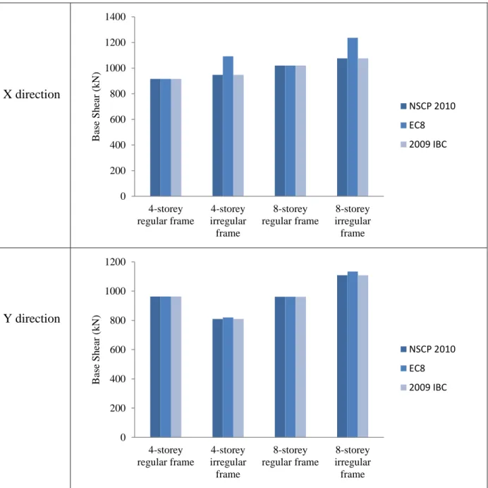
In this paper the response spectrum function presented in Fig. 1 with the given site characteristics were used in the computation of base shear for the NSCP 2010, EC8 and 2009 IBC. The maximum base shears obtained are presented in Fig. 4. Considering the base shear in the X direction, a 4% and 19% increase was observed between regular and irregular frame for NSCP 2010/2009 IBC and EC8 respectively. The same result was recorded for 8-storey frame. In the Y direction, a reduction of 19% and 18% was observed between 4-storey regular and 4-storey irregular frame for NSCP 2010/2009 IBC and EC8 respectively. Lastly a 16% and 18% increased of base shear was recorded between 8-storey regular and 8-storey irregular frame for NSCP 2010/2009 IBC and EC8 respectively.
X direction
Y direction
Fig. 4 Maximum base shear 0 200 400 600 800 1000 1200 1400 4-storey regular frame 4-storey irregular frame 8-storey regular frame 8-storey irregular frame B ase Sh ea r (k N) NSCP 2010 EC8 2009 IBC 0 200 400 600 800 1000 1200 4-storey regular frame 4-storey irregular frame 8-storey regular frame 8-storey irregular frame B ase Sh ea r (k N) NSCP 2010 EC8 2009 IBC
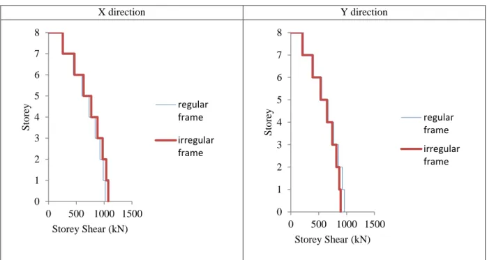
Storey Shear Profile
The maximum shear forces in the columns for 4-storey and 8-storey RC frames were shown in Fig. 5 and 6 for regular and irregular buildings. The introduction of irregularity for RC frame reduces the shear forces in X and Y directions. Average increase of the shear forces in the X direction was found to be 2-4% for 4-strorey RC frame. For irregular building, a 40% average decreased of shear forces in the Y direction. The same result was also observed for the 8-storey RC frame with a 3-5% increase in X direction. While for the irregular building, a reduction of about 6-7% was observed in Y direction.
X direction Y direction
Fig. 5 Storey Shear for 4 storey RC frame for NSCP 2010
X direction Y direction
Fig. 6 Storey Shear for 8 storey RC frame for NSCP 2010 0 1 2 3 4 0 500 1000 Sto rey Storey Shear (kN) regular frame irregular frame 0 1 2 3 4 0 500 1000 Sto rey Storey Shear (kN) regular frame irregular frame 0 1 2 3 4 5 6 7 8 0 500 1000 1500 Sto rey Storey Shear (kN) regular frame irregular frame 0 1 2 3 4 5 6 7 8 0 500 1000 1500 Sto rey Storey Shear (kN) regular frame irregular frame
Interaction Diagrams
The column axial load - bending moment interaction diagrams included herein (C1, C3, C5, C6 and C8) conform fully to the provisions of American Concrete Institute (ACI) code (ACI SP-17(09), 2009). The equations used to generate data for plotting the interaction diagrams were originally developed for ACI Special Publication SP-73. The original interaction
diagrams that were contained in 7 were subsequently published in Special Publication SP-17A5 (ACI SP-17(09), 2009).
The interaction diagrams were plotted in non-dimensional form. The vertical coordinate represents the non-dimensional form of the nominal axial load capacity of the section. The horizontal coordinate represents the non-dimensional nominal bending moment capacity of the section. The non-dimensional forms were used so that the interaction diagrams could be used equally well with any system of units (i.e. SI or inch-pound units) (ACI SP-17(09), 2009).
For the 4-storey RC frame, the representative columns C1, C3, C5, C6 and C8 are presented in Fig. 7 for the regular and irregular RC frames. As observed and compared with the interaction diagrams for the regular RC frame, the representative columns requires minimum steel ratio for all codes as per the NSCP 2010, EC8, and the 2009 IBC. The same result was also observed for the irregular frame wherein the increase in the steel ratio is not much notable. All representative columns require 1% reinforcement ratio as per NSCP 2010 (ASEP, 2010), EC8 (European Standard EC2, 2004) and 2009 IBC (ACI 318-08). It should be noted from the analysis of the codes, although they require the minimum value, EC8 provided a slightly higher values of axial load and moment capacity as compared with NSCP 2010 and 2009 IBC.
# 4 Storey Regular Frame 4 Storey Irregular Frame C1 C3 C5 C6 C8
For 8-storey RC regular frame, Fig. 8 shows the column axial load – bending moment interaction diagrams. The analysis was carried out individually for each column since the chosen columns requires more than the minimum steel ratio as required by NSCP 2010, EC8 and the 2009 IBC.
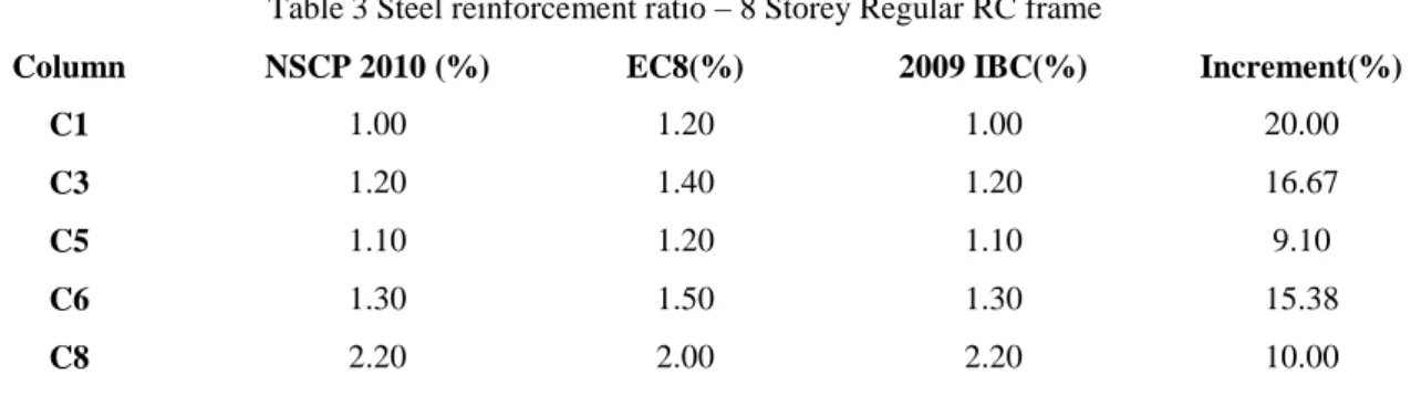
Table 3 Steel reinforcement ratio – 8 Storey Regular RC frame
Column NSCP 2010 (%) EC8(%) 2009 IBC(%) Increment(%)
C1 1.00 1.20 1.00 20.00
C3 1.20 1.40 1.20 16.67
C5 1.10 1.20 1.10 9.10
C6 1.30 1.50 1.30 15.38
C8 2.20 2.00 2.20 10.00
From Table 3, it was shown that C1, a corner column requires more reinforcement as per EC8 with a 20% increase when compared with NSCP 2010 and 2009 IBC. From the same table, C3, C5 and C6 followed next with the second highest increased in reinforcement ratio of 14% average. Finally, C8 has shown a 10% increased of reinforcements for NSCP 2010 and 2009 IBC as compared with EC8.
For 8-storey RC irregular frame, Fig. 8 shows the column axial load - bending moment interaction diagrams. The analysis was carried out again individually for each column, and the representative column requires a significant increase for reinforcement ratio.
Table 4 Steel reinforcement ratio – 8 Storey Irregular RC frame
Column NSCP 2010 (%) EC8(%) 2009 IBC(%) Increment(%)
C1 1.50 2.00 1.50 33.33
C3 1.30 1.60 1.30 23.00
C5 1.00 1.40 1.00 40.00
C6 1.20 1.60 1.20 33.33
C8 2.10 1.80 2.10 16.67
From Table 4, it was shown that C5 requires more reinforcement as per EC8 with a 40% increase when compared with NSCP 2010 and 2009 IBC. A 30% average increased in steel ratio for C1, C3 and C6 was observed for EC8 when compared with NSCP 2010 and 2009 IBC. Finally, C8 has shown a 16.67% increased of reinforcements for NSCP 2010 and 2009 IBC as compared with EC8.
It can be noted that the introduction of irregularity in the RC frames has resulted in the change of steel ratios for the representative columns. For the regular 8-storey RC frame, C1 requires more reinforcement, while for irregular RC frame it was C5. Furthermore, EC8 considered the effect of earthquake load in 2 directions and this was not considered in NSCP 2010 and 2009 IBC, and has resulted to an increase in the reinforcement ratio especially in the corner column. This effect is more pronounced in the irregular frame.
# 8 Storey Regular Frame 8 Storey Irregular Frame C1 C3 C5 C6 C8
CONCLUSIONS
A comparison of NSCP 2010, EC8 and 2009 IBC has been presented focusing on the building base shear, storey shear profile and column axial load - bending moment interaction diagrams in the standard occupancy of RC buildings. The structural model for the RC frames were created using SAP2000. The results for maximum base shear, story shear, axial loads and bending moments were compared and obtained using the NSCP 2010 response spectrum function. An overall increment in the reinforcement ratio was observed due to the irregularity in the frames. It was evident from the results that EC8 was found to be conservative as compared to NSCP 2010 and 2009 IBC. Majority of the representative columns requires an additional increase of 20% to 40% more reinforcements as compared with NSCP 2010 and 2009 IBC. It can also be noted that in the load combination cases, EC8 considered the effects of earthquake actions in both directions and this was not considered in the NSCP 2010 and 2009 IBC.
Therefore, the RC buildings designed using the EC8 can be considered conservative than the buildings designed using the NSCP 2010 and 2009 IBC. The results presented were applicable to residential buildings with standard occupancy and with typical loading conditions. The study presented in this paper increases the understanding of an important earthquake engineering issues concerning seismic design codes.
Furthermore, to generalize the results in this study an analysis on the substantial number of structures with different irregularities, characteristics and story levels should be made and finally the results of these analyses should be evaluated altogether.
ACKNOWLEDGMENTS
The authors gratefully acknowledge the funding provided by the Portuguese Foundation for Science and Technology (“FCT - Fundação para a Ciência e Tecnologia”), Portugal, through the research project with reference PTDC/ECM/102221/2008 and the Ph.D. grant of the second author with reference SFRH/BD/63032/2009.
REFERENCES
ACI SP-17(09). ACI Design Handbook. American Concrete Institute, Farmington Hills, Michigan, 2009, p. 1-26.
ACI 318-08. Building Code Requirements for Structural Concrete (318-08) and commentary (318R-08). American Concrete Institute, Farmington Hills, Michigan, 2008, pp. 465.
ASEP Inc., National Structural Code of the Philippines 2010 (C101-10) Buildings, Towers and Other Vertical Structures. ASEP Inc., Philippines, pp. 758.
Computer & Structures Inc. Structural Analysis Programs, SAP2000, Computer Software Package, Berkeley, California, USA, 2005.
European Standard. Eurocode 2: Design of concrete structures - Part 1-1: General rules and rules for buildings, Commission of the European Communities, European Committee for Standardization, 2004, pp. 226.
European Standard. Eurocode 8: Design of concrete structures for earthquake resistance - Part 1-1: General rules and rules for buildings, Commission of the European Communities, European Committee for Standardization, 2004, pp. 229.
International Code Council, Inc., 2009 International Building Code, Falls Church, VA, USA, 2009, p. 303-345.
Fardis, M. Seismic Design, Assessment and Retrofitting of Concrete Buildings based on EN- Eurocode 8, Springer Dordrecht Heidelberg London, New York, 2009.
Green, M. Building Codes for Existing and Historic Buildings, John Wiley and Sons Inc, USA, 2012, p. 19-37.
Melo J, Fernandes C, Varum H, Rodrigues H, Costa A, Arêde A. Numerical modelling of the cyclic behaviour of RC elements built with plain reinforcing bars, Engineering Structures, Taylor and Francis Group LLC, London, 2011, p. 273-286.
Rodrigues H, Varum H, Costa A. Simplified macro-model for infill masonry panels, Journal of Earthquake Engineering, Taylor and Francis Group LLC, London, 2010, p. 390-416.
Taranath, B. Reinforced Concrete Design of Tall Buildings, Taylor and Francis Group LLC, United States of America, Florida, 2010, p. 347-350.
Varum H. Seismic assessment, strengthening and repair of existing buildings, PhD Thesis, University of Aveiro (UA), Portugal 2003, pp. 508.