HOLOS, Year 32, Vol. 2 37
DEVELOPMENT OF AN EMBEDDED SYSTEM FOR REMOTE MEASUREMENT OF
DYNAMIC MAGNETIC FIELDS USING ZIGBEE
T. D. SILVA*, J. C. S. BORGES and A. A. A. F. SOARES Instituto Federal do Rio Grande do Norte – Campus Natal-Central
Article submitted in September/2014 and accepted in January/2016 DOI: 10.15628/holos.2016.2447
ABSTRACT
This paper aims to describe the development and implementation of an embedded system applied to remote measurement of dynamic artificial magnetic fields using Zigbee, which is a set of specifications for wireless data communication (based on IEEE standard 802.15.4). In the implementation of this system, Arduino
microcontrolled platforms were used integrated to a Hall effect sensor intended for measuring the strength of these dynamic magnetic fields. The Zigbee technology aims to enable the execution of real-time and in remote character of these measurements of magnetic field intensity, presenting them in a graphical view.
KEYWORDS: magnetic field measurement, Arduino, ZigBee.
DESENVOLVIMENTO DE UM SISTEMA EMBARCADO PARA MEDIÇÃO REMOTA DE
CAMPOS MAGNÉTICOS DINÂMICOS USANDO ZIGBEE
RESUMO
Neste artigo descrevemos o desenvolvimento e implementação de um sistema embarcado aplicado na medição remota de campos magnéticos dinâmicos artificiais utilizando o conjunto de especificações para comunicação de dados sem fio Zigbee (fundamentadas no padrão IEEE 802.15.4). Na implementação desse sistema foram utilizadas plataformas microcontroladas
do tipo Arduino integradas a um sensor de efeito Hall destinado à medição da intensidade desses campos magnéticos dinâmicos. A tecnologia Zigbee aqui usada visa possibilitar a realização em caráter remoto e em tempo real dessas medições de intensidade de campo magnético disponibiliza-as na forma de visualização gráfica.
HOLOS, Year 32, Vol. 2 38
1 INTRODUCTION
The technologies that involve the use of wireless data communication have the ability to ensure mobility between the data terminal elements of a communication channel while occurs the exchange of information between them.
Currently there are many devices using wireless technology for data transceiver. The best-known specifications for implementation of such technology are: Bluetooth, NFC (Near Field
Communications), Wi-Fi®, MMDS (Multipoint Microwave Distribution System), infrared, and LTE (Long Term Evolution). Among these specifications, include the ZigBee technology that performs a reliable wireless communication, at low transmission rates and low power consumption, which makes it suitable for applications of remote monitoring and remote control of processes.
Currently applied in several areas, the ZigBee was used in this work to transfer the measurements of the intensities of a dynamic artificial magnetic field carried out remotely via Hall effect sensor. An embedded system was implemented through an Arduino microcontrolled platform that operates together with that Hall sensor and a ZigBee transceiver module. The latter is responsible for the transfer of these remote measurements of intensity field to a base station [PC] - also equipped with an Arduino and ZigBee transceiver set-for the storage and display of these measurements.
The main motivation was to create an innovative product to be optimized and marketed in a future short-time, since there is not any similar device in market that performs such field measurements remotely.
2 THEORETICAL FOUNDATION
Hall effect sensors (HALLIDAY, RESNICK and WALKER, 2013) offer several practical advantages, such as: reduced physical size, optimal thermal stability and ability to detect and measure the intensity of dynamic magnetic fields.
Wireless personal area networks (WPAN), specified by the IEEE standard 802.15, have operating characteristics that highly coincide with the applications proposed in this article. One of the main characteristics of a WPAN become following those that guided the choice of this technology as an integral part of this research project: the low cost of implementation, little power consumption, the short range of the propagated signal and the small size of the devices used in the network installation (SANTOS, 2013).
Among available WPAN technologies, we adopted the ZigBee (MARÇAL, 2008), which corresponds to a set of specifications for wireless communication developed at the network layer of the RM-OSI model (KUROSE, 2014) and based on profound physical and link layers proposed by IEEE standard 802.15.4.
In a ZigBee network there are three distinct device types regarding their functionalities within the network. They are: the ZigBee coordinator (ZC), ZigBee router (ZR) and the ZigBee end device (ZED). The coordinator performs functions such as: network creation, transmission of warning, information management and storage of network nodes, besides routing messages between their interconnected nodes (KINNEY, 2003). The router is responsible for the forwarding
HOLOS, Year 32, Vol. 2 39
of packets between network devices, while the end device usually holds the host function dedicated to sensing actions (AZEVEDO, 2014).
In the case of the studied system, it was operated with the ZigBee 2.4 GHz band, with data rate up to 250 Kbit/s, in a peer-to-peer network whose communication infrastructure has only two devices: one acting as ZC and the other as ZED.
3 DEVELOPMENT OF MEASUREMENT SYSTEMS AND WIRELESS COMMUNICATION
The system developed in this research was implemented in two distinct stages. The first stage has been the integration of Hall effect sensor with the Arduino platform, thus starting the embedded system. The second integrated the ZigBee communication module to this system.3.1 INTEGRATION OF THE HALL EFFECT SENSOR WITH THE ARDUINO
In this stage, we integrated the Phidgets Magnetic Sensor (model 1108)-with Hall effect-based operation - to the Arduino platform (Duemilanove model). Such devices can be seen working together in Figure 1 (p. 4). The sensor is responsible for the magnetic field strength measurements by providing as transduction signal response an output voltage ranging from 0 to 5V, proportional to the intensity of the magnetic field measured.
The conversion formula to Gauss, standard unit in the international system of units for measurement of magnetic field strength, from the value of the voltage generated by the sensor is given according to the manufacturer PHIDGETS (2014) by:
Φ(G) = 500 – (Vin · 200) equation (1)
The sensor has three pins: a pin called power, always powered with +5V, a pin referred as ground pin, always powered with 0V, and the pin that works as analog output - response pin. The latter is connected to the Arduino analog port, which thereby performs reading of the voltage values supplied by the sensor.
HOLOS, Year 32, Vol. 2 40
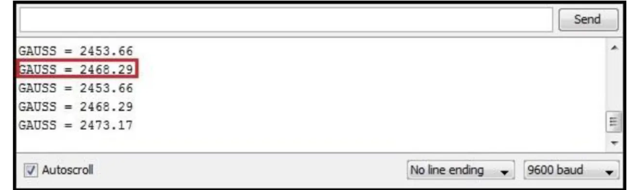
Through the icon Serial Monitor available in the IDE of the Arduino is possible to observe on a display the voltage values produced by the Hall effect sensor in real time.
In the case of this work, these values was displayed on the screen already converted to Gauss by the software stored in the Arduino that ran immediately the conversion formula (Equation 1) for voltage measures obtained by the sensor. An example can be seen in Figure 2.
The data collected by the Arduino may still be stored in EEPROM memory permanently available on the own platform – 512 Kbytes maximum size for the Duomilanove, without loss of collected information when turns off the Arduino from power supply (MONK, 2014).
Figure 2 – Screen provided by the Serial Monitor.
3.2 DATA COMMUNICATION VIA ZIGBEE
Wireless communication is a fundamental part of the proposed system in this paper because it enables the data exchange through the free space between the devices involved in the process even if these are tens of meters away from each other.
The proposal here examined was implemented with ZigBee wireless communication modules called XBees. These modules were chosen due to its simplicity of setting through a serial interface, in addition to the possibility of the establishment of networks and addressing modules to be operationalized via freeware software called X-CTU.
In this stage, it was added a second Arduino with a connected ZigBee reception module intended for remote capture of the data collected. At this point, the ZigBee network consisted of two XBees (XBEEPRO S1 model) modules for wireless communication, two XBees Shields (Electronics model) and two Arduinos (Duemilanove) to which the wireless modules were associated.
The XBees Shields used on both Duomilanove – a Shield in each - is a board that associates the Arduino to Xbee module as follows: the XBee module is connected to the XBee Shield, which in turn is connected to the board containing the Arduino. The complete set of the aforementioned components that comprise the ZigBee transceiver system.
3.2.1 The transmitter system
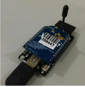
The transmitter system is formed by the sensor, an Arduino, a Shield XBee, and a Xbee module. To configure the XBee module, it is necessary the use of a device called XBee Explorer and the X-CTU. The XBee Explorer connects the Xbee module to the computer via USB 2.0 port. The XBee from the transmitter is configured as ZED and exchange information with the XBee module
HOLOS, Year 32, Vol. 2 41
from the receiving system, configured as ZC. In Figure 3 (p. 6), it is possible to see the XBee Explorer used.
The sensor measures continuously any magnetic fields exercised on it and sends these information to the Arduino - programmed to read these values on A0 analog port. This receives the data and sends to the XBee module. Communication between Arduino and XBee module occurs through the ports 2 and 3 of the Arduino, called TX and RX, respectively.
Figure 3 - XBee Explorer.
Finally, the XBee module, after receiving the values supplied by the Arduino, relays them using the wireless communication to the XBee module present in the receiving system. The transmission of information occurs in an interval of 100 ms. The transmitter system can be seen in Figure 4. From marked items, the XBee module is seen inserted on the XBee Shield - greater board. The Shield is inserted in the Arduino. The three markings in the middle of the figure are for the ports used in the Arduino: 5V, ground, 0V and the A0 analog port. The other component highlighted in Figure 4 is the Hall effect sensor.
HOLOS, Year 32, Vol. 2 42 3.2.2 The receiving system
The receiving system operates as follows: the XBee module remains constantly reading values, regarding the reading of sensor, which are sent by the XBee transmitter system. It receives the information and sends to the Arduino - using ports 2 and 3, as occurs in the transmitter.
The Arduino, in turn, sends this information to the computer via USB cable, however, using a serial connection. In this way, the information can be viewed through the Serial Monitor of the Arduino IDE or other software that can read these values through the serial port. The LabView ran in this work is an example of this type of software. The receiving system can be seen in Figure 5. The marking shows its connection with the computer, via USB, not only for power supply, but also for the transmission of information.
Figure 5 - Receiving system.
4 RESULTS
With all systems ready, tests were carried out. To verify the measurement performed by the sensor, a small magnet was used as a source of magnetic field to the sensor. Bringing it closer to the sensor, it might notice a gradual increase in the read magnetic field, notwithstanding the opposite occurred moving it away from the sensor. The following image (Figure 6, p. 7) show the sensor and the magnet used.
HOLOS, Year 32, Vol. 2 43
The interval between measurements were programmed in the Arduino to be held every 100ms and even with this interval considerably low, there was no packet loss or delays in communication.
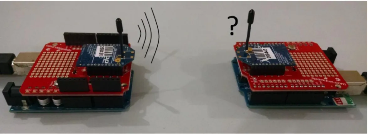
In terms of distance of effective communication of data, two tests were carried out: the first in an open environment and the following in a closed environment. In the first environment, the system managed to communicate, without loss or delays, 120 meters away. In the second environment, the distance achieved was more than 15 meters. The results were quite satisfactory in both tests, confirming the quality of ZigBee wireless communication performed by the used modules. Figure 7 shows both systems, transmitter and receiver.
Figure 7 – Transmitter (left) and receiver (right) systems.
For better visualization of the readings performed by the developed system, we plot the data captured in LabView (Figure 8). The part indicated by the letter "A" shows the reading at the time that the magnet was closer and, thereupon, away from the sensor, a situation perceived by the increase and decrease in the chart. In part "B", the same experiment was carried out, but with reversed polarity of the magnet. The part "C" is the same experiment of the "A". The part "D" shows the moment in which there is no approximation of the magnet on the sensor.
Figure 8 – Labview.
5 CONCLUSION
The tests conducted with the proposed system showed its good functionality and flexibility of application in diverse real situations, such as the direct measurement of the rotation speed of a
HOLOS, Year 32, Vol. 2 44
shaft or indirect measurement of the linear speed of a vehicle calculated from the rotation of one of their wheels.
In the measurements and tests performed, it was noticed that the Hall sensors are stable, sensitive to variation in field strength and enough accurate, operating flawless in the different tested frequencies.
As a future perspective, the implemented system enables the use of other types of sensors, such as temperature, humidity, electromagnetic field or gas, dedicated to a broad possibility of different applications.
6 REFERENCES
1. ANDERSON, Jeremy J. “Structural and Magnetic Properties of Neodymium - Iron - Boron
Clusters” (2010). Mechanical (and Materials) Engineering. Dissertations Master Science,
Lincoln, Nebraska, USA, 2010.
2. AZEVEDO, Tiago. Roteamento zigbee. Disponível em: <http://www.gta.ufrj.br/ensino/ CPE825/2006/resumos/TrabalhoZigBee.pdf>. Acesso em: 21 de junho de 2014.
3. BORGES, J.C.S.; LIMA FILHO, A.C.;BELO, F. A. Sensor Hall effecton analyses Mechanical Stress.
Journalof Mechanics Engineeringand Automation. v.5, p. (19-25), 2015. ISSN/ISBN:
2159-5275. doi: 10.17265/2159-5275/2015.01.003.
4. HALLIDAY, David; RESNICK, Robert; WALKER, Jean. Fundamentos de física: eletromagnetismo. Rio de Janeiro: LTC, ed. 9, v. 3, p(195-198), 2012.
5. KINNEY, Patrick. ZigBee technology: Wireless Control that Simply Works, 2003.
6. KUROSE, James F. e ROSSE, Keith W. Redes de computadores e internet: uma abordagem top-down. São Paulo: Pearson, p. (35-41), 2014.
7. MAIA, Thales Alexandre Carvalho. Projeto e Construção de um Gerador a Ímãs Permanentes
de Fluxo Axial para Turbina Eólica de Pequena Potência. Programa de Pós-Graduação em
Engenharia Elétrica da Universidade Federal de Minas Gerais. Belo Horizonte, 2011.
8. MARÇAL, Isabela Sachetim. Bluetooth e zigbee padrões para redes pessoais sem fio. Londrina, 2008. p(31-35).
9. MONK, Simon. 30 projetos com arduino. Tradução de Anatólio Laschuk. 2. ed. Porto Alegre: Bookman, 2014.
10. PHIDGETS. 1008 user guide. Disponível em: <http://www.phidgets.com/docs/1108_ User_Guide>. Acesso em: 5 de agosto de 2014.
11. SANTOS, Everton Luiz Ferret dos. A IEEE 802.15.4 como plataforma de comunicação de dados. Revista Ilha Digital, Florianópolis, v. 4, p(97-105), 2013.
12. ZIGBEE. ZigBee alliance. Disponível em: <http://www.ZigBee.org/>. Acesso em: 20 de junho 2014.