Joana Maria Gonçalves Freitas
outubro de 2015
Topography of Aligned PNIPAm Nanogels
Determines Cell Motility and Cytoskeleton
Architecture
Joana Maria Gonçalv
es F reitas Topograph y of Aligned PNIP Am Nanogels De termines Cell Mo
tility and Cytosk
ele
ton Architecture
UMinho|20
Joana Maria Gonçalves Freitas
outubro de 2015
Topography of Aligned PNIPAm Nanogels
Determines Cell Motility and Cytoskeleton
Architecture
Trabalho efetuado sob a orientação do
Professor Doutor Martin Zenke
RWTH Aachen
e do
Professor Doutor Miguel Gama
Universidade do Minho
Dissertação de Mestrado
Mestrado Integrado em Engenharia Biomédica
Ramo Engenharia Clínica
Nome: Joana Maria Gonçalves Freitas
Endereço eletrónico: [email protected] Número do cartão de cidadão: 14183014
Título da Dissertação: Topography of Aligned PNIPAm Nanogels Determines Cell Motility and Cytoskeleton Architecture
Orientador(es):
Professor Doutor Martin Zenke Professor Doutor Miguel Gama
Ano de conclusão: 2015
Designação do Mestrado: Mestrado Integrado em Engenharia Biomédica – Ramo Engenharia Clínica
É AUTORIZADA A REPRODUÇÃO INTEGRAL DESTA DISSERTAÇÃO APENAS PARA EFEITOS DE INVESTIGAÇÃO, MEDIANTE DECLARAÇÃO ESCRITA DO INTERESSADO, QUE A TAL SE COMPROMETE.
Universidade do Minho, ___ /___ /______ Assinatura: _______________________________________________________________
iii
Acknowledgments
There were several people who contributed to the realization of this work. Without the collaboration of all of them, the proposed goals could not be achieved and this work would not have been realized. Thus, I want to take this section to express my sincere gratitude to the people who have been involved in the successful completion of this work.
First, I would like to express my gratitude to Dr. Martin Zenke for the opportunity to work at his institute and for his expertise, constant support, enthusiasm and encouragement that contributed considerably to my dissertation work.
I am especially grateful to Dr. Antonio Sechi for mentoring me and for his teaching. His guidance helped me in all the time of research and writing of this dissertation. All the enthusiasm and all the advices that he gave me were very important in the development of all the phases of this project.
I am very grateful to Dr. Miguel Gama for being my supervisor in my university and for his attention and availability.
I am deeply grateful to Gülcan Aydin for supporting and teaching me during the whole work of this Master thesis.
I owe thanks to Patrick Wünnemann and other people from DWI (Leibniz Institute, Aachen) for preparing me the nanogels and for teaching and helping me with the AFM analysis and wrinkled PNIPAm substrates preparation.
My thanks also go to all Cell Biology lab members who helped and contributed to the nice atmosphere in the lab.
I also have to thank to Ana and Rita, my Erasmus roommates that spent an amazing time with me. They were my family during this period and provided me a fun environment and the necessary emotional support.
Last but not least, I thank to my family and to my friends, who were extremely important to me during this dissertation period. I am especially grateful to my parents, who supported me emotionally and financially, and to Luís, not only for the affection, comfort and constant encouragement but also for helping me in the revision of this work.
v
Topography of Aligned PNIPAm Nanogels Determines Cell
Motility and Cytoskeleton Architecture
Abstract
Tissue engineering has become a very important and rapidly changing field of biomedical research and it has important implications for medical practice. The effects of structured surfaces, such as grooves, on different cell types have been extensively investigated. When in contact with such substrates, cells become elongated, align with the grooves, and then migrate along grooves direction. This phenomenon is known as contact guidance. The ability of cells to adhere and move on specific substrates is important in the field of tissue engineering and biomaterials as it offers the possibility to modulate cell function.
The present study aimed to understand the influence of aligned PNIPAm nanogels topography on the adhesion, alignment and migration of cultured cells. Different cell types were seeded on structured nanogels to evaluate their movement and alignment, and some parameters of B16F1 cell’s motility, like speed and movement directionality, were analyzed. B16F1 cells were also used to evaluate the nanogel-cell interaction, using the fluorescent staining of different cell cytoskeleton structures such as vinculin, a protein present in focal adhesions. Moreover, protein-coated and uncoated nanogels were analyzed by atomic force microscopy to evaluate whether or not this coating would affect surface topography.
It was found that cells aligned and elongated in the direction of the nanogels. In addition, all analyzed cytoskeleton structures responded to the aligned nanogels. In the case of structured nanogels, focal adhesions were fewer, smaller and aligned along nanogel lines. Immunofluorescence experiments did not show big differences between cells seeded on glass coverslips and flat nanogels, suggesting that nanogel chemical composition did not affect cell cytoskeleton. Quantitative analysis of cell motility demonstrated that cell speed was lower in the presence of flat nanogels, compared to cells plated on glass coverslips. Furthermore, cells moved slower when they were along nanogel lines, maintaining a strictly defined directional movement.
Taken together, this project demonstrates that aligned PNIPAm nanogels could be used to influence cell’s cytoskeleton architecture and, therefore, cell behaviour, including adhesion and migration.
vii
Resumo
A engenharia de tecidos tem-se tornado numa área da investigação biomédica muito importante e de rápida evolução, tendo importantes implicações para a prática médica. Os efeitos de superfícies estruturadas em diferentes tipos de células têm sido extensivamente estudados. Quando em contacto com substratos ranhurados, as células tornam-se alongadas, alinhadas com as ranhuras, e migram na direção das ranhuras. O estudo desta influência de diferentes substratos no comportamento celular é importante na engenharia de tecidos e biomateriais, uma vez que oferece a possibilidade de modular a função das células.
O presente estudo tinha como objetivo compreender a influência da topografia de nanogeis alinhados de PNIPAm na adesão, alinhamento e migração de células em cultura. Para tal, foram cultivados diferentes tipos de células em nanogeis estruturados para avaliar o seu movimento e alinhamento, e foram também analisados alguns parâmetros da motilidade das células B16F1. As células B16F1 foram igualmente utilizadas para avaliar a interação célula-nanogel, utilizando a microscopia de fluorescência para visualizar diferentes estruturas do citoesqueleto celular, tais como a vinculina, uma proteína presente nas adesões focais. Além disso, os nanogeis revestidos e não revestidos com proteína foram analisados por microscopia de força atómica para avaliar se este revestimento iria ou não afetar a topografia da superfície.
Verificou-se que as células alinharam e alongaram-se na direção das linhas de nanogéis. Para além disso, todas as estruturas do citoesqueleto analisadas foram influenciadas por esta estrutura de nanogéis. No caso dos nanogéis alinhados, as adesões focais eram menores, estavam em menor número e alinhadas com as linhas de nanogéis. Os ensaios de imunofluorescência não mostraram grandes diferenças entre células cultivadas em lamelas de vidro e numa monocamada de nanogels, sugerindo que a composição química destes nanogéis não afeta o citoesqueleto celular. A análise quantitativa da motilidade das células demonstrou que a velocidade das mesmas foi inferior quando estas foram cultivadas na monocamada de nanogéis, em comparação com as células cultivadas em lamelas de vidro. Além disso, as células moveram-se com uma velocidade menor quando foram cultivadas nas linhas de nanogéis, mantendo um movimento direcional estritamente definido.
Em conclusão, este estudo demonstrou que os nanogéis PNIPAm alinhados poderiam ser utlizados para influenciar a estrutura do citoesqueleto celular e, por conseguinte, o comportamento das células, incluindo a adesão e migração.
ix
Table of Contents
Acknowledgments ... iii Abstract ... v Resumo ... vii Table of Contents ... ix List of Abbreviations... xiList of Figures ... xiii
Chapter 1 Introduction ... 1
1.1. Cell cytoskeleton ... 3
1.1.1. Actin filaments ... 3
1.1.2. Microtubules ... 5
1.1.3. Cell motility ... 6
1.2. Influence of substrate topography on cell behaviour ... 9
1.2.1. Nanotopography techniques ... 10
1.3. Preparation of structured surfaces ... 11
1.4. Cells used in the experiments ... 15
1.5. Objectives ... 16
Chapter 2 Materials and Methods ... 17
2.1. Cell culture ... 19
2.2. Preparation of nanogel modified surfaces ... 19
2.2.1. Preparation of wrinkles ... 19
2.2.2. Deposition of nanogels arrays on solid substrates ... 20
2.3. Atomic Force Microscopy analysis ... 20
2.4. Laminin and fibronectin coating ... 21
2.5. Video Microscopy ... 22
2.6. Immunofluorescence Microscopy ... 22
2.7. Analysis of cell motility ... 23
2.8. Statistical analysis ... 23
Chapter 3 Results ... 25
3.1. Aligned PNIPAm Nanogels ... 27
3.2. Nanogel-Cell interaction ... 29
x
3.2.2. Microtubules staining ... 31
3.2.3. EVL Staining ... 32
3.2.4. Vinculin staining ... 34
3.3. Cell movement on PNIPAm nanogel arrays... 36
3.3.1. NIH-3T3 cells align along nanogel lines ... 36
3.3.2. B16F1 mouse melanoma cells move in the direction of the grooves ... 37
3.3.3. Quantitative analysis of B16F1 motility ... 41
Chapter 4 Discussion ... 45
4.1. Aligned PNIPAm Nanogels ... 47
4.2. Nanogel-Cell interaction ... 48
4.3. Cell movement on PNIPAm nanogel arrays... 50
Chapter 5 Conclusions and Outlook ... 53
xi
List of Abbreviations
˚C - Degree Celsius % - Percent µm - micrometer µg - microgramADP - Adenosine diphosphate AFM – Atomic Force Microscopy Arp 2/3 - Actin-Related Protein2/3 ATP - Adenosine Triphosphate BSA – Bovine serum albumin C - Carbon
Cdc42 – Cell division control protein 42 cm - centimeter
cm2 – square centimeter
CO2 – carbon dioxide
DAPI – 4',6-diamidino-2-phenylindol
DMEM – Dulbecco's Modified Eagle Medium DNA - Deoxyribonucleic acid
ECM – Extracellular matrix
EGTA - Ethylene glycol tetraacetic acid
Ena/VASP - Enabled/vasodilator-stimulated phosphoprotein EVL – Ena/VASP like protein
FCS – Fetal calf serum GTP – guanosine triphosphate h – hour
IgG - Immunoglobulin G K - Potassium
KHz - Kilohertz
LCST – Lower critical solution temperature mbar- millibar
xii Mg - Magnesium MgCl2 - Magnesium chloride min - minute mL - milliliter mm - millimeter mM - Millimolar MT - microtubules NaCl – Sodium chloride nm - nanometer O - Oxygen PBS - Phosphate-buffered saline PDMS – Poly(dimethylsiloxane) Pen-Strep – Penicillin-Streptomycin PFA - Paraformaldehyde
pH - Negative decadic logarithm of H3O+ concentration
PIPES - Piperazine-N,N′-bis(2-ethanesulfonic acid) PNIPAm - Poly(N-isopropylacrylamide)
PVCL/AAEM – poly(N-vinylcaprolactam-co-acetoacetoxyethyl methacrylate) Rac - Ras-related C3 botulinum toxin substrate
RT – room temperature s - second
Tris - Tris(hydroxymethyl)aminomethane TBS - Tris Buffered Saline
xiii
List of Figures
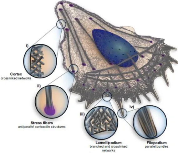
Figure 1 – Scheme of the cell with the different architectures indicated: i) cell cortex; ii) an example of a contractile fiber, the stress fiber; iii) the lamellipodia; iv) filopodia. The zoomed
regions highlight architectural specificities of different regions of the cell [14]. ... 4
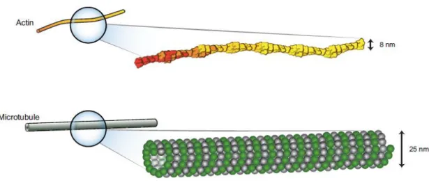
Figure 2 - Diameters and form of different cytoskeletal elements. Actin filaments are semi-flexible polymers with a diameter of 8 nm. Microtubules are rigid with a diameter of 25 nm [14]. ... 5
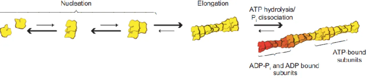
Figure 3 – The kinetics of actin assembly. Actin polymerization from the pool of actin monomers happens in two phases. The nucleation, is the formation of dimmers and trimers. This is followed by rapid elongation at the more dynamic end, the barbed end [14]. ... 6
Figure 4 - Distribution of adhesions and actin structures inside the cell, indicating the role of the different Rho family GTPases (Cdc42, Rho, Rac1) at specific regions in a migrating cell [74]. ... 7
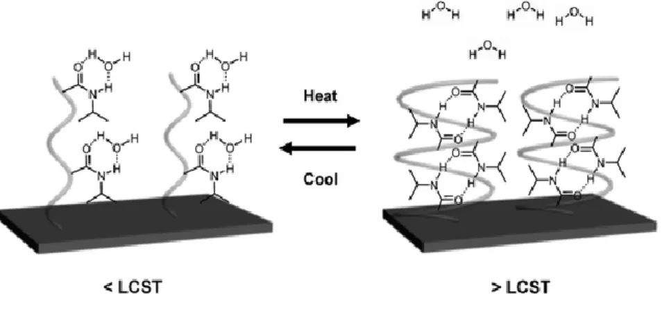
Figure 5 – Exemplification of the temperature-induced switching of a PNIPAm-modified surface. PNIPAm chains form intermolecular hydrogen bonds with water molecules at temperatures lower than the LCST (left) and form intramolecular hydrogen bonds between C=O and N–H groups at temperatures higher than the LCST (right). The PNIPAm surfaces show different cell adhesion below and above the LCST [39]. ... 13
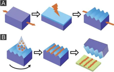
Figure 6 – The principles of wrinkling (A) and printing (B) are exposed. A: Stretched PDMS is treated with air plasma to create a hard top layer. Relaxation of the stress will induce wrinkles in this stiff top layer. B: Nanogels are spin-coated onto wrinkles to put the particles in the grooves of the substrate. Then it is showed the printing of the particles into planar surfaces [30]. ... 14
Figure 7 – Contrast phase image of high density NIH-3T3 cells. Scale bar: 100 µm [48]. ... 15
Figure 8 – Contrast phase image of high density B16F1 cells [75]. ... 15
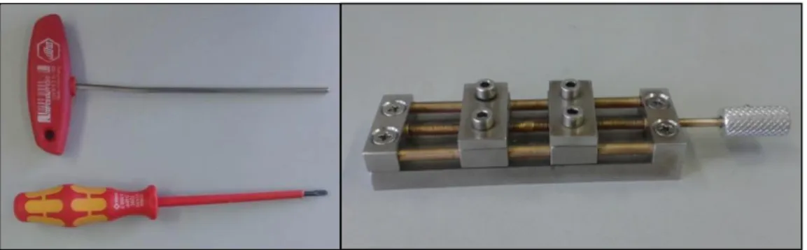
Figure 9 – Tools and apparatus used to stretch the PDMS stripes. ... 19
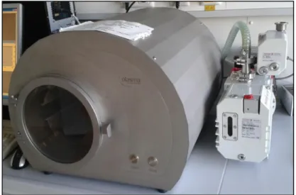
Figure 10 – Device used for air and argon plasma treatments. ... 20
xiv
Figure 12 – Schematic representation of the changes of directionality of cells moving on nanostructured wrinkles (A) or glass/unstructured nanogels (B). ... 23 Figure 13 – Aligned PNIPAm nanogel arrays by contrast phase microscopy. Transversal line represents a discontinuity (crack) in the ordered array structure. ... 27 Figure 14 – AFM analysis for PNIPAm nanogels without protein coating. Note that the nanogel lines are not perfect and almost every part of the image it is possible to see two or three nanogels deposited side by side or in zigzag form. ... 28 Figure 15 – AFM analysis from printed nanogels with fibronectin coating. There are some white spots in the image, due to existing precipitates. The fibronectin coating do not affect the wrinkled topography, as it is possible to see in this picture. Note the crack of nanogels in the lower part of the image. ... 28 Figure 16 – AFM analysis from printed nanogels with laminin coating. The wave length is not very regular, but it is possible to observe that this coating do not affect the topography of aligned PNIPAm nanogels. ... 29 Figure 17 – Organization of actin cytoskeleton in B16F1 cells plated on glass coverslips (left panels), flat nanogels (middle panels) or nanogel arrays (right panels). Note the flat morphology and the formation of lamellipodia and microspikes (arrows) in cells planed on glass or flat nanogels. Cells plated on nanogels arrays are elongated, do not have large lamellipodia and form long actin stress fibers. ... 30 Figure 18 – Organization of microtubules in B16F1 cells plated on glass coverslips (left panels), flat nanogels (middle panels) or nanogel arrays (right panels). Note the distribution of microtubules that originated from the cell center and grew toward cell periphery. Microtubules in cells plated on nanogels arrays are primarily orientated along the major cell axis. ... 31 Figure 19 – Distribution of EVL in B16F1 cells plated on glass coverslips (left panels), flat nanogels (middle panels) and nanogel arrays (right panels). EVL typically localizes at focal adhesion or microspikes tips (arrows) in cells plated on glass or flat nanogels. In cells plated on nanogels arrays EVL localizes to focal adhesions. ... 33
xv
Figure 20 – Distribution of vinculin in B16F1 cells plated on glass coverslips (left panels), flat nanogels (middle panels) or nanogel arrays (right panels). Note the formation of bigger and numerous focal adhesions in cells plated on glass. In cells plated on flat nanogels or nanogels arrays focal adhesions are fewer and smaller. Focal adhesions tended to align along the underlying arrays (arrows). ... 35 Figure 21 – Alignment of NIH-3T3 fibroblasts on PNIPAm nanogel arrays (left panel) or arrays coated with fibronectin (right panel). ... 36 Figure 22 – Morphology and orientation of B16F1 cells plated on glass coverslips (left panel), flat nanogels (middle panel) or nanogel arrays (right). Note the elongated shape and uniform orientation of cells on nanogel arrays. Cells on flat nanogels or glass acquired a flat morphology and random orientation. ... 37 Figure 23 – B16F1 cells move in a highly orientated manner on nanogel arrays. Arrows point to single cells that moved back and forth along arrays over a period of several hours. Note that dividing cells (put arrows) continued to respond to the topographic cue and re-acquired the same elongated shape and orientation they had before cell division. ... 38 Figure 24 – B16F1 cells move in a randomly manner on flat nanogels. Arrows point to some single cells that moved in different directions over a period of 4 hours. Note that the frequency of these snapshots is higher than in the case of nanogel arrays, because B16F1 cells move faster when the nanogels are not aligned. ... 39 Figure 25 – B16F1 cells move also in a randomly manner on glass coverslip. Arrows point to some single cells that moved in different directions over a period of 4 hours. ... 40 Figure 26 – Scheme obtained with ImageJ after motility analysis of B16F1 cells plated on glass coverslips, nanogels flat or nanogel arrays. Note that cells, when plated on nanogels flat or glass coverslips, move randomly and they have bigger moves. B16F1 cells plated on nanogel arrays moved along these arrays. ... 41 Figure 27 – Quantification of the average speed of B16F1 cells plated on nanogel arrays, flat nanogels or glass coverslips. In the box plots the line in the middle of the box indicates the
xvi
median: the top line indicates the 75th quartile, whereas the bottom line indicates the 25th
quartile. Whiskers represent the 10th (lower) and 90th (upper) percentile, respectively. ... 42
Figure 28 – Quantification of the directionality of B16F1 cells moving on nanogel arrays, flat nanogels or glass coverslips. In the box plots the line in the middle of the box indicates the median: the top line indicates the 75th quartile, whereas the bottom line indicates the 25th
1
3
1.1. Cell cytoskeleton
The cytoskeleton is a network of filamentous proteins, frequently defined as the part of a cell that does not dissolve when the membrane is destroyed by detergents. The skeleton’s filaments are composed of three types of protein biopolymers – actin filaments, intermediate filaments and microtubules – and the many accessory proteins that bind to them [1], [2]. These three elements do not have only a structural function: together with accessory proteins, they regulate many cellular functions, such as motility [3]. Thus, the cytoskeleton generates cell’s mechanical forces and also transmits mechanical forces from the cell membrane to the nucleus, so the deformable cytoskeleton structure gives a physical basis for the transduction of mechanical signals into biochemical signals [4].
1.1.1. Actin filaments
Actin filaments are linear polymers of the globular protein actin. The globular monomer (G-actin) polymerizes into filamentous actin (F-actin) that appears in electron micrographs as two right-handed helices wound around each. Actin filaments have a diameter of 8 nm and can reach lengths of 30 to 100 µm in vitro, and at least several microns in vivo. Although they appear very stiff in light and electron micrographs, actin filaments are remarkably flexible on a µm length scale. Almost all mechanically relevant properties of actin filaments – stiffness, length, lateral or orthogonal aggregation – can be regulated by many actin-binding proteins [1].
Actin is arranged in parallel bundles forming the filopodia and in a dense meshwork forming lamellipodia, at the leading edge of the cell. Filopodia are transitory and thin hairlike protrusions, containing parallel actin bundles. Lamellipodia often also include parallel bundles of actin filaments called microspikes that may develop in filopodia when they protrude beyond the front edge. Some filopodia are disposed perpendicularly to the front of the lamellipodium. These filopodia are immobile relative to lamellipodium position but not substrate and their elongation is only driven by actin polymerization at their tips. Some filopodia are oblique relative to the leading edge, and move laterally with respect to the substrate and the lamellipodium[2], [5].
Actin filament network is involved in the reorganization of cell-shape, establishing and maintaining the form and orientation of nuclei [6], and cell motility (polymerization and depolymerization of actin filaments) [7], [8]. These processes can also be regulated by the actin binding proteins, such as Arp 2/3 complex, that regulates the branching of actin networks and is important for forward protrusion [9]. Ena/VASP are other proteins that regulate actin assembly
4
and cell motility. They are localized in areas of dynamic actin restructuring like the leading edge of lamellipodia and at the tips of filopodia and other actin-dependent intracellular structures, such as focal adhesions or periodic spots along stress fibers [8], [9].
Figure 1 – Scheme of the cell with the different architectures indicated: i) cell cortex; ii) an example of a
contractile fiber, the stress fiber; iii) the lamellipodia; iv) filopodia. The zoomed regions highlight architectural specificities of different regions of the cell [14].
5
1.1.2. Microtubules
The microtubules (MTs) are formed from the complex polymerization of αβ heterodimers of tubulin, which have a positive end, close to the cell membrane, and a negative end, close to the cell center. MTs have the form of hollow cylinders of small diameter (approximately 25 nm) whose polymerization and depolymerization from a pool of tubulin monomers depend on the hydrolysis of GTP (guanosine triphosphate) [3]. The walls of the microtubule are composed of 5 nm diameter linear protofilaments disposed in parallel. Because of their larger diameter and tubular structure related to actin filaments, microtubules are much more rigid [1].
The microtubules are found in all cell types (except erythrocytes) among vertebrate animals. They are particularly numerous in the brain neurons, where they represent about 20% of soluble proteins [3].
Microtubules are intricately and dynamically linked to actin and some of their functions include the movement of cells and the maintenance of cell polarity. Cell polarity is both structural and functional. It implies that certain activities of the cell are located in one of the cell poles [3]. Microtubules have also mechanical influence on the nuclear envelop and chromosome dynamics. Like in the case of actin filaments, microtubule stability, structure and polymerization are affected by microtubule associated proteins [1], [6].
Figure 2 - Diameters and form of different cytoskeletal elements. Actin filaments are semi-flexible
6
1.1.3. Cell motility
Movement is one of the most important characteristics of living organisms, and cells from an extensive variety of tissues are able to move. When explanted from the surrounding tissue and placed in culture, such cells have been shown to adhere to the substrate and then to migrate randomly over the surface [10].
Cell motility is one of the functions regulated by cell cytoskeleton. Cell motility plays an important role in numerous physiological and pathological processes. It is involved, for example, in processes such as morphogenesis, wound healing, response to infections by the immune system and progression of various diseases including cancer metastasis [11], [12].
Cell migration mechanism involves, in general, the protrusion of pseudopodia to make an initial contact with the ECM, the formation of new adhesions, followed by cell contractions, and the release of rear adhesions [12], [13]. In order to have a protrusion of the lamellipodium, the actin needs to polymerize. This polymerization depends on presence and concentration of Mg2+,
K+, ATP and actin-G and it begins after a latency period, the nucleation phase. During the
nucleation, two or three actin molecules join to form dimmers and trimers that act as nucleating sites. Then, in the polymerization, the G-actin molecules associate with each other quickly (Figure 3). The monomers bind to the filament at the same speed at which they separate. Several actin-binding proteins determine the nucleation and polymerization and, in consequence, the position and length of the microfilaments. During nucleation and polymerization an ATP molecule fixes on the binding site of each actin-G molecule. Hydrolysis of ATP into ADP causes polymerization. ADP remains fixed on the monomers located in F-actin. This polymerization in lamellipodium is responsible for the localized and exploratory extensions of the cell [3].
Figure 3 – The kinetics of actin assembly. Actin polymerization from the pool of actin monomers
happens in two phases. The nucleation, is the formation of dimmers and trimers. This is followed by rapid elongation at the more dynamic end, the barbed end [14].
This dynamic is controlled by several proteins such as small GTPases. The Rho GTPases family is very important for the regulation of both dynamic properties of the actin and the
7
microtubule cytoskeleton. One of the members of this family, Rac, controls the regulation of a signal transduction pathway that leads to the formation of lamellipodia, and another member, Cdc42, is responsible for the formation of filopodia. Adhesion of the cell is also part of its movement and the cell surface glycoproteins that are responsible for this are connected to the microfilaments through transmembrane proteins – integrins. These proteins transmit signals across the cell membrane, and coordinate the organization of the cytoskeleton in conjunction with the Rho family [9], [10].
Related to the role of actin filaments and microtubules in cell migration, in some cells, the protrusion is only driven by actin polymerization and in other cells, actin filaments organized in stress fibers limit membrane extension, which in this case is promoted by microtubules and their relaxing effect on stress fibers. However, in general, both actin and microtubules contribute to protrusion formation [2].
The sites where integrin and proteoglycan mediated adhesion links to the actin
cytoskeleton are the focal adhesions, where the cell membrane lies within 30 nm of the substrate [15]. The components of focal adhesions are diverse and include scaffolding molecules, GTPases, and enzymes such as kinases, phosphatases, proteases, lipases and several hundred
Figure 4 - Distribution of adhesions and actin structures inside the cell, indicating the role of the different
8
different proteins that together, critically influence a large number of integrin mediated cell signaling events such as cell survival and proliferation, contraction, migration and differentiation [16], [17]. Thus, integrins are an important group of adhesive transmembrane receptors that are intimately connected with the focal adhesions and that mechanically link the extracellular matrix with the cytoskeleton [18].
One of the major proteins forming focal adhesions is vinculin. Vinculin is a F-actin binding protein that provides a mechanical link, influences contractility and controls cell signaling processes [19]. Vinculin binds both talin and α-actinin and is very important for cell function and it is verified by the finding that cells genetically modified without vinculin are able to form temporary protrusions, but unable to form stable contact with the surface or directed locomotion [1]. Furthermore, deregulation of vinculin results in altered cell adhesion, contractility, motility and growth [19].
There are four different structures of focal adhesions: focal complexes that are small focal adhesions in the periphery of migrating cells; focal adhesions that are either in the periphery or centrally on 2D rigid surfaces; fibrillar adhesions that form as an elongation of focal adhesions; and 3D matrix adhesions [9], [20].
The cell migration process is quite complex and frequently influenced by an ample variety of stimuli, both external and internal. As an internal stimulus, cell migration can be influenced by the general state of the cell, such as the present mitotic phase of the cell health, the degree of differentiation in the case of stem cells, among others. As examples of external factors there are the mechanical forces that act on the cell, environmental conditions like pH and temperature, the presence of chemical factors, and the cell-cell contact determined by the cell density [12].
The visualization and monitoring of various aspects of cell behaviour, like cell shape, direction of cell migration and cell orientation, are extremely important for researchers to be able to understand the mechanisms that are behind cell migration. The mechanisms and cell differential responses to various types and dimensions of substrate topography are still quite unknown [21]. Phase contrast microscopy is the most widely used contrasting technique for viewing live cells. This happens because of the relatively simple configuration of microscopy instruments, low costs involved, the capacity to monitor the cells without staining and also the phototoxicity of short wavelength light used in fluorescent microscopy [22].
9
1.2. Influence of substrate topography on cell
behaviour
The extracellular matrix (ECM) provides a mechanical support for cells, but it also has influence in fundamental functions of the cells it is in contact with, such as migration, differentiation, proliferation and apoptosis [23]. Chemical and physical interactions between receptors on cell membranes and the ECM mediate cell behaviour [24].
The interactions of different cell types with some topographical textures, particularly microgrooves and ridges, have been investigated by many authors. These studies form the basis for the development of materials for cell culture substrates artificial organs and disposable medical devices.The phenomenon that is characterized by the response of cells to micron or sub-micron scale structures is known as contact guidance. Substrates with grooves cause various cell responses, such as cell alignment and migration along the grooves and ridges [25], [26].
Kaiser et al. analyzed the effect of topography on cell shape, cell orientation, migration angle, and velocity with different structured parallel line patterns and concluded that the response of the surface structure might be much more complex than generally assumed, showing that, the degree of alignment depends on the groove depth and width and varies between different cells [21].
The effect of nanotopography on cell migration is usually observed in cells cultured on nanogratings. Many cell types have exhibited an influence on migration direction, happening in the direction of the grating axis. Enhanced migration is a response typically attached with elongated morphology and alignment of cell body with the nanograting axis. Possibly the most obvious effect of nanotopography on cell function is the influence in cell geometry. Many cell types typically respond to nanogratings by simultaneously aligning and elongating in the direction of the grating major axis, which has been observed in various cases [25].
These studies are very important to understand the influence of some stimulus on cell behaviour, which can be engineered to control many aspects of cell function. Engineering substrates to induce required cell phenotype and genotype may become an important element in the design of a scaffold for tissue engineering applications. Substrate nanotopography can also be utilized as a tool for the study of complex cellular functions such as adhesion, cytoskeleton reorganization, migration, and cell polarization. In this case, nanotopographic arrangements can be incorporated in large areas with relative ease, allowing large-scale cell culture. For example,
10
nanograting substrates can be used to study the contact guidance and migration in vitro. Engineers could then use these new findings as the basis for the design and manufacture of the next-generation synthetic nanotopographic substrates [25].
1.2.1. Nanotopography techniques
The perfect nanofabrication method for regular study of size-dependent properties would be inexpensive and flexible in nanoparticle size, shape and spacing parameters. Numerous standard lithographic techniques are normally used to create nanostructures with controlled shape, size, and interparticle spacing. By far, the most extensively used is photolithography. Photolithography is a method that uses photons to print micro and nano patterns that can’t be achieved by human hands. It has a planographic process where printing and non-printing areas are in the same level [27].
Developments in micro- and nanofabrication technologies have allowed for the production of patterns and the analysis of cell behaviour on patterned surfaces [23]. However, techniques such as photolithography are expensive, time consuming, require access to intricate equipment and only work with inorganic substrates, which limits their application in cell behaviour. Therefore, alternative approaches have been studied [25], [28].
11
1.3. Preparation of structured surfaces
A simple method for the preparation of structured surfaces is the process of wrinkling. The concept of wrinkling was studied by Cerda and Mahadevan, who developed a quantitative wrinkling assay for the mechanical characterization of thin solid membranes [29]. In the last decade, different methods were developed for the production of wrinkles, like evaporation of metal films onto elastomers, buckling of thin polymeric sheets or plasma treatments [30].
During the last few years, silicone rubbers have gradually gained market share from porcelain and glass as exterior isolation and protective materials. High hydrophobicity, contamination resistance, and long-term endurance made the poly(dimethyl siloxane) (PDMS) a very useful polymer for these applications. So, PDMS is a low-density silicone rubber with highly hydrophobic surface properties, low surface energy, and high fracture toughness over a large range of temperature [31], [32].
PDMS has also been widely used as a stamp for printing different patterns in various substrates. Numerous approaches where PDMS is used as a stamp to move molecules of one ink to a specified substrate by contact have been reported. Because of the elastomeric nature of PDMS, this ink can be transferred to a non-planar substrate with a flat or non-flat stamp [32].
Oxygen plasma has been widely used to modify the surfaces of PDMS. These studies showed that oxygen plasma treatment caused permanent chemical changes in the near-surface region of PDMS. Studies using X-ray photoelectron spectroscopy on plasma-treated samples demonstrated a rapid substitution of carbon atoms by oxygen atoms, which led to the formation of hydrophilic surfaces [31], [33]. Bowden et al. [34]described a technique for generating waves on PDMS using the oxygen plasma treatment that forms a thin, stiff silicate layer on the surface of the PDMS rubber. The creation of such a silica-like layer caused changes in the PDMS mechanical properties.
Materials that are gaining biomedical importance are microgels. Over the past few years, microgels have attracted a considerable scientific attention by biologists, chemists and physicists. Microgels are intramolecularly crosslinked macromolecules with colloidal size and can be constructed from a huge diversity of different monomers. Microgels swell in a good solvent, leading to a sponge-like swelling behaviour [30], [35]. Microgels habitually have structural and property characteristics that make them attractive for various types of biomedical applications, like drug delivery. They are likely to have good biocompatibility if they have mostly water in the
12
swollen condition. It is simple to prepare negative or neutral particles, which is also advantageous for biocompatibility [35].
Depending on the microgel composition, it is possible to control microgel swelling by stimuli such as temperature, pH, ionic strength, electric or magnetic field, light and/or chemical and biological stimuli and consequently microgels have a wide range of applications that include sensors, drug delivery, gene delivery and tissue engineering [30], [36], [37].
Considerable research has been made on one temperature-sensitive polymer, poly(Nisopropylacrylamide) (PNIPAm), and its copolymers for biomedical applications. Poly(NIPAm) has a low critical solution temperature (LCST) at 32 ˚C in aqueous solutions. LCST is the temperatures at which this polymer experiences a phase change from a soluble state to an insoluble state. Thus, under its LCST, PNIPAm polymer has an extended conformation, but when warmed over the LCST, the polymer suffers a phase transition to form a collapsed morphology, expelling the solvent. It has been suggested that this induced phase transition of PNIPAm in aqueous solution is principally due to the thermal destruction of hydrogen bonds between water molecules surrounding hydrophobic structures in NIPAm, and a greater interaction between the hydrophobic segments on the polymer, increasing temperature [38]–[40].
There has been a large amount of work reported for drug delivery using PNIPAm nanogels. The potential for these nanogels to be used as an injectable delivery system for drugs was first shown by Snowden [41], [42]. However, one disadvantage of PNIPAm in drug delivery is that this nanogel is not resorbable, limiting its use in temporary implantation applications, since that having a non-degradable polymer in the human body possibly will origin a chronic inflammatory response [38], [43].
Another application of PNIPAm nanogels is the controlled cell attachment and detachment without enzymatic or mechanical treatments that has been widely studied by many researchers [37], [44]. This is linked with the possibility of exposing or concealing surface features and the change in hydrophilicity, which accompanies the change in the degree of swelling [37].This cell sheet manipulation techniques can be applied to many types of cell and tissue structures, including tubes, solid masses, or bags. It is possible that two or three-dimensional cell sheet manipulation – cell sheet engineering – can be a useful technique in the future of tissue engineering and regenerative medicine [45].
13
Figure 5 – Exemplification of the temperature-induced switching of a PNIPAm-modified surface. PNIPAm
chains form intermolecular hydrogen bonds with water molecules at temperatures lower than the LCST (left) and form intramolecular hydrogen bonds between C=O and N–H groups at temperatures higher than the LCST (right). The PNIPAm surfaces show different cell adhesion below and above the LCST [39].
An attractive technique is to merge the flexible microgel chemistry with topographically enforced cell growth. Colloidal particles can be aligned in the grooves of wrinkles PDMS substrates, like was done by Lu et al. [46] who reach an structured deposition by dip coating.
PDMS substrate can also be used as a stamp for printing or molding microgel particles on surfaces, to prepare regular groove patterns in the nano scale. Horn et al. [47] used this process to prepare linear patterns of the tobacco mosaic virus on surfaces and Hiltl et al. [30] produced lines from poly(N-vinylcaprolactam-co-acetoacetoxyethyl methacrylate) (PVCL/AAEM) and poly(N-isopropylacrylamide-co-N-vinylcaprolactam) (PNIPAm/VCL) particles. In this case, after the process of wrinkling of PDMS, nanogels were pre-aligned in these grooves by spincoating and transferred by pressing the PDMS stamp onto the substrate (Figure 6).
14
Figure 6 – The principles of wrinkling (A) and printing (B) are exposed. A: Stretched PDMS is treated with
air plasma to create a hard top layer. Relaxation of the stress will induce wrinkles in this stiff top layer. B: Nanogels are spin-coated onto wrinkles to put the particles in the grooves of the substrate. Then it is showed the printing of the particles into planar surfaces [30].
15
1.4. Cells used in the experiments
In this work, two cell types were used to study the influence of the topography of aligned PNIPAm nanogels in the motility and cytoskeleton architecture of cultured cells.
NIH-3T3 cells are mouse fibroblasts that have been widely used to evaluate the topography influence on cell behaviour. This cell line is a suitable transfection host and is highly sensitive to sarcoma virus focus formation and leukemia virus propagation and has proven to be very useful in DNA transfection studies [48].
B16F1 cells are mouse melanoma cells and they are characterized by high migratory potential and invasive growth [49], what makes them appropriate cells to evaluate cell motility. This cell type is highly metastatic. Migrating melanoma cells exhibit characteristic sheet-like membrane extensions called lamellipodia at their leading edge, which are induced by growth factor stimulation [50]. The morphology of B16F1 cells is a mixture of spindle-shaped and epithelial-like cells. This cell line is also a suitable transfection host [48].
Figure 7 – Contrast phase image of high density NIH-3T3 cells. Scale bar: 100 µm [48].
16
1.5. Objectives
Tissue engineering has become an important and quickly evolving area of biomedical research with important implications for medical practice. As migration and other cell responses, such as adhesion and proliferation, are dependent on cell–materials interactions, numerous reports have examined the influence of the surface topography on these responses [51]. In the case of nerve regeneration, the observation of a better migration on a specific topography can also have implications in the design of guidance channels. For example, tubular conduits with nanogratings could improve the migration of Schwann cells into the damaged place to promote axonal regeneration [25]. The interactions between cell membranes and the three-dimensional extracellular matrix are well characterized, but when considering the biomaterial or tissue engineering field, it still has to be studied. This way, in order to understand these mechanisms behind cell–surface interactions, it is crucial to make reports about how surface characteristics influence cell behaviour [21], [24].
The goal of this work was the evaluation of the influence of the topography of aligned PNIPAm nanogels on the adhesion, alignment and migration of cultured cells. Moreover, the contribution of protein coating was analyzed.
Henceforth, the specific aims of this work are:
- Evaluation of the nanogel-cell interaction, using the fluorescent staining of different cell cytoskeleton structures
- Analysis of the alignment of different cell types to the nanogel structure
- Study of motility of B16F1 mouse melanoma cells on aligned PNIPAm nanogels, including parameters such as speed and orientation.
17
19
2.1. Cell culture
NIH 3T3 cells and B16F1 cells were grown in high glucose Dulbecco’s modified Eagle medium (DMEM) containing 10% FCS, 1% Penicillin/Streptomycin (Pen/Strep) and 1% L-Glutamine. Cells were seeded on different supports at a density of 50.000 cells per plate (in 3 mL).
2.2. Preparation of nanogel modified surfaces
2.2.1. Preparation of wrinkles
PDMS was prepared using a Sylgard 184 elastomer kit by mixing Sylgard 184 monomer and Sylgard 184 base at a weight ratio of 10:1. The mixture was poured into a petri dish and leveled with rubbers to obtain thick films of 3 mm and then let it at ambient conditions to allow the solvents to evaporate overnight. Afterwards, PDMS was cured at 80 ˚C for 2 h in an oven. Cross-linked PDMS was cut into ≈ 2.0 cm x 1.0 cm stripes. The stripes were then clamped onto a custom-made stretching apparatus (Figure 9), expanded to 130% of their original size and exposed to air plasma treatment (Figure 10) for 480 and 900 s at 0.2 mbar, to obtain 1000 nm and 1500 nm wrinkles, respectively. The stripes were then slowly relaxed thus leading to the formation of nanostructured surfaces, which were clearly visible as iridescent areas.
20
2.2.2. Deposition of nanogels arrays on solid substrates
Glass coverslips were successively cleaned in an ultrasonic bath with acetone, deionized water and isopropanol for 5 min each, followed by air-drying. This solid substrate was activated with air plasma treatment for 300 seconds at 0.2 mbar. Then, the wrinkled PDMS and the solid substrate were activated with air plasma for 10 seconds at 0.2 mbar and immediately used. For the molding process, 20 μL of nanogel solution were deposited onto the substrate and the PDMS template was pressed on top. The substrates, thus obtained, were dried overnight before removing the PDMS stamp. After removing the stamp, the presence of iridescent areas indicated the successful preparation the nanostructured surfaces. Afterwards, the nanostructured surfaces were exposed to argon plasma treatment for 10 seconds to promote the fixation of the nanogels to glass surface.
2.3. Atomic Force Microscopy analysis
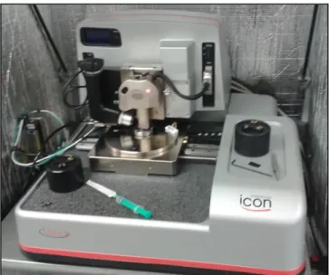
Atomic force microscopy analysis was performed to determine whether fibronectin and or laminin coating altered the topography of nanostructured surfaces. Uncoated nanostructured surfaces served as controls. Nanogel-patterned substrates in dry state were analyzed by atomic force microscopy (Veeco Dimension ICON with OTESPA tips (278-357 kHz, 12-103 Nm-1) - Figure
11) in tapping mode. For the liquid-cell measurments (MSCT-E tips (26-50 kHz, 0.10 Nm-1)) the
analysis was done in PeakForceQNM® mode.
21
2.4. Laminin and fibronectin coating
Glass coverslips were coated with 25 μg/mL of laminin (L2020, Sigma, Germany) in laminin buffer (150 mM NaCl, 50 mM Tris pH 7.5). A volume of 400 μl was used to coat an area of about 1 cm2. Coating was done at 37 ˚C for 2 hours followed by washing with laminin buffer to
remove unbound laminin. Coated coverslips were stored in laminin buffer until cells were ready to be seeded. For fibronectin coating, glass coverslips were coated with 50 μg/mL of Fibronectin (L7117, Merck Millipore, Germany) in PBS (150 mM NaCl, 50 mM Tris pH 7.5). A volume of 400 μL was used to coat an area of about 1 cm2. Coating was done at 4 ˚C for 24 hours followed by
washing with PBS to remove unbound fibronectin. Coated coverslips were stored in PBS until cells were ready to be seeded.
22
2.5. Video Microscopy
For live cell imaging, cells were seeded on glass, unstructured nanogels or nanostructured surfaces at a density of 50.000 cells (in 3 mL). After 24 hours, cells were monitored during 16 hours by time-lapse video microscopy an Axiovert 200 microscope (Carl Zeiss) equipped with a Plan-Apochromat 10x objective and a cooled, back-illuminated charge-coupled device camera (Cascade 512B; Princeton Instruments, Trenton, NJ) driven by IPLab Spectrum software (Scanalytics, Fairfax, USA). During image acquisition, cells were maintained at 37 ˚C and 5% CO2 using a heating stage and CO2 controller (Pecon, Germany).
2.6. Immunofluorescence Microscopy
For immunofluorescence microscopy, 24 h after seeding, cells were fixed with 4% paraformaldehyde in cytoskeleton buffer (10 mM PIPES, 150 mM NaCl, 5 mM EGTA, 5 mM glucose, 5 mM MgCl2, pH 7.0) for 30 min at room temperature (RT) and then extracted with 0.1% Triton X-100 in cytoskeleton buffer for 1 min at room temperature. The actin cytoskeleton was labelled with Alexa 594-conjugated phalloidin (1:300 in 1% BSA/TBS) (Molecular Probes, Eugene, USA). Nuclei were labeled with the DAPI (1:1000 in 1% BSA/TBS). For vinculin labeling, cells were fixed with 1% PFA/0,5% Tx-100 (in PBS pH 7.0) for 15 min at room temperature and then, after washing with PBS three times, incubated with 4% PFA pH 7.0 for 10 minutes. Vinculin was labeled using an anti-vinculin antibody (Sigma; 1:100 in 1% BSA/TBS) followed by Alexa 594-conjugated goat anti-mouse IgG (1:500 in 1% BSA/TBS). For microtubules labeling, anti-tubulin YL1/2 antibody was used followed by Alexa 594-conjugated goat anti-rat IgG (1:500 in 1% BSA/TBS). Evl was labeled using the monoclonal antibody 84H1 [52] (1:100 in 1% BSA/TBS) followed by Alexa 488-conjugated goat-anti mouse IgG (1:300 in 1% BSA/TBS). Images were acquired using an Axiovert 200 microscope (Carl Zeiss) equipped with a Plan-Apochromat 100x/1.30 numerical aperture oil immersion objective. Images were recorded with a cooled, back-illuminated charge-coupled device camera (Cascade 512B; Princeton Instruments, Trenton, NJ) driven by IPLab Spectrum software (Scanalytics, Fairfax, USA).
23
2.7. Analysis of cell motility
To determine cell average speed and directionality, manual tracking of moving cells was done using MTrackJ, an ImageJ plugin [53]. The speed of each cell was defined as the accumulated distance travelled by the cell divided by time. Directionality of cell movement was calculated as the average of all angular displacements measured between subsequent frames (see Figure 12).
2.8. Statistical analysis
All graphs and statistical analyses were done using Prism 5 (GraphPad Software, Inc., La Jolla, CA, USA). At least 100 cells per sample were analyzed. Differences among the various samples were determined using the two-tailed Mann–Whitney nonparametric U-test. The null hypothesis (the two groups have the same median values, i.e., they are not different) was rejected when p > 0.05.
Figure 12 – Schematic representation of the changes of directionality of cells moving on nanostructured
25
27
3.1. Aligned PNIPAm Nanogels
Previous work has demonstrated that some animal cells, when seeded on wrinkles, align and move in the direction of these grooves. In S. Ullmann’s work, it was shown that Human Dermal Fibroblasts (HDFs) align when seeded on wrinkled PDMS and aligned PNIPAm nanogels [54]. In this work, two cell types, with different levels of adhesion, were seeded on structured PNIPAm nanogels (Figure 13) to evaluate the adhesion, alignment and migration of cultured cells on this type of substrate.
Figure 13 – Aligned PNIPAm nanogel arrays by contrast phase microscopy. Transversal line represents
a discontinuity (crack) in the ordered array structure. Scale bar: 10 µm
In Figure 13 it is possible to observe that there is a wrinkled topography, but with this type of microscopy it is not possible to know if the nanogels are the dark or the clear part. Furthermore, there is a discontinuity in the ordered nanogel structure, which represents an imperfection of this type of topography.
To determine whether or not the protein coating would affect nanogel topography, atomic force microscopy (AFM) was performed with the three conditions: nanogel arrays without coating and arrays coated with fibronectin or laminin.
28
Figure 14 – AFM analysis for PNIPAm nanogels without protein coating. Note that the nanogel lines are
not perfect and almost every part of the image it is possible to see two or three nanogels deposited side by side or in zigzag form.
Scale bar: 1000 nm
In this picture well aligned nanogels in a zigzag pattern can be observed, leading to the conclusion that nanogels were the clear part in Figure 13.
In Figure 15 is represented the AFM result for PNIPAm nanogels coated with fibronectin. This image has some precipitates and it seems that some nanogels are not aligned, which is an imperfection of some sections of the printing. However, it did not affect the conducted analysis.
Figure 15 – AFM analysis from printed nanogels with fibronectin coating. There are some white spots in
the image, due to existing precipitates. The fibronectin coating do not affect the wrinkled topography, as it is possible to see in this picture. Note the crack of nanogels in the lower part of the image.
29
Figure 16 shows the AFM result for laminin coated PNIPAm nanogels, and these nanogels seem to be well aligned, which means that this protein coating does not affect the structured topography.
Figure 16 – AFM analysis from printed nanogels with laminin coating. The wave length is not very
regular, but it is possible to observe that this coating do not affect the topography of aligned PNIPAm nanogels.
Scale bar: 1000 nm
According to all the AFM analysis, it is possible to conclude that protein coating does not affect the wrinkled topography.
3.2. Nanogel-Cell interaction
Immunofluorescence staining was performed on wrinkled PNIPAm substrates, unstructured nanogels and glass in order to investigate the topographic influence on the cytoskeleton architecture of B16F1 mouse melanoma cells.
3.2.1. Actin and nucleus staining
In Figure 17 is represented the actin and nucleus staining for B16F1 cells on glass, unstructured nanogels and wrinkled nanogels.
30
Glass Nanogel flat Nanogel arrays
Ac tin Nu cl eu s M erge d
Figure 17 – Organization of actin cytoskeleton in B16F1 cells plated on glass coverslips (left panels), flat
nanogels (middle panels) or nanogel arrays (right panels). Note the flat morphology and the formation of lamellipodia and microspikes (arrows) in cells planed on glass or flat nanogels. Cells plated on nanogels arrays are elongated, do not have large lamellipodia and form long actin stress fibers.
Scale bars: 10 µm, 5 µm (insets)
In the case of glass and unstructured nanogels, actin filaments and nucleus seem to be similar, being possible to observe the actin filaments bundles on the leading edges of the cells (details). When these cells are seeded on wrinkled PNIPAm nanogels, actin (green) is aligned
31
along these structures, and actin stress fibers are visible along the cell. DAPI stained nuclei also indicated a directionality and elongation.
3.2.2. Microtubules staining
Figure 18 shows the microtubule staining for B16F1 cells on glass, unstructured nanogels and wrinkled nanogels.
Glass Nanogel flat Nanogel arrays
M ic rot ub ul es Nu cl eu s M erge d
Figure 18 – Organization of microtubules in B16F1 cells plated on glass coverslips (left panels), flat
nanogels (middle panels) or nanogel arrays (right panels). Note the distribution of microtubules that originated from the cell center and grew toward cell periphery. Microtubules in cells plated on nanogels arrays are primarily orientated along the major cell axis.
32
In MT staining on glass coverslips, it is possible to observe the normal polarization of migrating cells, with a spreading of microtubules in the leading edge of the cell. In the staining on flat polarization also occurs, however, there are less microtubules on the substrate layer. On structured nanogels, microtubules are elongated in the direction of the wrinkles and it is not possible to see the microtubule spreading.
3.2.3. EVL Staining
Figure 19 shows the EVL staining for B16F1 cells on glass, unstructured nanogels and nanogel arrays.
33
Glass Nanogel flat Nanogel arrays
Ac tin Nu cl eu s EVL Pro te ins M erge d
Figure 19 – Distribution of EVL in B16F1 cells plated on glass coverslips (left panels), flat nanogels
(middle panels) and nanogel arrays (right panels). EVL typically localizes at focal adhesion or microspikes tips (arrows) in cells plated on glass or flat nanogels. In cells plated on nanogels arrays EVL localizes to focal adhesions.
34
As expected, it is possible to observe EVL (red) at the end of actin filaments bundles (details) in both controls – glass and unstructured nanogels -, suggesting that PNIPAm nanogels do not affect the localization of this proteins. In the case of the wrinkled nanogels, there seems to be an increase of EVL at the leading edge of the cell, at the tip of the actin stress fibers likely corresponding to focal adhesions which were aligned along the direction of nanogel lines.
3.2.4. Vinculin staining
In Figure 20 vinculin staining is represented for B16F1 cells on glass, unstructured nanogels and wrinkled nanogels.
35
Glass Nanogel flat Nanogel arrays
Ac tin Nu cl eu s Vi nc ul in M erge d
Figure 20 – Distribution of vinculin in B16F1 cells plated on glass coverslips (left panels), flat nanogels
(middle panels) or nanogel arrays (right panels). Note the formation of bigger and numerous focal adhesions in cells plated on glass. In cells plated on flat nanogels or nanogels arrays focal adhesions are fewer and smaller. Focal adhesions tended to align along the underlying arrays (arrows).
36
Vinculin is a cytoskeletal protein that is involved in the organization of focal adhesions. As expected, on glass and unstructured nanogels, vinculin (green) was present in focal adhesions at the edge of the cell, where they were orientated in random directions. In the case of wrinkled PNIPAm nanogels, vinculin-positive focal adhesions were orientated in the direction of the lines of nanogels (detail) also at the edge of the cell.
3.3. Cell movement on PNIPAm nanogel arrays
3.3.1. NIH-3T3 cells align along nanogel lines
Then, it was analyzed the effect of aligned PNIPAm nanogels on NIH-3T3 cells. In this case, the alignment was also verified 24 hours after seeding. As shown in Figure 21, these cells were aligned along nanogel lines although time-lapse video microscopy analysis showed that NIH-3T3 cells did not move enough to measure their motility on this type of substrate. Thus, NIH-NIH-3T3 cells were seeded on wrinkles with fibronectin coating and, although there seems to be some improvement in the movement of cells, again this was not enough to make an analysis of their motility.
Figure 21 – Alignment of NIH-3T3 fibroblasts on PNIPAm nanogel arrays (left panel) or arrays coated
with fibronectin (right panel). Scale bar: 100 µm
37
3.3.2. B16F1 mouse melanoma cells move in the direction of
the grooves
Cell adhesion, alignment and motility with B16F1 cells were much better when compared with other cell types. In Figure 22 it is possible to see the alignment of B16F1 cells on nanogel lines, monolayer of nanogels and glass. In this experiment, laminin coating was used to increase cell adhesion and migration. As controls it was used unstructured nanogels, to evaluate the effect of the aligned topography, and only glass, to evaluate the effect of PNIPAm nanogels on this cell type.
Figure 22 – Morphology and orientation of B16F1 cells plated on glass coverslips (left panel), flat
nanogels (middle panel) or nanogel arrays (right). Note the elongated shape and uniform orientation of cells on nanogel arrays. Cells on flat nanogels or glass acquired a flat morphology and random orientation.
Scale bar: 100 µm
As shown in Figure 22 , B16F1 cells are well aligned on the nanogel lines, however, on both unstructured nanogels and on glass, cells acquired random orientations.
38
Based on time-lapse video microscopy analysis, it was possible to confirm that this cell type moves in the direction of the grooves. Figure 23 shows the movement of B16F1 cells on laminin coated aligned PNIPAm nanogels.
Figure 23 – B16F1 cells move in a highly orientated manner on nanogel arrays. Arrows point to single
cells that moved back and forth along arrays over a period of several hours. Note that dividing cells (put arrows) continued to respond to the topographic cue and re-acquired the same elongated shape and orientation they had before cell division.
Scale bar: 100 µm
As shown in Figure 23, these mouse melanoma cells are always moving with the same orientation over time, although in opposite directions. Even when there is cell division it happens in the direction of the lines.
39
Figure 24 shows the movement of B16F1 cells on laminin-coated flat nanogels.
Figure 24 – B16F1 cells move in a randomly manner on flat nanogels. Arrows point to some single cells
that moved in different directions over a period of 4 hours. Note that the frequency of these snapshots is higher than in the case of nanogel arrays, because B16F1 cells move faster when the nanogels are not aligned.
40
Figure 25 shows the migration of B16F1 mouse melanoma cells plated on glass, with laminin coating, over 4 hours.
Figure 25 – B16F1 cells move also in a randomly manner on glass coverslip. Arrows point to some
single cells that moved in different directions over a period of 4 hours. Scale bar: 100 µm
According to Figures 23 and 24, it is possible to observe that cell behaviour on nanogel flat or on glass coverslips is similar: B16F1 cells move along random directions on these substrates. To have a better evaluation of cell movement on this type of substrate, cell motility analysis was performed with ImageJ program.
41
3.3.3. Quantitative analysis of B16F1 motility
In the analysis of all time-lapse sequences of pictures in Image J, it was tracked the movement of the cells in order to calculate the speed and orientation of each one on wrinkles, unstructured PNIPAm nanogels and glass. Figure 26 shows one example of the cell tracking in Image J on glass coverslips, flat nanogel and nanogel arrays.
Nanogel arrays Nanogel flat Glass
Figure 26 – Scheme obtained with ImageJ after motility analysis of B16F1 cells plated on glass
coverslips, nanogels flat or nanogel arrays. Note that cells, when plated on nanogels flat or glass coverslips, move randomly and they have bigger moves. B16F1 cells plated on nanogel arrays moved along these arrays.
In Figure 26 it is possible to observe that in the case of cells seeded on nanogel arrays, the movements are smaller and oriented along the direction of nanogel lines. On flat nanogels and glass coverslips, cells travelled larger distances and migrated following random trajectories.
After the analysis of all time-lapse videos, it was possible to measure the speed of B16F1 cells. Figure 27 shows the speed of B16F1 cells on wrinkled nanogels compared to the controls (unstructured nanogels and glass).
42
Figure 27 – Quantification of the average speed of B16F1 cells plated on nanogel arrays, flat nanogels
or glass coverslips. In the box plots the line in the middle of the box indicates the median: the top line
indicates the 75th quartile, whereas the bottom line indicates the 25th quartile. Whiskers represent the 10th
(lower) and 90th (upper) percentile, respectively.
The average cell speed on glass coverslips was 1.018 µm/min, while in the case of nanogel flat it was 0.6538 µm/min and in nanogel arrays it was 0.3147 µm/min.
As it is possible to observe in Figure 27, there are significant differences between the speed of B16F1 cells on structured wrinkles and unstructured nanogels, which shows that these lines of nanogels decrease the speed of the cells by restricting their way. Furthermore, there are also significant differences between the speed on unstructured nanogels and on glass, showing that, even when these nanogels are not aligned, they decrease the speed of the cell migration.
Figure 28 presents the changes of directionality of cells moving on the structured PNIPAm nanogels, nanogels flat and glass coverslips.
43
Figure 28 – Quantification of the directionality of B16F1 cells moving on nanogel arrays, flat nanogels or
glass coverslips. In the box plots the line in the middle of the box indicates the median: the top line
indicates the 75th quartile, whereas the bottom line indicates the 25th quartile. Whiskers represent the 10th
(lower) and 90th (upper) percentile, respectively.
According to Figure 28, as it was expected, there is a huge difference on the changes of orientation between cell movement on wrinkles and this movement on glass/unstructured nanogels. However, there are no significant differences between these directionality changes on glass and unstructured nanogels (p=0.2402), showing that PNIPAm nanogels have no effect on directionality of B16F1 mouse melanoma cells movement.
45
![Figure 4 - Distribution of adhesions and actin structures inside the cell, indicating the role of the different Rho family GTPases (Cdc42, Rho, Rac1) at specific regions in a migrating cell [74]](https://thumb-eu.123doks.com/thumbv2/123dok_br/17610715.820345/24.892.272.662.352.743/distribution-adhesions-structures-indicating-different-gtpases-specific-migrating.webp)
![Figure 7 – Contrast phase image of high density NIH-3T3 cells. Scale bar: 100 µm [48].](https://thumb-eu.123doks.com/thumbv2/123dok_br/17610715.820345/32.892.355.540.373.607/figure-contrast-phase-image-high-density-cells-scale.webp)