Tristan Hamilton Carles
Ductile
connection
characterization regarding
seismic retrofitting of
masonry buildings.
D
uc
tile c
onnec
tion char
ac
ter
iza
tion r
egar
ding seismic
retr
ofitting of masonr
y buildings
.
Tr
ist
an Hamilt
on Car
les
20 12 Czech Technical University in PragueDuctile connection
characterization regarding
seismic retrofitting of
masonry buildings.
DECLARATION
Name: Tristan Hamilton Carles Email: [email protected]
Title of the Msc Dissertation:
Ductile connection characterization regarding seismic retrofitting of masonry buildings
Supervisor(s): Professor Luis Ramos
Year: 2012
I hereby declare that all information in this document has been obtained and presented in accordance with academic rules and ethical conduct. I also declare that, as required by these rules and conduct, I have fully cited and referenced all material and results that are not original to this work.
I hereby declare that the MSc Consortium responsible for the Advanced Masters in Structural Analysis of Monuments and Historical Constructions is allowed to store and make available electronically the present MSc Dissertation.
University: Universidade do Minho Date: 16 July 2012
Signature:
ACKNOWLEDGEMENTS
My first acknowledgments will go without any hesitation to my supervisor Professor Luis Ramos for his support and guidance throughout this thesis. This work would not have been accomplished on time, with this content, without his timely advise and suggestions. Moreover, his encouragement and patience were highly appreciated.
I would also like to thank the financial support provided by the SACH consortium without which I would have never been able to participate in this wonderful experience of the Erasmus Mundus Masters. Many thanks as well to the PhD student Susana Moreira who was a huge help during the experimental campaign making the tests possible, along with her support and useful suggestions.
I could not mention the experiments carried out without expressing my gratitude to Senior Matos, a friendly technician from the structural laboratory from the University of Minho. It is more than likely that the experimental campaign would not have led to any valuable results without his help and support. I would like to acknowledge Ana Fonseca and Alexandra Kurfurstova for their answers to many of my questions and the tremendous work they accomplished in order to make this master course so well organized.
My special thanks to my classmates who made this year in Prague and Minho unforgettable and so very special.
Last but not least, my heartfelt thanks to my family for supporting and encouraging me during all these years studying so far from home. Their love and trust was received as a force to go always a step further.
ABSTRACT
Anthropological reasons apart, earthquakes are one of the most devastating causes of damage to monuments and historical constructions, and, as a consequence, lead to significant cultural, human, and economical losses. Protection of such structures against seismic excitations is thus an important factor regarding life safety and the conservation of our historical heritage.
Efficient connections between structural elements can highly reduce the seismic vulnerability of masonry buildings by enhancing the out of plane behaviour of the walls regarding lateral loads which are presented as the principal cause of failure in this type of structure.
In spite of the importance of structural connections regarding the global behaviour of historical constructions under seismic actions, research in this field is almost nonexistent and needs to be developed.
The objective of this thesis is to study the seismic response to a ductile connection used to connect tie-rods to masonry walls in the scope of seismic retrofitting of historical constructions and to analyse its behaviour in comparison to the behaviour of the other structural elements.
In seismic vulnerability assessment, numerical models are of great importance and providing characterizations of such connections would be of considerable interest to architects and engineers in order to more accurately design a seismic retrofit and thus be able to predict and avoid expected damage.
Using a preliminary numerical model as a bench mark, the prototype was tested under monotonic and cyclic loading in order to reproduce similar excitations encountered during an earthquake. Based on the experimental campaign, a numerical model was developed and calibrated using the FE method. The comparison between the updated model and the experimental results helped to understand the fact that to a greater extent than the plasticization of the material, the parameter dissipating energy during the cycles is the friction between the plate and the walls.
It was concluded that this innovative ductile connexion was not as effective as had been expected in terms of seismic behaviour on account of the large residual displacements observed after a cyclic loading. Therefore, an alternative solution is proposed as well as implementation recommendations.
Key words: Seismic retrofitting, Innovative connection, ductile anchor plate, steel tie, experimental analysis, numerical modelling.
RESUMO
Titulo: Caracterização de ligações dúcteis para reforço sísmico de estruturas de alvenaria
À parte das razões antropológicas, os sismos são uma das maiores causas de dano para os monumentos e construções históricas, levando a perdas significativas a nível económico, cultural e humano. A proteção deste tipo de estruturas face às ações sísmicas é um fator relevante para a segurança e conservação do património histórico.
A eficiência das ligações entre elementos estruturais pode amplamente reduzir a vulnerabilidade sísmica dos edifícios, através do melhoramento do comportamento para fora do plano das paredes de alvenaria, atenuando o principal modo de colapso destas estruturas quando sujeitas a ações horizontais.
Apesar da importância das ligações estruturais no contexto do comportamento global de construções históricas quando sujeitas a ações sísmicas, a investigação neste campo é escassa e necessita de ser claramente ampliada.
Para avaliação da vulnerabilidade sísmica a utilização de modelos numéricos é de grande importância. A caracterização e a definição do comportamento real a nível numérico são fundamentais para os projetistas, uma vez que estes necessitam de uma previsão adequada do comportamento das ligações e da sua influência no comportamento estrutural para evitar o dano. O objetivo da presente dissertação é estudar a resposta de uma ligação dúctil (placa de ancoragem) utilizada para ligar tirantes a paredes de alvenaria, passível de ser utilizada no reforço sísmico de construções históricas, analisando o seu comportamento sísmico de uma forma integrada com o comportamento dos restantes elementos estruturais.
Partindo de um modelo numérico preliminar desenvolvido de raiz e usando-o como um ponto de referência, foram realizados ensaios monotónicos e cíclicos para a caracterização estrutural da ligação. Com base na campanha experimental, o modelo numérico foi calibrado. A comparação entre o modelo calibrado e os resultados experimentais ajudou a compreender a resposta estrutural da ligação, o mecanismo de colapso, a dissipação de energia durante os ciclos, entre outros.
Com a presente dissertação concluiu-se que a ligação dúctil estudada, em termos de comportamento sísmico, não teve a resposta estrutural esperada, uma vez que foram observadas das grandes deformações residuais, tendo sido apresentada uma solução alternativa, bem como recomendações para a sua implementação.
Palavras Chave: ligações, placas de ancoragem dúcteis, tirantes, análise experimental, análise numérica.
RESUMÉ
Titre : Etude d’une connexion flexible dans le cadre d’un renforcement séismique de bâtiments en maçonnerie.
Sans parler des raisons anthropologiques, les tremblements de terre sont une des causes les plus dévastatrices des dégâts occasionnés aux monuments et constructions historiques, ce qui engendre en conséquence d’importantes pertes en termes humain, culturel et économique. Protéger ces structures est, par conséquent, un facteur de grande importance vis-à-vis de la sécurité de la population et de la conservation de notre patrimoine culturel.
La vulnérabilité séismique des bâtiments en maçonnerie peut être réduite de manière conséquente en connectant efficacement les différents éléments structuraux ce qui a pour conséquence d’améliorer le comportement des murs vis-à-vis des déformations hors du plan.
Malgré l’importance de ces connexions au regard du comportement global des constructions historiques soumises à une action séismique, la recherche dans ce domaine est presque inexistante et nécessite d’être développé.
L’objectif de cette thèse est d’étudier la réponse séismique d’une connexion flexible, utilisé pour ancrer les tirants aux murs de maçonnerie, dans le but d’un renforcement séismique de bâtiments historique et de comparer son comportement vis-à-vis des autres éléments structuraux.
Les model numériques sont d’une grande importance au regard des études de vulnérabilité séismique et la définition des caractéristiques de telles connexions pourrait être d’une grande contribution pour les architectes et ingénieur afin d’être plus proche de la réalité dans leur démarche de conception et en conséquence prévoir et éviter de nombreux dégâts.
En se servant d’un modèle numérique préliminaire comme repère, le prototype a été testé sous un chargement cyclique afin de reproduire une excitation similaire à celle ressentie lors d’un tremblement de terre. Basé sur cette campagne expérimentale, le modèle numérique a ensuite été développé et calibré utilisant la méthode des EF. La comparaison entre le modèle final et les tests menés a permis de démontrer qu’à plus grande échelle que la plastification de l’acier, le paramètre permettant de dissiper de l’énergie était la friction entre l’assiette ductile et le mur.
Pour conclure, il est démontré que cette connexion innovatrice ne fonctionne pas aussi bien que prévu au regard de son comportement séismique du fait des grandes déformations résiduelles observées après chaque cycle de charge.
Mots clés : Renforcement séismique, ancrage flexible, tirant, analyse expérimental, modélisation numérique.
TABLE OF CONTENTS
CHAPTER 1 : INTRODUCTION ... 1
1
S
EISMIC VULNERABILITY... 1
1.1 Related notions and definitions ... 1
1.2 Assessment methodology ... 2
2
D
ESCRIPTION OF THE TOPIC... 4
3
M
OTIVATIONS... 4
4
A
IMS... 5
5
O
RGANIZATION OF THE DOCUMENT... 6
CHAPTER 2 : SEISMIC RETROFITTING OF HISTORICAL CONSTRUCTION ... 7
1
I
NTRODUCTION... 7
1.1 Out of plane behaviour of masonry walls ... 7
1.2 Important concepts in seismic retrofitting strategies ... 8
1.3 Connections ... 9
2
N
ON LINEAR ANALYSIS OF A STEEL DUCTILE CONNECTION... 11
2.1 Parameters affecting the non-linearity ... 11
2.2 Numerical non-linear solution procedures ... 13
3
PASSIVE SEISMIC PROTECTION DEVICES... 14
3.1 Base isolation devices ... 14
3.2 Energy dissipation devices ... 15
3.3 Shape memory alloys ... 17
CHAPTER 3 : THE DUCTILE PLATE CONNECTION ... 19
1
P
RESENTATION OF THE PLATE... 19
1.1 Generalities ... 19
1.2 NIKER project ... 19
2
D
ESCRIPTION OF THE PLATE... 20
Ductile connection characterization regarding seismic retrofitting of masonry buildings
Erasmus Mundus Programme xiv ADVANCED MASTERS IN STRUCTURAL ANALYSIS OF MONUMENTS AND HISTORICAL CONSTRUCTIONS
2.3 Expectations ... 21
3
C
ONCLUSION... 21
CHAPTER 4 : PRELIMINARY NUMERICAL ANALYSIS ... 23
1
D
ESCRIPTION OF THE MODEL... 23
1.1 Model geometry ... 23 1.2 Model mesh ... 24 1.3 Model properties ... 27
2
A
NALYSIS... 29
2.1 Type of analysis ... 29 2.2 Procedures ... 292.3 Plotting the results ... 30
3
P
RELIMINARY RESULTS... 30
3.1 Ultimate load capacity ... 30
3.2 Expectations during the experimental campaign ... 31
4
C
ONCLUSION... 32
CHAPTER 5 : EXPERIMENTAL CAMPAIGN ... 33
1
T
EST SET-
UP... 33
1.1 Test overview ... 33
1.2 Test instrumentation ... 34
1.3 Preparation of the specimens ... 35
2
P
ROCEDURE... 36
2.1 Monotonic test... 36
2.2 Cyclic test ... 36
3
R
ESULTS... 37
3.1 Description of the deformed shape ... 37
3.2 Ultimate load capacity ... 40
3.3 Qualitative description of the cyclic response of the plate ... 41
3.5 Stiffness degradation ... 44
4
CONCLUSION... 46
CHAPTER 6 : CALIBRATION OF THE NUMERICAL MODEL ... 47
1
C
ALIBRATION PROCESS... 47
1.1 Boundary conditions calibration ... 47
1.2 Analysis type calibration ... 49
1.3 Material properties calibration ... 50
2
F
INAL RESULTS OF THE NUMERICAL MODEL... 53
2.1 Principal stresses ... 53
2.2 Von Mises stresses ... 54
2.3 Ultimate load ... 55
2.4 Stiffness degradation ... 55
3
C
OMPARISON OF NUMERICAL AND EXPERIMENTAL RESULTS... 56
3.1 Comparison of the final deformed shape ... 56
3.2 Correspondence between observed damages and calculated stresses ... 56
3.3 Global response of the plate under monotonic load ... 58
3.4 Global response of the plate under cyclic load ... 59
4
CONCLUSION... 61
CHAPTER 7 : GLOBAL DISCUSSION ON THE PLATE ... 63
1
C
OMPARISON OF THE PLATE STIFFNESS WITH THE CONNECTED STRUCTURAL ELEMENTS. 63
1.1 Aim of this comparison ... 631.2 Stiffness of the plate ... 63
1.3 Stiffness of the steel tie ... 63
1.4 Stiffness of the wall ... 64
1.5 Comparison ... 64
2
D
ISCUSSION ON THE SEISMIC BEHAVIOUR OF THE PLATE... 66
2.1 Response observed ... 66
Ductile connection characterization regarding seismic retrofitting of masonry buildings
Erasmus Mundus Programme xvi ADVANCED MASTERS IN STRUCTURAL ANALYSIS OF MONUMENTS AND HISTORICAL CONSTRUCTIONS
2.3 Improvement of the seismic behaviour of the plate ... 67
3
I
MPLEMENTATION OF THE CONNECTION IN A GLOBAL MODEL... 68
CHAPTER 8 : CONCLUSIONS ... 69
1.
C
ONCLUSIONS... 69
2.
R
ECOMMENDATIONS... 69
3.
F
URTHER WORK... 70
REFERENCES ... 71
ANNEX 1: SPECIMENS DIMENSIONS SUMMARY ... 73
ANNEX 2: CYCLIC TEST PROCEDURE ... 76
LIST OF FIGURES
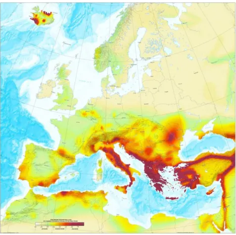
Figure 1 Seismic hazard map of Europe for 2003 (Source: European seismological Commission) ... 2
Figure 2 The components of seismic risk assessment and choices for the vulnerability assessment procedure [4] ... 3
Figure 3 Exploded view of the studied ductile anchor plate connection (Drawing from STAP company) ... 4
Figure 4 Simplified representation of the energy path and of the filtering effect of masonry buildings on the ground acceleration to walls responding out-of-plane [5] ... 5
Figure 5 Out-of-plane mechanism observed in unretrofitted buildings [7] ... 7
Figure 6 Improvement of perpendicular walls connectivity [12] ... 10
Figure 7 Alternative solutions to connect stiff diagram to masonry walls [8] ... 10
Figure 8 Deformed shape of an element under simple compression [16] ... 11
Figure 9 Representation of both yield conditions in the principal stress plane ... 12
Figure 10 Change of effective length of a beam under deformation [15] ... 13
Figure 11 Non linear solution procedures. a)Forward Euler method, b)Newton-Raphson method, c) Modified Newton-Raphson method. ... 14
Figure 12 Deformed shape of an isolated building [21] ... 15
Figure 13 Frequency range of both normal and isolated structures compared to the seismic action [21] ... 15
Figure 14 Behaviour of a hysteretic dissipater with its cycle area representing the dissipated energy. 16 Figure 15 Dissipative connection a) Precast concrete hybrid connection, b) Decomposition of the flag shape hysteresis [22] ... 17
Figure 16 Strengthening of Chiesa of San Giorgio in Trignano ... 17
Figure 17 General view of the ductile anchor plate ... 19
Figure 18 Dimensions of the ductile anchor plate ... 20
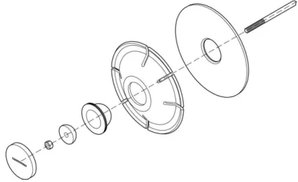
Figure 19 Exploded view of the ductile anchor connection ... 21
Figure 20 Cross section of a retrofitted masonry wall with a ductile anchor plate ... 21
Figure 21 Final geometry ... 23
Figure 22 CHX60 element a) Overview of the element b) Basic variables ... 24
Figure 23 CQ48I element a) Overview of the element b) Basic variables ... 24
Figure 24 Detail on the two layers of elements in the thickness of the plate ... 25
Figure 25 Detail on the mesh quality test ... 26
Figure 26 Nodal principal stress P1 for model 1 ... 26
Figure 27 Detail on the mesh quality test ... 26
Figure 28 Nodal principal stress P1 for model 2 ... 26
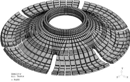
Figure 29 General view of the shrunken mesh of the ductile anchor plate ... 27
Ductile connection characterization regarding seismic retrofitting of masonry buildings
Erasmus Mundus Programme xviii ADVANCED MASTERS IN STRUCTURAL ANALYSIS OF MONUMENTS AND HISTORICAL CONSTRUCTIONS
Figure 32 Vertical displacements plotted on the deformed shape ... 31
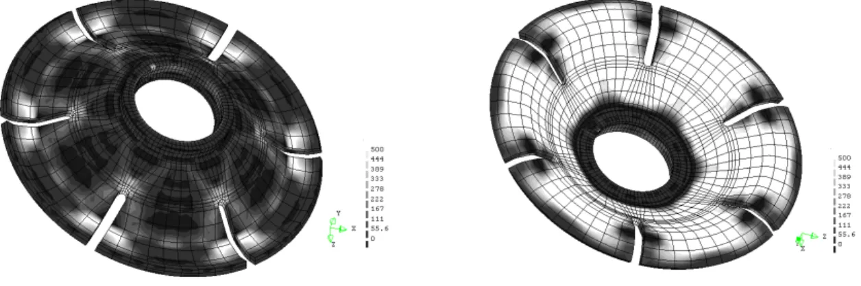
Figure 33 Top and bottom view of deformed plate with principal stress 1 from 0 to 500MPa ... 32
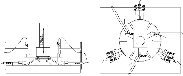
Figure 34 Measurement set-up ... 34
Figure 35 General view of the testing machine and zoom on the hydraulic jack. ... 34
Figure 36 Specimen preparation: a) surface sanding, b) numeration, c) geometry ... 36
Figure 37 Cyclic procedure represented in terms of displacement and duration. ... 37
Figure 38 Overview of the deformed shape (left before loading, right after loading) ... 38
Figure 39 Separation phenomenon a) Crushed corners b) Bottom Curve c) Waves on top ring ... 38
Figure 40 Yielding phenomenon a) Micro cracks b) Propagated crack with yielding area c) Global behaviour ... 39
Figure 41 Force-displacement relationship of the specimen DP6 tested under a monotonic load ... 40
Figure 42 Force-displacement relationship of the plate DP1 under a cyclic load ... 41
Figure 43 Cyclic response of the plate DP2, DP3, DP5 and DP7 ... 42
Figure 44 Study of the drop of force (left: zoom on the drop, right: trend lines of the three behaviours) ... 43
Figure 45 Envelope curves of all graphs Force versus Displacement ... 44
Figure 46 Slopes of the trend lines corresponding to the loading stiffness ... 45
Figure 47 Stiffness degradation related to the displacement reached for each cycle ... 46
Figure 48 Detail of the expected contact area modelled with contact elements. ... 48
Figure 49 Detail of the expected contact area modelled with interface elements. ... 49
Figure 50 View of the final boundary conditions. ... 49
Figure 51 Evolution of the model behaviour during the first calibration steps. ... 50
Figure 52 First parametric method analysing the fitting of the numerical results in the experimental envelope. ... 52
Figure 53 Second parametric method linking relative errors between numerical and experimental results with variables of the parametric study... 52
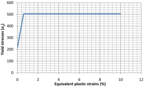
Figure 54 Stress - equivalent plastic strains relationship. ... 53
Figure 55 Principal stresses on deformed shape with magnification factor equal to 1: a) Top and bottom view of P1 plotted from 0 to 550 MPa; and b) Top and bottom view of P3 plotted from -550 MPa to 0. ... 54
Figure 56 Von misses stresses plotted from 0 to 550 MPa on deformed shape with magnification factor equal to 1 (top and bottom view). ... 54
Figure 57 Stiffness degradation during numerical cyclic test. ... 55
Figure 58 Comparison of deformed shapes: a) Experimental deformed shape; and b) Numerical deformed shape with vertical displacements. ... 56
Figure 59 Comparison of crack location; a) Experimental crack in opening, and b) Principal stresses P1 in opening. ... 57
Figure 60 Comparison of support: a) Experimental crushed support; and b) Principal stresses P3 on modelled support. ... 57 Figure 61 Comparison of the top of the plate: a) Experimental deformed shape; b) Principal stresses P3 top view of the hole; c) Principal stresses P3 bottom view; and d) Principal stresses P1 bottom view. ... 58 Figure 62 Comparison of the numerical and experimental response under monotonic load... 58 Figure 63 Numerical and experimental response of the plate under cyclic loading ... 59 Figure 64 Comparison of the numerical and experimental stiffness degradation ... 60 Figure 65 Comparison between the end of a numerical and experimental cycle. ... 61 Figure 66 Electrical analogy of the ductile system ... 65 Figure 67 Force-Displacement diagram for each element and the global connection ... 65 Figure 68 Expected flag hysteresis response. ... 67 Figure 69 Proposed improvements of the ductile anchor ... 67 Figure 70 Proposed improvement n°2 ... 68 Figure 71 location of measured dimensions ... 73 Figure 72 Summary of specimens dimensions (DP1 to DP7) ... 74 Figure 73 Sumary of specimens dimensions (DP8 to DP12) ... 75 Figure 74 History of the cyclic loading procedure ... 76 Figure 75 Cyclic response of the specimens with stiffness degradation a)DP1 b)DP2 c)DP3 d)DP5 .. 78
LIST OF TABLES
Table 1 Summary of stiffness with average and standard deviation... 45 Table 2 Summary of stiffness degradation expressed in percentage. ... 55 Table 3 Summary of dimensions and stiffness for different type of steel ties ... 64
CHAPTER 1: INTRODUCTION
1 SEISMIC VULNERABILITY
1.1 Related notions and definitions
Seismic vulnerability is highly related to seismic risk. The seismic risk is defined as the expected amount of damage for a given place, sustained by objects, buildings and people as a consequence of a seismic event [1]. It can be divided into three factors: hazard, exposure and vulnerability. In [2], the authors relate these factors through the equation 1
risk = hazard × vulnerability × exposure (1)
We define the seismic hazard for a given area as the ground motion expected within a given time period. More precisely, the seismic hazard is the probability of occurrence of this ground shaking. The most common parameter to express the excitation is the maximum peak of the ground horizontal acceleration. It is the first step in the evaluation of seismic risk.
The calculation for seismic hazard involves different aspects such as the regional geology and seismology or mathematical expressions. The final result provides a probability of exceeding a value (usually the peak ground acceleration) within a time interval as shown on Figure 1.
The exposure corresponds to the estimation of the quantity, quality and value of all casualtie and injury to individuals, economic cost related to repair works or loss of cultural heritage associated to the seismic action. This notion is therefore closely connected to the distribution, structure and socio-economic system of a whole community [1].
The last factor that appears in the seismic risk formulation is the seismic vulnerability which is linked to the scope of this study.
A qualitative definition of this concept is presented in [3] as “the proneness of some category of elements at risk to undergo adverse effects inflicted by potential earthquakes”. Applied to a building, the seismic vulnerability corresponds to its behaviour described via a cause-effect law, where the cause is the earthquake and the effect is the damage [1]. This concept will be developed in the following subparts.
Ductile connection characterization regarding seismic retrofitting of masonry buildings
Erasmus Mundus Programme 2 ADVANCED MASTERS IN STRUCTURAL ANALYSIS OF MONUMENTS AND HISTORICAL CONSTRUCTIONS
Figure 1 Seismic hazard map of Europe for 2003 (Source: European seismological Commission)
1.2 Assessment methodology
Seismic vulnerability assessment aims to characterize the seismic demand of the earthquake on the building which means the assessment needs to be carried out for a particular characterization of the ground motion. Traditionally, the analyzed parameter was related to macroseismic intensity or peak ground acceleration (PGA), whereas nowadays the vulnerability of a building is more commonly linked to response spectra obtained from past ground motions.
Figure 2 summarizes the various methods for vulnerability assessment that have been proposed in the past for use in loss evaluation. According to [4], we can divide them into two main categories: empirical or analytical, which can both be used in the hybrid method.
Empirical methods, which can also be called “damage-motion relationships”, are based on the damage observed after earthquakes and could be separated into two main types:
• Damage probability matrices (DPM), which express a conditional probability of obtaining a damage level (j) due to a ground motion of intensity (i) in a discrete form; this traditional assessment method is represented with a bold path on Figure 2.
• Vulnerability functions, which express the probability of exceeding a given damage state, given a function of the earthquake intensity, by means of continuous functions.
On the other hand, analytical methods relate post-earthquake damage statistics to limit-state mechanical properties of the buildings and appear to present more detailed and clearer vulnerability assessment algorithms with direct physical meaning. These characteristics, which are a real disadvantage for empirical methods, are very useful in studies such as parametric studies with retrofitting purposes for example. The development of these analytical methods is mainly due to the emergence of seismic hazard expressed in terms of response spectra obtained from ground motions.
Figure 2 The components of seismic risk assessment and choices for the vulnerability assessment procedure [4]
In this way, it is of great importance to understand how a structure behaves under seismic actions not only in its present state but also with the influence of retrofitting initiatives. The more the behaviour is understood the more the model will be accurate and then the more the risk and loss assessment will be explicit and relevant.
Ductile connection characterization regarding seismic retrofitting of masonry buildings
Erasmus Mundus Programme 4 ADVANCED MASTERS IN STRUCTURAL ANALYSIS OF MONUMENTS AND HISTORICAL CONSTRUCTIONS
2 DESCRIPTION OF THE TOPIC
This dissertation deals with masonry and timber connections between horizontal diaphragms (floors, roofs) and vertical structural elements (walls) in the scope of a seismic retrofitting of historical constructions.
It focuses on a specific type of innovative connection, more particularly a ductile anchor plate for steel tie rods or timber beams anchorage which is designed to dissipate energy in case of a hypothetical seismic action.
Figure 3 Exploded view of the studied ductile anchor plate connection (Drawing from STAP company)
3 MOTIVATIONS
The latest earthquakes show once again how important connections are between structural elements regarding seismic vulnerability.
Horizontal structural members affect the overall deformability of the structure and the distribution of seismic actions among (according to their in-plane stiffness) and across (according to the boundary conditions) the vertical structural elements. Absence of efficient connections between these structural elements is one of the main reasons for high vulnerability of historical masonry buildings regarding seismic actions.
This deficiency leads to out of plane deformation and then collapse of perimeter walls which is a principal cause of failure in most traditional forms of masonry construction and constitutes the most serious life-safety hazard for this category of building [5].
A schematic representation of the load path in Figure 4 shows that seismic response of structural elements and consequently global behaviour is highly influenced by the energy path which can be disrupted because of deficient connections.
Figure 4 Simplified representation of the energy path and of the filtering effect of masonry buildings on the ground acceleration to walls responding out-of-plane [5]
Despite this important issue regarding seismic performance of masonry buildings, this field has been poorly investigated and more research needs to be done.
4 AIMS
The first objectives of the present study are to understand the seismic response of this structural connection and to demonstrate its contribution and efficiency in comparison with a classical tie rod connection.
If the results show that it really works as an efficient dissipative device, the intended goal is to characterize quantitatively the ductile connection by mean of a stiffness value that could be implemented in a global numerical model of a building.
Such a characterisation of the connection should give more accurate results regarding seismic vulnerability assessment of historical constructions and help engineers and architects to design the appropriate retrofitting method. As it has been said previously, it is highly important to understand both local and global behaviour of a construction in a life-safety hazard analysis.
Finally, a secondary objective is to think about possible improvements that could be made to the anchor plate so this method would become more competitive against other retrofitting techniques.
Ductile connection characterization regarding seismic retrofitting of masonry buildings
Erasmus Mundus Programme 6 ADVANCED MASTERS IN STRUCTURAL ANALYSIS OF MONUMENTS AND HISTORICAL CONSTRUCTIONS
5 ORGANIZATION OF THE DOCUMENT
The present dissertation is structured in height chapters.
Chapter 1 recalls some background theory about seismic vulnerability in order to point out the global field of the present study and to show the importance of numerical models in nowadays seismic vulnerability assessment. As an introductive chapter, it also describes the topic and defines the objectives and motivations of it.
Chapter 2 presents a state of the art concerning the out of plane failure mechanism in historical buildings subjected to earthquakes and both traditional and innovative seismic retrofitting techniques which can be used to tackle this problem, focusing on the passive protection devices. The literature of non linear numerical analysis applied to FEM is also reviewed.
Chapter 3 introduces the plate by describing the prototype in a qualitative and quantitative way and defines the main expectations of this innovative connection.
Chapter 4 focuses on the main work of the present study which was the numerical analysis of the ductile plate. The preliminary model is fully described and the analysis results are discussed in order to provide a bench mark for the experimental part.
Chapter 5 describes the experimental campaign carried out. The elaboration of the test set-up and the development of the procedure done without any standards are explained and all the experimental results are analysed and discussed by paying attention to the seismic response of the plate.
Chapter 6 explains the calibration process leading to a better matching of the numerical and experimental results. After this comparison and the model update, the final results of the plate are analysed in depth and discussed.
Chapter 7 Analyses the global seismic response of the plate regarding to its connected elements and concludes on how the plate could be improved.
Chapter 8 presents the conclusions and recommendations for further work on this type of ductile connection. An improvement of the plate regarding its seismic response is also proposed.
CHAPTER 2:
SEISMIC
RETROFITTING
OF
HISTORICAL CONSTRUCTION
1 INTRODUCTION
1.1 Out of plane behaviour of masonry walls
The out of plane behaviour of masonry walls has been pointed out in several papers as very likely to occur during an earthquake excitation.
Ramos and Lourenço assessed through finite element analyses that the most observed failure mechanisms of ancient masonry buildings due to seismic actions appeared to be the overturning of the perimeter walls [6]. They made the conclusions that in cases where safety against seismic actions was clearly insufficient, owners and regulators must address the issue of retrofitting these structures. They also advised to tie the buildings with steel rods or to strengthen the timber floors, especially taking into account the connections with masonry walls.
Valluzi and Modena confirmed this issue through post-earthquake damage assessment [7]. Their literature review showed that the previous seismic events in Italy, particularly the one in Umbria in 1997 presenting a moderate magnitude (5.6 Richter magnitude scale), led on a large scale to brittle out-of-plane mechanisms of collapses (partial or global overturning of facades or corners) in buildings (Figure 5).
Ductile connection characterization regarding seismic retrofitting of masonry buildings
Erasmus Mundus Programme 8 ADVANCED MASTERS IN STRUCTURAL ANALYSIS OF MONUMENTS AND HISTORICAL CONSTRUCTIONS
1.2 Important concepts in seismic retrofitting strategies
Seismic retrofitting could be defined as the modification of structures to make them more resistant to earthquake hazard. Seismic retrofit can be achieved by means of appropriate strengthening but alternative strategies can also improve the seismic behaviour of a structure.
1.2.1 Energy dissipation
During a seismic event, part of the kinetic energy provided to the structural system by the earthquake is dissipated by means of frictional forces or structural yielding such as hysteresis which is a form of energy dissipation related to the inelastic deformation of the structure [8].
When a structure is undergoing a seismic excitation, it will amplify the base ground motion according to its ability to dissipate the energy of the earthquake ground-shaking. Regarding masonry buildings, the energy is normally dissipated thanks to friction at the mortar joint interfaces or mortar beddings cracking. This physical notion is very important in seismic retrofitting and it is often that engineers and architects do not pay sufficient attention to it.
1.2.2 Ductility
[2] defines this notion in the context of seismic design as the ability to dissipate energy by developing an inelastic response under high-amplitude cyclic deformations without experiencing a significant loss in load carrying capacity. This important concept does not characterize unreinforced masonry because of the poor bonding strength at the unit-mortar interface. As a brittle material under tension, its lateral resisting capacity is highly affected after the initial damage.
1.2.3 Structural stiffening
Some structures present a weak seismic behaviour because structural elements do not have appropriate ductility or toughness to resist the large lateral deformations induced by the earthquake. Stiffening the structure aims at increasing the seismic performance by reducing lateral deformation. [9] presents different measures to effectively add stiffness to an existing structure such as the construction of new braced frames or shear walls.
1.2.4 Structural strengthening
Structural strengthening is needed is structures presenting an inadequate strength to resist lateral forces explained physically by an inelastic behaviour at very low levels of ground shaking. Adding strength to weak lateral-force-resisting system aims to raise the threshold of ground motion at which damages start to occur.
1.3 Connections
1.3.1 Importance of connections in URM buildings
Most of the time researches focus on structural components like masonry walls or floor and roof diaphragms but rarely on connections between them.
Wall-diaphragm connections can significantly influence the seismic behaviour of unreinforced masonry buildings. Failure of the connections could be the cause for a global structural collapse and their ductility could act on the overall structural response [10].
However, wall diaphragm connections for URM buildings haven’t been deeply studied leading to a lack of data on inelastic force–displacement behaviour of wall-diaphragm connections. Force-displacement behaviour, in other words the stiffness values of the connection, could be useful information in order to carry out a numerical analysis of an entire building. One of the main conclusions of [11] is that connections in URM structures affect the overall response of the structure. Therefore, models describing the joist bearing connections should be developed and applied to retrofit designs. They also developed a method to implement dynamic friction behaviour in finite-element models. Friction contributes to the energy dissipation during a seismic event and could avoid a global collapse of a structure.
1.3.2 Main connection types
One of the solutions to increase seismic performance of masonry load-bearing systems is to improve the connectivity between the principal structural members (perpendicular walls and floor diaphragms). However, improving their connectivity does not lead to either a significant alteration or an important increase of the stiffness of the building. Traditional devices such as anchors or ties are used to improve the connectivity which aims to preserve or even increase the ductility of the retrofitted structure thanks to their flexibility.
At a global level, the main improvements of connectivity focus on intersecting wall connections and wall to horizontal diaphragm connections.
Perpendicular walls can present a particularly weak connection due to cracks present on interlocking bricks bounding and improving their connectivity could lead to a seismic behaviour improvement of the whole structure. An example of retrofitted structure by mean of steel ties is presented in Figure 6. Ties can be positioned in channels cut in the masonry and covered by plaster to be protected from corrosion and both ends are usually anchored with steel bearing plates [8].
Ductile connection characterization regarding seismic retrofitting of masonry buildings
Erasmus Mundus Programme 10 ADVANCED MASTERS IN STRUCTURAL ANALYSIS OF MONUMENTS AND HISTORICAL CONSTRUCTIONS
Figure 6 Improvement of perpendicular walls connectivity [12]
Tomazevic et al. (1996) confirmed through an experimental campaign that seismic behaviour of historic masonry houses were depending on the rigidity of floors and connection of walls. They showed that ties prevented out of plane vibration of the wall. They also indicated that lateral load-resistance and deformability, as well as energy dissipation capacity were significantly improved. The comparison of test results pointed out that 2.5-times more input energy was needed to cause the collapse of retrofitted model with steel ties than in the case of the reference model [13].
Another connectivity improvement affecting masonry walls stabilisation and consequently the global seismic behaviour of a structure can be done on walls to floor diaphragms connections. The target is to prevent out-of-plane instability of masonry walls during an earthquake by improving the seismic load distribution through a stiff floor diaphragm. For this purpose, improvement of connectivity may not be sufficient if the floor is not stiff enough. In this case, stiffening of the diaphragm can be carried out by, for example, adding an extra layer of wooden planks on top of the existing floor. Illustrations of alternative solutions for this type of connectivity improvement are given in Figure 7.
Figure 7 Alternative solutions to connect stiff diagram to masonry walls [8]
1.3.3 Ductile connection design
A state of the art of in connection seismic design is given in [14]. This paper analyses some experimental results concerning rigid or semi-rigid connection in different types of structures mainly steel frames. His first assumption in connection design is that a ductile mechanism in connection or close to it must have a lower resistance than any potential failure mechanism which is brittle or has low ductility in order that the ductile zone will yield before the weak or brittle area. He mentioned another important thing saying that local dissipative devices can provide a stable energy dissipation if their force-displacement relationship is characterized by stable loops.
2 NON LINEAR ANALYSIS OF A STEEL DUCTILE CONNECTION
Design and validation of possible retrofitting techniques can be done through structural modelling by simulating their effect on an accurate numerical model of the structure. Moreover, the analysis of the retrofitted building requires, in particular, the modelling of the retrofitting techniques implemented. Numerical results will then lead to an accurate seismic vulnerability assessment and as a consequence reduce the life-safety hazard.
2.1 Parameters affecting the non-linearity
During a numerical analysis, attention has to be paid to the amount of displacement which occurrs during the loading phase because it will affect the type of analysis. The reason for this is that the stiffness of a structure will be affected by the deformations occurring under a load. If the displacements are small enough which means that the stiffness will not be much affected by the deformation, the analysis can be considered as linear. On the other hand, for higher displacements, several parameters such as shape, material properties or supports can significantly change the stiffness of the structure and, as a consequence, conduct to a nonlinear analysis.
2.1.1 Geometrical non-linearity
Geometrical non linearity refers to the change of stiffness of a structure under a load due to its change of shape. If the deformation is important, the initial configuration might no longer be valid to express equilibrium and compatibility (Figure 8). Moreover, under large deformations, the load direction could change as the structure will deform, depending on the reference coordinate system. Usually, finite element analysis programmes present the choice of following or non-following load.
An accepted rule for the use of a geometrically non liner analysis is given in [15]. It is advised that such an analysis should be used if the ratio of a structure deformation and its largest dimension is greater than 1/20th.
Figure 8 Deformed shape of an element under simple compression [16]
2.1.2 Physical non linearity
Another type of non-linearity analysis is required when the loads are high enough to cause some irreversible deformations to a structure or damage (e.g. cracks). The elastic limit of the material is
Ductile connection characterization regarding seismic retrofitting of masonry buildings
Erasmus Mundus Programme 12 ADVANCED MASTERS IN STRUCTURAL ANALYSIS OF MONUMENTS AND HISTORICAL CONSTRUCTIONS
Analysis (FEA) programs have developed specialized techniques and material models to simulate these behaviours. Regarding metals, two material models can be used: Von Mises or Tresca model. The Von Mises model assumes that plastic yielding starts when the elastic energy stored in changes of shape reaches a critical value (Equation 3) whereas the Tresca model is based on the fact that plastic yielding begins when the shear stress on any plane in any direction reaches a critical value (Equation 2) [17]. These two models are shown in Figure 9 in the case of plane stress. The Tresca condition is represented by the six faces of the failure criterion degenerated into lines. The Von Mises condition degenerates into an ellipse passing through the segment intersections which defines the Tresca condition. The intersection of the yield criteria and the axes σ1 and σ2 correspond to the uniaxial tensile and compression resistances [16]. According to [18] the Von Mises elasto-plasticity is by far the most widely used plasticity model.
Equation 2 Mathematical formulation of Tresca model
Equation 3 Mathematical formulation of Von Mises model
Figure 9 Representation of both yield conditions in the principal stress plane
2.1.3 Contact non-linearity
Changing of the contact or support condition can also modify the stiffness of a structure. This can be easily understood with the practical example shown in Figure 10 where the stiffness is highly affected by the drop of the beam effective length. High attention should be paid to these contact areas. Modelling them should be done by means of contact or interface elements instead of normal supports so that the interacting surfaces can change during the deformation of the structure. These elements are often used and recommended in order to model areas such as bolt and washer or hole for example [19].
Figure 10 Change of effective length of a beam under deformation The effectiveness of contact elements was demonstrated in
carried out as well as an analytical analysis and an experimental campaign concerning innovative dissipative connections (INERD). One of their observations on the graph representing numerical results versus experimental ones is that contact element analysis describes i
connection response than the gap element analysis.
2.2 Numerical non-linear solution procedures
The non linear solution procedures are very important in the way that they define the solution in terms of accuracy compared to the real solution
2.2.1 Types of non
A first solution procedure is based on an increment method. This method called Forward the stiffness matrix from the previous load increment in order to calculate the
(Figure 11a) which could lead to
Another solution procedure, the Newton
improved by using an iteration procedure. In this case, for the sam
displacement is calculated after several iterations modifying the stiffness until the convergence criterion is fulfilled (Figure 11b).
The last method is called the M
from the Newton-Raphson method but keeps the same stiffness during each load increment instead of modifying it after each iteration (
According to [17], in terms of accuracy, convergence but each iteration is quite
Raphson method leads to a slower convergence but the iterations are
Change of effective length of a beam under deformation
The effectiveness of contact elements was demonstrated in [20]; in which different FEM analysis were s well as an analytical analysis and an experimental campaign concerning innovative dissipative connections (INERD). One of their observations on the graph representing numerical results versus experimental ones is that contact element analysis describes i
connection response than the gap element analysis.
linear solution procedures
The non linear solution procedures are very important in the way that they define the solution in terms of accuracy compared to the real solution and also the time consumption of the analysis.
Types of non-linear procedures
A first solution procedure is based on an increment method. This method called Forward from the previous load increment in order to calculate the
lead to an important error.
Another solution procedure, the Newton-Raphson method, is based on the same concept but was improved by using an iteration procedure. In this case, for the same increment of load, the displacement is calculated after several iterations modifying the stiffness until the convergence
b).
called the Modified Newton-Raphson method. As its name indicates
Raphson method but keeps the same stiffness during each load increment instead of modifying it after each iteration (Figure 11c).
, in terms of accuracy, the Newton-Raphson method usually implies a fast convergence but each iteration is quite time consuming. On the other hand, the M
Raphson method leads to a slower convergence but the iterations are faster.
Change of effective length of a beam under deformation [15]
; in which different FEM analysis were s well as an analytical analysis and an experimental campaign concerning innovative dissipative connections (INERD). One of their observations on the graph representing numerical results versus experimental ones is that contact element analysis describes in a better way the
The non linear solution procedures are very important in the way that they define the solution in terms and also the time consumption of the analysis.
A first solution procedure is based on an increment method. This method called Forward Euler uses from the previous load increment in order to calculate the new displacement
Raphson method, is based on the same concept but was e increment of load, the displacement is calculated after several iterations modifying the stiffness until the convergence
name indicates, it follows on Raphson method but keeps the same stiffness during each load increment instead of
Raphson method usually implies a fast time consuming. On the other hand, the Modified
Newton-Ductile connection characterization regarding seismic retrofitting of masonry buildings
14 ADVANCED MASTERS IN STRUCTURAL ANALYSIS OF MONUMENTS AND HISTORICAL CONSTRUCTIONS
Figure 11 Non linear solution procedures. a)Forward Euler method, b) Modified Newton
2.2.2 Line search
The iterative procedures aforementioned show a severe limitation by not being globally convergent but converging to a solution from almost any initial solution. To tackle this problem in structural analyses, the line search method is often used to find an e
convergence of the Newton-Raphson method
2.2.3 Convergence criteria
The convergence of the solution method implies the definition of one or several convergence criteria which allow to obtain the wanted solution with the precision wished. The convergence criteria are based on different Euclidian rules and can be divided into
defined by mean of displacements, forces or energy. The criterion corresponds to the maximum tolerance or error that could be admitted during the calculation to accept the solution
3 PASSIVE SEISMIC PROT
3.1 Base isolation devices
The concept of the base isolation aims at disconnecting a building from the horizon
the ground motion by mean of a device with a low horizontal stiffness inserted between the structure and its foundations. The horizontal displacements will then be increased but located at the base isolation level (Figure 12). Furthermore, the building will be subjected to a lower acceleration and will hardly undergo deformation behaving as a rigid body.
a) b)
Ductile connection characterization regarding seismic retrofitting of masonry buildings
Erasmus Mundus Programme ADVANCED MASTERS IN STRUCTURAL ANALYSIS OF MONUMENTS AND HISTORICAL CONSTRUCTIONS
Non linear solution procedures. a)Forward Euler method, b)Newton-Raphson method, c) Modified Newton-Raphson method.
he iterative procedures aforementioned show a severe limitation by not being globally convergent but converging to a solution from almost any initial solution. To tackle this problem in structural analyses, the line search method is often used to find an estimation of the solution outside of the radius of
Raphson method [16].
Convergence criteria
he convergence of the solution method implies the definition of one or several convergence criteria to obtain the wanted solution with the precision wished. The convergence criteria are based on different Euclidian rules and can be divided into three categories depending if the criterion is defined by mean of displacements, forces or energy. The criterion corresponds to the maximum tolerance or error that could be admitted during the calculation to accept the solution
PASSIVE SEISMIC PROTECTION DEVICES
Base isolation devices
The concept of the base isolation aims at disconnecting a building from the horizontal components of the ground motion by mean of a device with a low horizontal stiffness inserted between the structure and its foundations. The horizontal displacements will then be increased but located at the base ). Furthermore, the building will be subjected to a lower acceleration and will hardly undergo deformation behaving as a rigid body.
c) b)
Ductile connection characterization regarding seismic retrofitting of masonry buildings
Erasmus Mundus Programme ADVANCED MASTERS IN STRUCTURAL ANALYSIS OF MONUMENTS AND HISTORICAL CONSTRUCTIONS
Raphson method, c)
he iterative procedures aforementioned show a severe limitation by not being globally convergent but converging to a solution from almost any initial solution. To tackle this problem in structural analyses, stimation of the solution outside of the radius of
he convergence of the solution method implies the definition of one or several convergence criteria to obtain the wanted solution with the precision wished. The convergence criteria are three categories depending if the criterion is defined by mean of displacements, forces or energy. The criterion corresponds to the maximum tolerance or error that could be admitted during the calculation to accept the solution [16].
tal components of the ground motion by mean of a device with a low horizontal stiffness inserted between the structure and its foundations. The horizontal displacements will then be increased but located at the base ). Furthermore, the building will be subjected to a lower acceleration and will
Figure 12 Deformed shape of an isolated building [21]
As a direct consequence the natural frequency range of the building will be reduced. Moreover, isolated structures will also have frequencies lower than the frequencies with the highest energy content of the seismic actions (Figure 13). To be efficient the base isolation device needs to have a good support capacity, a low horizontal stiffness, and both appropriate capacities of energy dissipation and initial position restitution [21].
Figure 13 Frequency range of both normal and isolated structures compared to the seismic action [21]
3.2 Energy dissipation devices
Another seismic protection technique is energy dissipation, by means of devices helping the structure in dissipating the earthquake energy. These energy dissipaters are implemented in specific places of the building subjected to relative displacements in order to avoid the structure to dissipate the energy in an autonomous way. Several types of devices exist, the most common being the hysteretic dissipaters and the viscous dissipaters. These two systems have an easy implementation into the structural system and a versatility that favours their use.
3.2.1 Viscous dissipaters
This type of dissipaters works as a piston in which the fluid laminates from one chamber to the other and at the same time dissipates energy. The force-velocity relation will essentially depend on the characteristics of the fluid as shown in the generalized expression (4) taken from [21]
F = C|v| sin v (4)
Ductile connection characterization regarding seismic retrofitting of masonry buildings
16 ADVANCED MASTERS IN STRUCTURAL ANALYSIS OF MONUMENTS AND HISTORICAL CONSTRUCTIONS
3.2.2 Hysteretic dissipaters
In the case of hysteretic dissipaters, the energy dissipation happens through the plasticization of the metallic element which is usually steel or through friction of its components. The force will depend on the deformation imposed and the device will be defined by an initial stiffness K
K2 and a yield strength FT presented in
the internal area on the graph relating the force and the deformation of the device for each cycle.
Figure 14 Behaviour of a hysteretic dissipater
Research has been done in the field of innovative hysteretic dissipaters especially in moment frame connections like the new jointed timber structural system for post
in [22]. Newcombe carried out an experimental campaign on jointed ductile connections concluded by giving guidelines that enable a complet
The concept of post-tensionned connection he studied was elaborated in 2004 Canterbury, New Zealand [23] but the
existing precast concrete techniques developed ductile connection shown in Figure
tensioned tendons allow a self
reinforcements deform inelastically and thus dissipate energy. These two features of the connection lead to a flag shape hysteresis behaviour shown in
Ductile connection characterization regarding seismic retrofitting of masonry buildings
Erasmus Mundus Programme ADVANCED MASTERS IN STRUCTURAL ANALYSIS OF MONUMENTS AND HISTORICAL CONSTRUCTIONS
Hysteretic dissipaters
In the case of hysteretic dissipaters, the energy dissipation happens through the plasticization of the hich is usually steel or through friction of its components. The force will depend on the deformation imposed and the device will be defined by an initial stiffness K1, a post
presented in Figure 14. The dissipated energy can be found by calculating the internal area on the graph relating the force and the deformation of the device for each cycle.
Behaviour of a hysteretic dissipater with its cycle area representing the dissipated energy. been done in the field of innovative hysteretic dissipaters especially in moment frame
jointed timber structural system for post-tensioned timber buildings presen combe carried out an experimental campaign on jointed ductile connections by giving guidelines that enable a complete design of post-tensioned timber frame systems
tensionned connection he studied was elaborated in 2004 at the
but the idea of the hybrid connection was conceived based on the existing precast concrete techniques developed at the University of San Diego [24]
Figure 15a was designed so that under a seismic excitation post a self-centering capacity while remaining elastic and mild steel reinforcements deform inelastically and thus dissipate energy. These two features of the connection lead to a flag shape hysteresis behaviour shown in Figure 15b.
Ductile connection characterization regarding seismic retrofitting of masonry buildings
Erasmus Mundus Programme ADVANCED MASTERS IN STRUCTURAL ANALYSIS OF MONUMENTS AND HISTORICAL CONSTRUCTIONS
In the case of hysteretic dissipaters, the energy dissipation happens through the plasticization of the hich is usually steel or through friction of its components. The force will depend on , a post-yield stiffness dissipated energy can be found by calculating the internal area on the graph relating the force and the deformation of the device for each cycle.
with its cycle area representing the dissipated energy. been done in the field of innovative hysteretic dissipaters especially in moment frame
tensioned timber buildings presented combe carried out an experimental campaign on jointed ductile connections and tensioned timber frame systems. at the University of idea of the hybrid connection was conceived based on the [24] [25] [26]. This that under a seismic excitation post-centering capacity while remaining elastic and mild steel reinforcements deform inelastically and thus dissipate energy. These two features of the connection
Figure 15 Dissipative connection
3.3 Shape memory alloys
Shape memory alloy devices (SMA) are usually made of an alloy of Nikel and Titanium which are known for their super-elasticity. The dissipation concept is based on the peculiar properties of their material. SMA can undergo importan
without plastification of the material nor significant degradation. Furthermore, their great elasticity allows an ecellent recentring of the strenghtenned structures.
As an example, this technique was applied to the bell tower of San Giorgio in Trignano after it ha been seriously damaged during the 1996 Modena and Reggio Emilia earthquake. We can see on Figure 16 that four SMA anchoring ties were applied to the structur
[27].
Figure 16
Dissipative connection a) Precast concrete hybrid connection, b) Decomposition of the flag shape hysteresis [22]
Shape memory alloys
Shape memory alloy devices (SMA) are usually made of an alloy of Nikel and Titanium which are elasticity. The dissipation concept is based on the peculiar properties of their material. SMA can undergo important deformation cycles through which they will dissipate energy without plastification of the material nor significant degradation. Furthermore, their great elasticity allows an ecellent recentring of the strenghtenned structures.
ue was applied to the bell tower of San Giorgio in Trignano after it ha been seriously damaged during the 1996 Modena and Reggio Emilia earthquake. We can see on
that four SMA anchoring ties were applied to the structure, increasing its flexural streng
16 Strengthening of Chiesa of San Giorgio in Trignano
a) Precast concrete hybrid connection, b) Decomposition of the flag
Shape memory alloy devices (SMA) are usually made of an alloy of Nikel and Titanium which are elasticity. The dissipation concept is based on the peculiar properties of their t deformation cycles through which they will dissipate energy without plastification of the material nor significant degradation. Furthermore, their great elasticity
ue was applied to the bell tower of San Giorgio in Trignano after it had been seriously damaged during the 1996 Modena and Reggio Emilia earthquake. We can see on e, increasing its flexural strength
CHAPTER 3: THE DUCTILE PLATE CONNECTION
1 PRESENTATION OF THE PLATE
1.1 Generalities
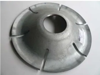
The innovative connection (Figure 17) analysed in this thesis is based on the traditional anchor plates for tie rods used world widely in most historical buildings with the difference that this ductile plate is designed not only to transfer loads but also to dissipate energy. This concept was brought to light in the NIKER project.
Figure 17 General view of the ductile anchor plate
1.2 NIKER project
The NIKER project is a European project involving both universities and companies dealing with the issue of damages on cultural heritage caused by earthquakes. It aims at complementing and enhancing traditional materials with innovative processes and developing new pioneering technologies. The main idea is that efficient protection of historical heritage should be achieved on the basis of the ‘minimum intervention’ approach.
The project is divided in 10 interactive work packages (WP) going from ‘project management (WP01) to ‘guidelines for end-users (WP10). The present study was introduced in WP06 named ‘connections and dissipative systems with early warning’ in which one of the objectives is to develop a hysteretic dissipation prototype [28]. A first prototype was made by the Portuguese company STAP and this dissertation aims at proving its efficiency and putting in place possible improvements.
Ductile connection characterization regarding seismic retrofitting of masonry buildings
Erasmus Mundus Programme 20 ADVANCED MASTERS IN STRUCTURAL ANALYSIS OF MONUMENTS AND HISTORICAL CONSTRUCTIONS
2 DESCRIPTION OF THE PLATE
2.1 General description
Instead of being a simple flat plate or even a single bar as in traditional connection, the ductile plate is circular and has a double curved shape with a uniform thickness of 6 mm as shown in Figure 18. It has an external diameter or 250 mm and an internal one of 65 mm. Moreover, six notches of 8 mm wide and 50 mm long are symmetrically disposed every 60° in order to allow the plate to deform and, as a consequence, dissipate energy. We also observe that the external outline is slightly curved toward the top so that the anchor doesn’t penetrate the support and keeps sliding and deforming during the cycles of the earthquake excitation. The dimensions are summarized in Figure 18 and they were confirmed during the experimental campaign.
Figure 18 Dimensions of the ductile anchor plate
2.2 Connection system
The exploded view in Figure 19 shows how the connection will be implemented during the seismic retrofitting of the building. The first flat plate (2) aims at supporting the ductile plate (3) with a smooth and strong surface in order to avoid crushing of the masonry before deformation of the connection. Then a system of full and hollow half-sphere (4) transfers forces from the tie rod (1) to the top of the ductile plate which allows the tie rod (1) to have a small rotation and helps the anchor plate (3) to be centre. Finally the tie rod (1) is screwed to a nut (5) and a cup (6) covers the fixation system to protect it and to give an attractive appearance to the whole connection knowing that aesthetic value has also to be preserved in the scope of the conservation of cultural heritage. Once installed, the tie rod can be anchored and pre-stressed in order to confine the structural elements connected (Figure 20)
65 86 3 6 250 R4 Ø147 8 60
![Figure 2 The components of seismic risk assessment and choices for the vulnerability assessment procedure [4]](https://thumb-eu.123doks.com/thumbv2/123dok_br/17917018.850101/28.892.181.702.305.915/figure-components-seismic-assessment-choices-vulnerability-assessment-procedure.webp)
![Figure 4 Simplified representation of the energy path and of the filtering effect of masonry buildings on the ground acceleration to walls responding out-of-plane [5]](https://thumb-eu.123doks.com/thumbv2/123dok_br/17917018.850101/30.892.143.746.139.514/figure-simplified-representation-filtering-masonry-buildings-acceleration-responding.webp)
![Figure 5 Out-of-plane mechanism observed in unretrofitted buildings [7]](https://thumb-eu.123doks.com/thumbv2/123dok_br/17917018.850101/32.892.166.746.715.966/figure-plane-mechanism-observed-unretrofitted-buildings.webp)