UNIVERSIDADE DE LISBOA FACULDADE DE CIÊNCIAS DEPARTAMENTO DE FÍSICA
DESIGN OF AN ENDOVASCULAR MORCELLATOR FOR
THE SURGICAL TREATMENT OF EQUINE CUSHING’S
DISEASE
Inês Nunes Sousa
MESTRADO INTEGRADO EM ENGENHARIA BIOMÉDICA E BIOFÍSICA PERFIL EM ENGENHARIA CLÍNICA E INSTRUMENTAÇÃO MÉDICA
Dissertação orientada por: Prof. Doutor Hugo Ferreira
PhD Student Aimée Sakes 2018
Acknowledgements
I would first like to thank my thesis advisers and mentors Dr. Hugo Ferreira and Aimée Sakes. Their offices were always open whenever I ran into a trouble spot or had a question about my research or writing. Aimée consistently allowed this paper to be my own work, but steered me in the right the direction whenever she thought I needed it. Professor Hugo was always there for me and gave me the strength and the advice to follow my heart, either in his classes or in this research.
I would also like to thank the experts who gave me the information I needed for this research project and who where so eager to help: Professor Paul Breedveld from the Faculty Mechanical, Maritime & Materials Engineering of TU Delft and Professor Han van der Kolk from the Faculty of Veterinary Medicine of the University Utrecht. Last but not least, I want to give an extra special thanks to all my family, my boyfriend and all the amazing friends I met before and during this journey. Without you, this project wouldn’t have been fun or exciting as it was. Thank you for all your support and your guidance.
Abstract
Just like people, thanks to a better understanding of health and medical care, horses are living longer than ever. Illnesses that commonly plague aged horses are becoming more prevalent. In particular, the number of horses diagnosed with Cushing’s disease has increased over the last several years. Cushing’s disease is a serious condition of an excess of the steroid hormone cortisol in the blood level, due to an increase secre-tion of adrenocorticotropic hormone (ACTH), normally caused by a benign pituitary tumour. ACTH stimulates the adrenal glands to produce cortisol, commonly referred to as the stress hormone. Cushing’s disease it’s most common in older horses (18–23 years) and often compromises the immune system, causing them to be more prone to infections and other health problems. There’s a treatment to control and reduce the severity of the clinical signs using oral medication, but remove the pituitary gland by surgery, so far, has been technically impossible. Although medication can be used for the symptoms, it’s not a long-term solution as the tumour is still there. A medical instrument capable of removing unhealthy tissue from the pituitary gland could be a good approach and it’s the major focus of this project.
As minimal invasive procedure instruments are not able to reach the equine pituitary gland so far, a discovered endovascular path from a facial vein to the pituitary gland could be the solution. After a literature review to understand nowadays techniques, mechanical morcellators came up as simple, cheap and easy to use and manipulate. The focus of this thesis is to design and create a prototype of a new debulking structure to be used in a mechanical endovascular morcellator.
The developed prototype (Ø 5,2 mm) incorporates three components used for the debulking process: an outside tube, an inside tube to transport the debris and a debulking component, able to cut thought tissue using axial translation and axial rotation force directions. The debulking part is composed of two blades with opposite helicoidal shape. This device allows frontal cuts and full resection with minimal tissue deformation, without having to aspirate the debris. Additionally, it allows to cut tissue from flat surfaces. A handgrip was also designed to allow the assembly of the all prototype and a motor was added to allow rotation. This new debulking component design seems to be promising, and it can serve as a starting point for more research on endovascular morcellators or even other kinds of morcellators.
Keywords: Morcellator, horses, Cushing’s disease, pituitary adenoma, medical de-vices
Resumo
Tal como nos humanos, e devido principalmente ao desenvolvimento da medicina, a esperança média de vida dos cavalos tem vindo a aumentar. Doenças que maioritari-amente atingem cavalos com uma idade mais avançada, aparecem agora com mais frequência. Em particular, o número de cavalos com a doença de Cushing tem vindo a crescer nos últimos anos. Esta doença, também designada por disfunção da pars intermedia da glândula pituitária (PPID), é uma condição comum e grave causada por função neuroendócrina anormal em equinos adultos. Atualmente, pensa-se que a PPID afete mais de 20% dos equinos com 15 ou mais anos.
Em animais vertebrados, a hipófise encontra-se dividida em três lobos: pars nervosa, pars intermedia e pars distalis. A pars intermedia, constituída por uma população de melanotropos, compreende menos de 5% da hipófise e é neste lobo onde os cavalos com PPID apresentam uma neoplasia ou hiperplasia. A causa de PPID não se en-contra totalmente esclarecida, mas sabe-se que há perda de inibição dopaminérgica dos melanotropos da pars intermedia. É possível que a lesão seja um aparecimento espontâneo de uma neoplasia pituitária, mas, também é possível que o aumento da pars intermedia da glândula pituitária resulte da perda de inibição dopaminérgica, ou seja, de causa degenerativa devido ao envelhecimento.
Os melanotropos sintetizam uma hormona precursora de pro-opiomelanocortina (PO-MC). O processamento de POMC origina ACTH, uma hormona estimulante de melanócitos α (α MSH), β-endorfina (β-END), cortisol (por estimulação das glându-las suprarrenais), entre outros. Estas hormonas são reguladas pela libertação/inibição de dopamina pelo hipotálamo. Na presença desse neurotransmissor, a síntese de POMC diminui e, consequentemente, também a síntese das hormonas derivadas de POMC. Estas hormonas têm várias funções no organismo: regulação do metabolismo, obesidade, stress, inflamação e redução de dor. Devido à perda de inibição dopam-inérgica, as concentrações de ACTH e produtos derivados aumentam. Esta subida faz com que os cavalos fiquem mais suscetíveis a infeções por fungos, bactérias e parasitas, devido ao enfraquecimento do sistema imunitário, e aumenta a incidência de problemas de infertilidade. Como sinais clínicos, temos o crescimento anormal do pêlo, falha ou atraso na mudança do pêlo, depressão, perda de peso, abdómen pendu-lar, depósitos anormais de tecido adiposo, poliúria e polidipsia, infecções secundárias e laminite.
Em humanos, o tratamento indicado para esta doença é a remoção do tumor, que pode ser removido por três vias diferentes: nasal, craniana e septal. Maioritariamente, as cirurgias são feitas via transfenoidal, com uma pequena abertura no nariz ou no septo. A vantagem da utilização destas ao invés da via craniana é a não exposição do cérebro, reduzindo a complexidade da cirurgia e os riscos inerentes. No cavalo, o único tratamento para a doença de Cushing consiste em medicação oral porque, até ao momento, não há nenhum instrumento médico capaz de cirurgicamente remover o tumor. O tratamento de equinos com PPID pode ser difícil devido à idade do animal e à ocorrência frequente de outros diversos problemas e patologias. Entre os fármacos utilizados encontram-se agonistas da dopamina, como o mesilato de pergolide, an-tagonistas da serotonina e inibidores da esteroidogénese adrenal, como o trilostano. Atualmente, o medicamento de eleição é o mesilato de pergoline, um agonista da dopamina que ativa os recetores dopaminérgicos tipo 2 nos melanotropos da pars intermedia, levando à diminuição da produção de POMC e de péptidos derivados re-sponsáveis pelos sinais clínicos. No entanto, embora indicados para os sinais clínicos,
este medicamento não diminui o tumor existente na hipófise, que continua a ser um problema.
Usando as mesmas técnicas cirúrgicas que em humanos, seriam necessários instru-mentos longos e finos que fossem capazes de perfurar vários centímetros de osso. Esta abordagem não só constituiria uma cirurgia morosa e complexa, com uma longa recuperação, como a probabilidade de danificar tecidos saudáveis seria grande. Em 1986, foi descoberto um caminho específico nos equinos que permite chegar à hipófise através de veias e cavidades. Este caminho pode ser acedido através de uma veia superficial facial. Com esta descoberta, um novo paradigma para a remoção de tu-mores surgiu: usar um instrumento endovascular para permitisse navegar pelas veias e cavidades e remover o tumor. O objetivo deste projeto é desenhar a construir um protótipo de um instrumento que permita remover tumores da hipófise em cavalos, usando o caminho descrito, com um especial foco na componente de ressecção do instrumento.
A cirurgia minimamente invasiva (MIS), também chamada de Laparoscopia, é uma técnica pouco invasiva que tem por definição ser menos agressiva, condicionar menos dor e permitir uma recuperação pós-operatória mais rápida. Em humanos, esta téc-nica é usada principalmente em procedimentos cirúrgicos na cavidade abdominal e pélvica, sendo por vezes também usada em procedimentos cardiovasculares. Em Por-tugal, a primeira cirurgia ocorreu em 1991. Nestes procedimentos, uma pequena incisão é feita no paciente e um instrumento com pequeno diâmetro, e muitas vezes equipado de fibra ótica com uma câmara e uma fonte de luz, é inserido. Nos cavalos, depois de alguns estudos e medições, foi definido um diâmetro máximo de 5 mm para um instrumento ser inserido nos vasos sanguíneos. O instrumento tem de ser flexível, capaz de contornar cavidades e ossos e deve ter um comprimento mínimo de 350 mm. O componente de ressecção deverá constar no topo do instrumento e, para que o corte seja o mais estável possível, deverá ser rígido e não ter mais do que 14 mm de comprimento.
Foram precisos definir alguns requisitos essenciais para o design do instrumento. A glândula pituitária situa-se na base do crânio dentro da sela túrcica e está rodeada por veias cerebrais, muito perto do par de nervos óticos. Isto faz com que seja importante a não deformidade da glândula aquando da ressecção, de modo a não danificar tecidos saudáveis adjacentes. Desse modo, o instrumento tem de centrar todas as forças do corte nele próprio ou usar a inércia do tecido como contra força. Adicionalmente, devido à localização, é importante que o mesmo consiga cortar tecido de uma superfície plana, pois o tumor pode não ter relevo, e que o corte seja frontal e total. Isto faz com que seja mais fácil chegar a todos os recantos da sela túrcica, caso necessário, e que o corte seja mais rápido e eficaz, minimizando também a perda de sangue. A ressecção pode-se fazer usando três direções diferentes: radial, axial e tangencial, sendo esta última descartada pois não permite cortes frontais. Estas forças podem ter dois movimentos diferentes: rotacional e translacional. Dado a dificuldade em cumprir os requisitos usando apenas uma destas direções, um instrumento com direções híbridas foi pensado, tanto a nível de atuação como de corte. Depois de cortado, o tecido tumoral tem de ser extraído para fora do organismo e existem alguns métodos usados para esse efeito. Entre eles consta a aspiração, método esse que queremos evitar neste instrumento pois potencia a perda de sangue e tem de ser algo potente para transportar os pedaços de tumor por este longo caminho.
Depois de definidos os requisitos, um primeiro design do componente de ressecção surgiu com um diâmetro externo de 5 mm e era constituído por um tubo exterior e um tubo interior com um fio na parte frontal. Este instrumento usava forças
axiais rotacionais e translacionais no corte. Contudo, foi descartado devido ao não cumprimento de todos os requisitos e à dificuldade na sua construção e estabilidade. O segundo e último instrumento foi desenhado com 5,2 mm de diâmetro externo, mais 0,2 do que inicialmente pensado. Este novo design é composto por apenas três componentes de modo a manter o instrumento o mais simples e fácil de construir possível: um tubo externo, um tubo interno e uma peça com duas lâminas em forma helicoidal. Desta maneira foi possível cumprir todos os requisitos iniciais. A ressecção é feita usando forças axiais rotacionais e translacionais e o tecido é armazenado dentro do tubo interior, depois de ser cortado. Um protótipo do design foi feito usando SolidWorks 2016. Para a posterior fabricação do dispositivo, um motor foi adicionado e consequentemente uma peça que permite a sua ligação ao instrumento. Devido ao tamanho do motor, as dimensões das peças sofreram uma modificação e é essa a razão do aumento no diâmetro externo do instrumento. Os objetivos deste protótipo eram testar a viabilidade do design e da sua fabricação. Para isso, foi decidido usar um protótipo rígido e não flexível.
Embora conceptualmente o instrumento cumpra os requisitos propostos, o protótipo não foi fabricado como flexível nem com materiais biocompatíveis. Tanto a inserção do instrumento como a própria ressecção do tumour constituem um perigo para o animal e podem vir a trazer complicações. Adicionar uma técnica de imagiologia como a Tomografia de Coerência Ótica pode minimizar essas complicações. O design do instrumento deve ser otimizado e um esforço deve ser feito no sentido de encon-trar os melhores materiais e técnicas de construção testando-os, para alcançar um instrumento possível de usar em ambiente clínico e que possa melhorar a qualidade de vida de cavalos com doença de Cushing.
Palavras Chave: Morcelador, cavalos, Cushing’s disease, adenoma hipófise, instru-mentos médicos
Contents
1 INTRODUCTION 1
1.1 The Pituitary Gland . . . 1
1.2 Cushing’s Disease . . . 1
1.2.1 Equine Pars Intermedia Dysfunction . . . 2
1.2.2 Tumour in the Pituitary Gland . . . 2
1.2.3 Pathophysiology . . . 4
1.2.4 Clinical Signs . . . 4
1.2.5 Treatment . . . 5
1.3 Goal of the Project . . . 6
2 ROUTES TO THE PITUITARY GLAND 7 2.1 Surgery in Humans . . . 7
2.2 Surgery in Horses . . . 8
2.2.1 Nasal/Palate Approach . . . 8
2.2.2 Endovascular Approach . . . 9
2.2.3 Advantages and Disadvantages . . . 9
2.2.4 Chosen Route . . . 9
3 STATE OF THE ART 11 3.1 Minimally Invasive Surgery . . . 11
3.2 Debulking . . . 11
3.2.1 Morcellators . . . 11
3.2.2 Debulking Structure and Forces . . . 12
3.2.3 Debulking Methods . . . 12
3.3 Shaft and Actuation . . . 14
3.4 Transportation . . . 14
3.5 Complications . . . 15
3.6 Endovascular Morcellator . . . 15
3.7 Forces applied on the device . . . 16
3.8 Redesign . . . 16
4 DESIGN 17 4.1 Requirements . . . 17
4.2 Categorization and Brainstorming . . . 19
4.3 Conceptual Design . . . 22
4.3.1 First Design . . . 22
4.3.2 Evaluation . . . 23
4.3.3 Second Design . . . 24
4.3.4 Second design - different blade . . . 24
CONTENTS
5 PROTOTYPE 27
5.1 Prototype Development . . . 27
5.2 Prototype Assembly . . . 28
5.3 Results . . . 29
6 DISCUSSION AND CONCLUSION 31 7 IMPROVEMENTS 33 7.1 Imaging Methods . . . 33
7.1.1 Intravascular Ultrasound . . . 33
7.1.2 Optical Coherence Tomography . . . 33
7.1.3 Comparison between IVUS and OCT . . . 33
7.1.4 Imaging Through Blood . . . 34
7.2 Steerable Catheters . . . 34
7.2.1 Force Generation in Tip . . . 34
7.2.2 Force Transmission to Tip . . . 34
REFERENCES 35
List of Figures
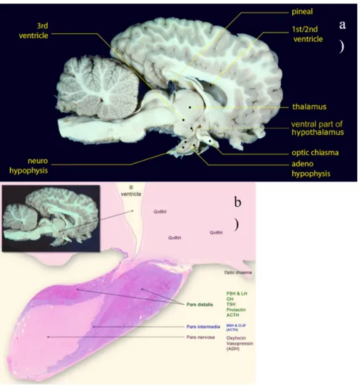
1.1 Location of the Horse Pituitary Gland. In a) we can see an image of a brain of a horse and the location of the pituitary gland. In b) we can see the different lobes: pars distalis, pars intermedia and pars nervosa (McFarlane,2013). . . 2
1.2 Horse Pituitary adenoma. (A) - Pituitary hyperplasia was confirmed histologically in this gland from a 25-year-old Welsh pony mare presented with all the signs of pituitary pars intermedia dysfunction (PPID/equine Cushing’s disease). (B) - A 13-year-old bay Thoroughbred mare was presented with a 3-week history of weight loss, inappetence and progressive central nervous signs including circling and left eye central blindness. MRI identified a well-defined (3×3×3cm) mass in the pituitary gland. At necropsy, this was confirmed as a pituitary macroadenoma. Notice also the small (possibly insignificant) cholesterol granuloma in the third ventricle (arrow) (Knottenbelt et al.,2015). . . 3
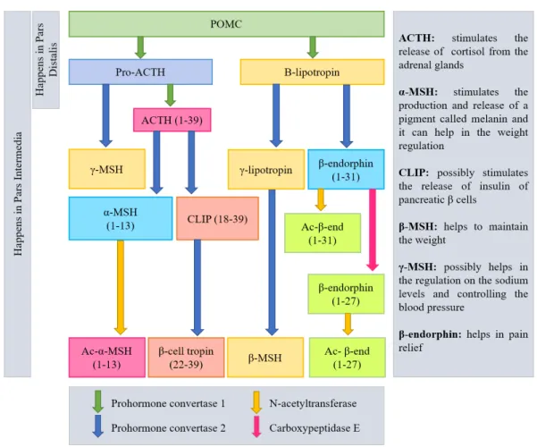
1.3 Pro-opiomelanocortin (POMC) processing pathway. POMC is processed differently in the corti-cotrophs of the pars distalis than in the melanotrophs of the pars intermedia. In the right side there is a resume of the functions of some hormones. Adapted from Knottenbelt et al.(2015);
National Institutes of Health(2016). . . 5
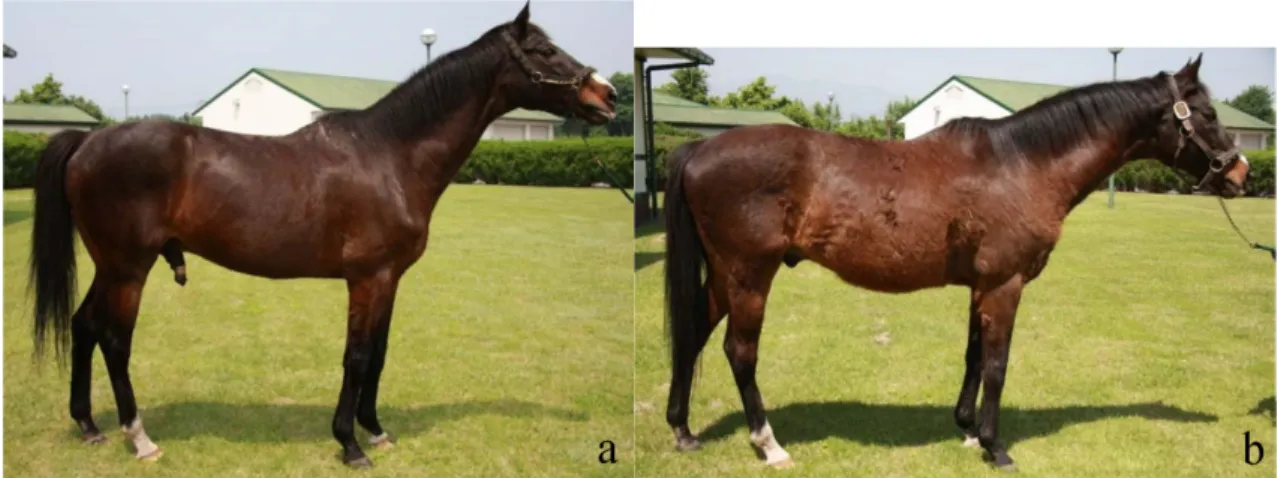
1.4 Horse with Hirsutism. Appearance of the stallion before (a) and after (b) getting the disease – picture (b) was take 1 year after the first one. (Hatazoe et al.,2014). . . 6
2.1 Three different ways of removing pituitary tumours in humans. Transcranial (left), transseptal-transsphenoidal (middle) and transnasal-transseptal-transsphenoidal (right) surgical routes (Arkenbout,2012). 7
2.2 Transnasal Approach. Left image: the surgeon uses and endoscope and other instruments to remove the tumour. Right image: a fat graft is placed in the area where the tumour was removed. A cartilage graft is placed to close the hole in the sella. Biologic glue is applied over the area (Arkenbout,2012).. . . 8
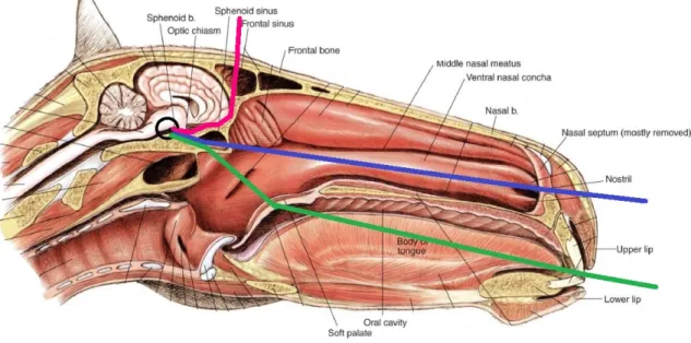
2.3 Median section of the horse’s head. Nasal septum mostly removed.The 3 lines represent the 3 different approaches used in humans: pink - transcranial; blue - transnasal; green - transseptal. The black circle represents the pituitary gland. Adapted fromMcCraken et al.(2015). . . 8
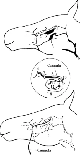
2.4 Cannula insertion procedure in the pituitary gland. The cannula within the deep facial vein enters the cranial cavity at the circled point, which is expanded in the centre of the Figure. The cannula insertion site is marked by the letter S on the bottom picture. 1. Facial vein; 2. deep facial vein; 3. sinus of the deep facial vein; 4. ophthalmic vein (orbital drainage); 5. transverse facial vein; 6. jugular vein; 7. entry of the deep facial vein into the cranial cavity (dotted line) at the foramen orbitorotundum; 8. cavernous sinus; 9. intercavernous sinus; 10. Connections to ventral petrosal sinus and large venous circuits; 11. pituitary gland: the site of entry of the paired pituitary veins into the intercavernous sinus is marked by arrows (Irvine & Alexander,
1987). . . 10
3.1 Representation of the biopsy harvester inspired by the Aristotle’s lantern and its working prin-ciple combining optical and mechanical biopsy (Jelínek et al.,2014). . . 13
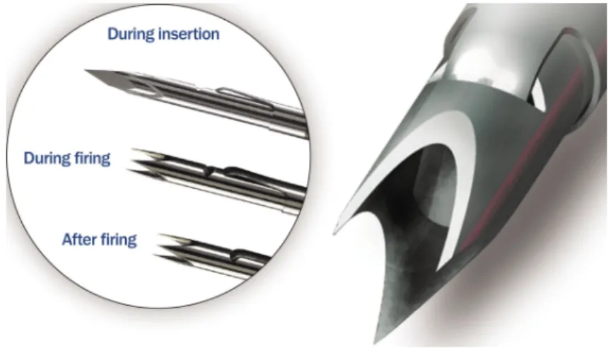
LIST OF FIGURES 3.2 Representation of the biopsy device called BioPince. On the left, we can see three imagens of
the device: during the insertion on the tissue and before firing - the first one, during the firing to harvest a sample - second one, and the last one shows the device after firing and harvesting the tissue sample. The image on the right shows a zoomed picture of BioPince’s distal end (ARGON MEDICAL,2017). . . 14
3.3 Scheme representing both ways of transportation the debris. On the left, we an see a grasper technique for contact initiation with the cutting edge (purple) and tissue (pink) transportation. On the right, an aspiration technique using pressure difference for contact initiation with the cutting edge (purple) and tissue (pink) transportation is showed. The blue arrows indicate the direction of the force on the tissue and tissue transportation direction (Sakes et al.,2013). . . . 15
3.4 The first instrument created for horses with the purpose of reaching and removing the tumour in the pituitary gland in horses using the vascular system. The image on the left represents the distal end of the device with a match for scaling and the image on the right is a scheme of the cutting part (Sakes et al.,2013). . . 16
4.1 Basic scheme of the pituitary gland’s surroundings. . . 18
4.2 Schematic representation of some of the requirements for the device. . . 19
4.3 Schematic representation of axial and radial force directions, with two possible motions: rotation and translation. Both force directions and motions can be used for two different purposes on a mechanical device, to actuate the device and to debulk tissue. . . 20
4.4 Illustration of the seven first designs discussed. On the left side we have three cutting parts with axial translation and rotation and, on the right side, four debulking parts with axial and radial translation. . . 21
4.5 The final three designs are represented. Cutting directions are illustrated as black arrows and different parts of the device have different colours: dark green - blades, light green - inside tubes, grey - inside pieces, blue - flexible shaft . . . 22
4.6 First prototype made in SolidWorks. The prototype revealed some problems, as the difficulty in the construction of the wire and stability problems. . . 23
4.7 The debulking component is composed of three parts: (A) the blade, (B) inside tube and (C) outside tube . . . 25
4.8 The debulking component is composed of three parts: (A) the blade, (B) inside tube and (C) outside tube. The dimensions are in millimetres (mm). . . 25
4.9 Scheme of the Maxon motor’s dimensions on the left and a picture of the real motor on the right. 26
4.10 Scheme of the Maxon motor’s dimensions . . . 26
5.1 Sketch of the blade component (A) with some measures. The picture on the left represents a view from the top and picture on the right from a side view. The measures are in mm. . . 28
5.2 The three components that compose the cutting part of the device were assembled . . . 29
5.3 All seven components were assembled to obtain the final prototype . . . 29
List of Tables
1.1 Measurements of the normal equine pituitary gland in 22 horses using Computed Tomography images. Study made byMcKlveen. . . 4
1.2 Measurements of the pituitary gland in 19 horses with clinical signs of PPID using Computed Tomography images. Study made byPease et al.. . . 4
4.1 Representation of the debulk force directions and the two ways to minimize tissue deformation. The four forces that could be used are: axial translation, axial rotation, radial translation and radial rotation. Is this table we made combinations of those forces with two ways of minimizing tissue deformation, keep forces internal or using the tissue’s inertia, to study the best way. *Adapted from (Sakes et al.,2015). . . 20
Chapter 1
INTRODUCTION
1.1
The Pituitary Gland
The pituitary gland or hypophysis is an endocrine gland situated in the brain and sometimes it’s described as the master gland, because it plays a key role in maintaining homeostasis and controls many functions of other glands in the endocrine system. This gland is an extended attachment of the brain lying within a bony cavity of the sphenoid bone in the base of the skull - the Sella Turcica. It is suspended ventral to the hypothalamus by a thin infundibular stalk (Dyce et al.,2010).
In vertebrates, the pituitary gland is divided into three different lobes: pars nervosa (neuro-hypophysis or posterior pituitary), pars intermedia (intermediate lobe), and pars distalis (adeno-hypophysis or anterior pituitary), each having a unique role in endocrine homeostasis. In horses and other equine species, the adenohypophysis surrounds the other pituitary lobes, as we can watch in Figure 1.1. This work will focus in the pars intermedia because is in this area that pituitary gland tumours appear with more frequency. The pars intermedia is composed by an homogenous cell population of melanotropes and it’s responsible for the synthesis and secretion of pro-opiomelanocortin (POMC) as well as the pars distalis. The POMC is converted in mul-tiple peptides, as you can see in Figure 1.3. This secretion is controlled by dopamine released directly from neurons from the hypothalamus.
Finding images or anatomic descriptions about the organs, veins and cavities that surrounds the pituitary gland in literature it’s really difficult. To understand better the environment and for the purpose of this project, it’s important to have in mind the structures and sensitive tissue located in that area. For that, after some research and talking with a veterinarian, Doctor Har Van Der Kolk from the University of Utrecht, a basic scheme design came up and can be observed in chapter 4, Figure4.1. This figure may be useful while designing the device and its actuation and debulking methods, but we will speak about this in a few chapters.
1.2
Cushing’s Disease
Cushing’s syndrome is a rare, chronic and systemic disease caused by hypercortisolism (endoge-nous or exoge(endoge-nous). Cushing disease is caused by endoge(endoge-nous hypercortisolism and it’s a serious condition of an excess of the steroid hormone cortisol in the blood level due to an increase se-cretion of adrenocorticotropic hormone (ACTH). ACTH is a hormone produced by the pituitary gland. This disease is normally caused by a tumour in the pituitary gland, next to the hypotha-lamus, which autonomously secrets cortisol and causes a disturbance in the cortisol feedback mechanism in the hypothalamic-pituitary-adrenal axis. ACTH stimulates the adrenal glands (located on top of the kidneys) to produce cortisol, commonly referred to as the stress hormone. Cortisol is a steroid hormone present in our body everyday and it has many important functions
1.2 Cushing’s Disease
Figure 1.1: Location of the Horse Pituitary Gland. In a) we can see an image of a brain of a horse and the location of the pituitary gland. In b) we can see the different lobes: pars distalis, pars intermedia and pars nervosa (McFarlane,2013).
including: maintaining normal blood pressure (inadequate cortisol production is usually associ-ated with low blood pressure), response to stress situations (an increased blood level of cortisol is essential for us to be able to cope with acutely stressful situations), increasing the body’s metabolism of glucose, controlling the blood pressure, reducing inflammation, among others. So, having the right cortisol balance is essential.
1.2.1 Equine Pars Intermedia Dysfunction
Cushing disease can affect humans and animals, like horses. Is one of the most common endocrine disease in elderly horses (18 – 23 years) and in Morgan horses and ponies (Knottenbelt et al., 2015). Over the years, the disease has had a few name changes, with “equine Cushing’s disease” the most commonly accepted name and "equine Pituitary Pars Intermedia Dysfunction” (PPID) the most currently accepted name in the veterinary community (Posnikoff, 2005). Horses with PPID, unlike humans, have almost exclusively adenomas in pars intermedia (intermediate lobe, see Figure 1.1) ) instead of in pars distalis or pars nervosa (McFarlane et al.,2006).
1.2.2 Tumour in the Pituitary Gland
The majority of the equine pituitary tumours appear in the pars intermedia of the pituitary gland and it usually affects 85% of horses with more than fifteen years of age (Knottenbelt et al. n.d.). Is still under debate if these tumours are benign neoplasms or if they are a consequence of
1.2 Cushing’s Disease the loss of dopaminergic inhibition of the pars intermedia. Recently, it was discovered that it’s more likely to be a neurogenerative disease instead of a primary neoplastic process. Dopamine can inhibit the activity in the pars intermedia and it’s released in this area by hypothalamic periventricular neurons. These neurons innervate the melanotrophs cells. This theory proposes that age-related oxidative stress degeneration in this neurons in horses with PPID allows a melan-otrope proliferation, which causes an excessive synthesis and processing of POMC (McFarlane, 2007).
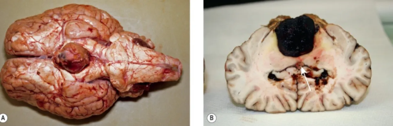
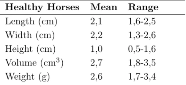
The pituitary gland in horses with PPID is usually increased, normally between 2-5 times the normal size. An example of that is described in Figure1.2. Benign tumours in the pituitary gland are called adenomas and they have their basis in epithelial tissue with glandular origin. The adenomas can be microadenomas or microadenomas, according to their size. Microadenomas normally have <0.5 cm of diameter and adenomas normally measure 1-3 cm. In a study made by Pease et al., twenty-two horses without PPID were analysed using Computer Tomography imaging and the sizes of pituitary glands in these horses can be observed in Table 1.1. The measured mean values for length, width, height and weight are 2.1 cm, 2.2 cm, 1.0 cm and 2.6 g for a normal pituitary gland, as opposite to 2.6 cm, 2.4 cm, 1.9 cm and 7.7 g as mean values for horses with PPID, as shown in Table1.2, where nineteen horses were analysed. Some values were not significantly great, as the length or width. However, in the rest of the values we can see a big difference. The biggest change in pituitary gland size between PPID-affected and normal horses was in pituitary gland height. After analysing and comparing the anatomy of the gland and the three measures, a likely explanation for the increase in the height is the limited location of the pituitary gland. This gland is situated within the hypophyseal fossa of the sphenoid bone. Although the pituitary gland is surrounded by fibrovascular tissue within the hypophyseal fossa, the incomplete diaphragm sellae, between the dorsal surface of the gland and the hypothalamus, offers a path with less resistance for the gland to expand.
Figure 1.2: Horse Pituitary adenoma. (A) - Pituitary hyperplasia was confirmed histologically in this gland from a 25-year-old Welsh pony mare presented with all the signs of pituitary pars intermedia dysfunction (PPID/equine Cushing’s disease). (B) - A 13-year-old bay Thoroughbred mare was presented with a 3-week history of weight loss, inappetence and progressive central nervous signs including circling and left eye central blindness. MRI identified a well-defined (3×3×3cm) mass in the pituitary gland. At necropsy, this was confirmed as a pituitary macroadenoma. Notice also the small (possibly insignificant) cholesterol granuloma in the third ventricle (arrow) (Knottenbelt et al.,2015).
1.2 Cushing’s Disease
Table 1.1: Measurements of the normal equine pituitary gland in 22 horses using Computed Tomography images. Study made byMcKlveen.
Healthy Horses Mean Range Length (cm) 2,1 1,6-2,5 Width (cm) 2,2 1,3-2,6 Height (cm) 1,0 0,5-1,6 Volume (cm3) 2,7 1,8-3,5
Weight (g) 2,6 1,7-3,4
Table 1.2: Measurements of the pituitary gland in 19 horses with clinical signs of PPID using Computed Tomography images. Study made byPease et al..
Horses with PPID Mean Maximum Length (cm) 2,60 ± 0,31 3,3
Width (cm) 2,42 ± 0,26 2,9 Height (cm) 1,92 ± 0,43 2,7 Weight (g) 7,70 ± 3,30 13,9 1.2.3 Pathophysiology
The current pathophysiological theory for PPID is an age-related oxidative stress-induced neu-rodegeneration of the dopaminergic neurons of the hypothalamus. This neuneu-rodegeneration causes a loss of dopaminergic inhibition on the pars intermedia resulting in an increased production of pro-opiomelanocortin (POMC)-derived peptides. Dopamine is a neurotransmitter released by the brain which plays several roles in humans and other animals, helping maintain blood sugar levels, protecting the body from stress and stopping (suppressing) inflammation. An excess or deficiency of this vital chemical is the cause of several disease conditions, as Parkinson’s disease in humans (Mandal,2015). The pars intermedia is regulated by the hypothalamus. The neurons of the hypothalamus innervate cells in the pars intermedia, melanotropes (or melanotrophs), re-leasing dopamine. This will activate the receptors of dopamine in the melanotropes cells, which will lead to the inhibition of POMC production in these cells. POMC is the pituitary precursor of some peptides hormones: adrenocorticotropin (ACTH), α-melanocyte-stimulating hormone (α-MSH), β-endorphin and corticotrophin-like intermediate peptide (see Figure 1.3). In horses with PPID, some neurons of the hypothalamus don’t produce dopamine, leading to a decrease in the dopamine levels. Without dopamine’s regulation, the pars intermedia is more prone to develop hyperplasia (increase in the amount of organic tissue due to cell proliferation) and ade-noma (benign tumor of epithelial tissue) formation. This causes excessive production of POMC and, as a consequence, as excessive production of ACTH. In a normal case, the pars distalis, which is controlled by a glucocorticoid negative feedback loop, is responsible for almost all the quantity of ACTH and just a little amount comes from the melanocyte-derived POMC. However, due to the loss of dopaminergic inhibition, POMC levels won’t be controlled.
1.2.4 Clinical Signs
The increase of the pituitary hormones can bring some clinical signs. The most well-known sign is the hirsutism which is, as you can see in Figure1.4, an excessive hair growth or abnormal retention of the hair coat in the summer. Cushing’s disease often compromises the immune system, causing horses with this condition to be more prone to infections and other health problems, such as
1.2 Cushing’s Disease
Figure 1.3: Pro-opiomelanocortin (POMC) processing pathway. POMC is processed differently in the corti-cotrophs of the pars distalis than in the melanotrophs of the pars intermedia. In the right side there is a resume of the functions of some hormones. Adapted fromKnottenbelt et al.(2015);National Institutes of Health(2016).
delayed healing or tooth abscesses, sinus infections and chronic fungal and bacterial or parasite infections. Pneumonia is even possible (Mcgowan et al., 2013). Cushing’s horses are generally lethargic, sweat easily, tend to run high temperatures, drink and urinate excessively and have fertility problems. An older horse with Cushing’s is truly a “special needs” horse. The most serious complication of PPDI is Laminitis, which is a painful and severe inflammation of the internal lamellar of the horse foot due to an alteration of the peripheric vascular flood flow. Horses with PPID may also be insulin resistant.
1.2.5 Treatment
The treatment in horses try to control and reduce the severity of the clinical signs using oral medication, because removing the pituitary gland by surgery, so far, has been technically im-possible. A few drugs have emerged for treating equine Cushing’s disease from three classes: either dopamine agonists (e.g. bromocriptine and pergolide), serotonin antagonists (e.g. cypro-heptadine), or a 3β-hydroxysteroid dehydrogenase inhibitor (trilostane), acting to block adrenal steroidogenesis. A studied showed that pergolide is more effective than cyproheptadine for treat-ing this disease (Spelta,2015), so, today, pergolide is the most commonly used drug. This drug, also used to treat Parkinson’s disease in humans, stimulates dopamine release. The replacement of dopamine and reestablishment of dopamine inhibition on the POMC-derived peptides results in the normalization of pituitary hormone levels and less clinical signs. The costs of this medica-tion depends on the weight of the horse, but for a large horse it can cost five to ten euros a day. The prognosis of equine Cushing’s disease is highly dependent on the effect of the medication, the observed clinical signs, the progression of the disease, and the willingness of the owner to
1.3 Goal of the Project
Figure 1.4: Horse with Hirsutism. Appearance of the stallion before (a) and after (b) getting the disease – picture (b) was take 1 year after the first one. (Hatazoe et al.,2014).
properly manage the horse. So, the necessity of discover a new treatment that could provide a more effective way is getting higher as the population of elderly horses increase and, therefore, also the population with Cushing’s disease.
1.3
Goal of the Project
In humans, the therapy of choice is the surgical removal of the adenoma. There are three different ways to access the pituitary gland and to remove it: the transnasal transsphenoidal, transseptal transsphenoidal, and transcranial approach. However, those methods are difficult to use in horses because it would be necessary to drill through several centimetres of bone and to use extremely long and slender instruments that are currently non-existent. Until today, as no surgical treatment of the equine pituitary gland has been attempted, the post-surgical results are still unclear (Sakes et al.,2015).
So, the objective is to create a way that enables an instrument to arrive at the pituitary gland in horses. It has been developed a new way to get access to this gland: the intercavernous sinus of the pituitary outflow tract can be accessed via a venous pathway unique to equids. It can be accessed by the superficial facial vein midway between the anterior end of the facial crest and the ventral border of the mandible. This superficial vein can be used to guide a flexible instrument towards the pituitary gland.
The main goal of this project is to design and prototype an instrument capable of reach and remove the pituitary gland in horses, and to discuss the feasibility of this approach. The focus will be the debulking part of the instrument. It has been determined that mechanical morcellation is a potentially method for the surgical treatment of Cushing’s disease in horses. A morcellator is a surgical instrument used for division and removal of large masses of tissues during laparoscopic surgery (minimally invasive surgery). It’s is a steerable device, which means that it is capable of being managed or controlled. Some literature review is showed in the next chapters.
Chapter 2
ROUTES TO THE PITUITARY
GLAND
2.1
Surgery in Humans
In humans with a pituitary tumour there are three different ways to access the pituitary gland and to remove it: the transnasal transsphenoidal, transseptal transsphenoidal, and transcranial approach. The surgeon chooses the route depending on the size and shape of the tumour. In Figure 2.1those routes are represented.
Figure 2.1: Three different ways of removing pituitary tumours in humans. Transcranial (left), transseptal-transsphenoidal (middle) and transnasal-transseptal-transsphenoidal (right) surgical routes (Arkenbout,2012).
The transsphenoidal approach uses the nasal cavity to access the pituitary gland through creating bone holes in the sphenoid sinus and in the sella (transsphenoidal). The nasal cavity can be reached through the nose (transnasal) or by an incision under the upper lip (transseptal). The thin bone of the sella is removed to expose the hard piece of the skull called the dura. The dura is opened to expose the tumor and pituitary gland. Through a small hole in the sella, the tumor is removed in pieces by the neurosurgeon with special instruments called curettes. This procedure can be done with a surgical microscope or fully endoscopically. After the tumor is removed, the surgeon prepares to close the sella opening. If needed, a small (2cm) skin incision is made in the abdomen to obtain a small piece of fat. The fat graft is used to fill the empty space left by the tumor removal. The abdominal incision is closed with sutures. The hole in the sella is replaced with bone graft from the septum or synthetic graft material (for example when there is no suitable piece of septum). In the sphenoid sinus is applied biologic glue over the graph to allow a better healing and to provent leak of cerebrospinal fluid (CSF) from the brain. This approach can be observed in Figure 2.2.
In the transcranial approach, a bone flap is temporarily removed from the skull to access the brain. The brain is pushed up and backwards to give access to the pituitary gland. This
2.2 Surgery in Horses
Figure 2.2: Transnasal Approach. Left image: the surgeon uses and endoscope and other instruments to remove the tumour. Right image: a fat graft is placed in the area where the tumour was removed. A cartilage graft is placed to close the hole in the sella. Biologic glue is applied over the area (Arkenbout,2012).
procedure allows direct visual access to the tumour (Arkenbout,2012).
2.2
Surgery in Horses
2.2.1 Nasal/Palate Approach
The surgeries in humans are mostly done using the transnasal and transseptal methods. Trying these methods in horses is a possibility, however the head of the horse is bigger than a human head and nowadays there are no instruments that long. We would also need some bone-biting instruments to go through several centimetres of bone and some long instruments to achieve the pituitary gland. A representation of these approaches in an horse can be seen in Figure 2.3, where the pink line represents the transcranial approach, the blue line represents the transnasal approach and the green line represents the transeptal approach.
Figure 2.3: Median section of the horse’s head. Nasal septum mostly removed.The 3 lines represent the 3 different approaches used in humans: pink - transcranial; blue - transnasal; green - transseptal. The black circle represents the pituitary gland. Adapted fromMcCraken et al.(2015).
2.2 Surgery in Horses 2.2.2 Endovascular Approach
There is a unique path in equines that allows to achieve the pituitary gland using some veins and entering the body through the facial vein (see Figure 2.4). This approach was implemented for the first time by Irvine & Alexander to study the hormones in the pituitary gland using a cannula. This method is a good solution to achieve this gland because is less invasive than the others described before and the recovery should be faster. In their study, the cannula went in the body through the facial vein and it was manipulated into the deep facial vein, passing through the vena reflexa and going into the ophthalmic vein. After, they had to do a little curve for the cannula to pass through the ophthalmic vein and arrive in the cavernous sinus until it reached the end. The cannula was manipulated to go to the intercavernous sinus where there is a connection to the ventral petrosal sinus and large venous circuits, right next to the pituitary gland. Sakes et al. tried to use this unique path to achieve the pituitary gland with a morcellator and they succeeded. There are some aspects to considered, like the volume and direction of the blood, in particular past the intercavernous, because they might be affected by sporadic events such as changes in head position, chewing or a vascular reaction to the instrument itself (Irvine & Alexander,1987).
There were a few problems related to this approach in the study referred before. The most common one was the inability to pass the cannula into the ventral branch of the ophthalmic vein, where it should narrow to enter a small space, orbital foramen, and the cavernous sinus. Another problem was the difficulty to bend 90 degrees the cannula from the facial vein into the deep facial vein.
2.2.3 Advantages and Disadvantages
The nasal/palate approach is more invasive when compared to the endovascular approach and it’s necessary to drill several centimetres of bone to achieve the pituitary gland, which can be translated into a longer recovery time. Currently there are no instruments that can be used to do this procedure. The endovascular approach is less invasive and there is a path that can be used to achieve the gland. As the blood vessels are bigger in horses than in humans, it’s easier to do an instrument that can fit in the horses blood vessels. However, there are some complications that can happen, like damage in the blood vessel during the procedure or difficulty in finding the right path without a real time imaging. Additionally, in both procedures, a full anaesthesia will be needed.
2.2.4 Chosen Route
When we talk about choosing the best option, a particular subject that always has influence is the price of the treatment, in this case, the price of the medication and the surgery. If the price of the medication is lower than the device and the surgery, it will be difficult to insert this product in the market. That’s why this matter was brought into discussion with an expert veterinarian, Doctor Har Van Der Kolk, from the University of Utrecht. The expected cost for the medication can be different depending on the horse’s weight. For a large horse, the cost can be from 5 euros to 10 euros per day and the horse can live up from 5 to 10 years after the discover of the tumour, which means that the owner will pay a minimum of 9125 euros (5 euros per day, 5 years). To be sure that the horse has a tumour in the pituitary gland, normally the veterinarian asks for a computer tomography image of the brain, which will cost approximately 700 to 800 euros. On the other hand, Dr. Har Van Der Kolk thinks that the surgery, anaesthesia plus the surgery room and the work of the surgeon with a simple device, will cost around 350 euros, because it’s a non complicated procedure. In conclusion, the image of the brain and the medication during 5 years can have a minimum cost of 9825 euros, while the surgery, full anaesthesia and one image of the brain, should cost around 1050 to 1150 euros, with a simple device. This means that the
2.2 Surgery in Horses
Figure 2.4: Cannula insertion procedure in the pituitary gland. The cannula within the deep facial vein enters the cranial cavity at the circled point, which is expanded in the centre of the Figure. The cannula insertion site is marked by the letter S on the bottom picture. 1. Facial vein; 2. deep facial vein; 3. sinus of the deep facial vein; 4. ophthalmic vein (orbital drainage); 5. transverse facial vein; 6. jugular vein; 7. entry of the deep facial vein into the cranial cavity (dotted line) at the foramen orbitorotundum; 8. cavernous sinus; 9. intercavernous sinus; 10. Connections to ventral petrosal sinus and large venous circuits; 11. pituitary gland: the site of entry of the paired pituitary veins into the intercavernous sinus is marked by arrows (Irvine & Alexander,1987).
surgery not only can remove the tumour and not just the clinical signs, but it’s more than 8 times less expensive than the medication. So, surgery may be a good approach for this problem. Considering both surgery methods explain above and all their advantages and disadvantages, the chosen method was the endovascular way and the instrument will be design to fit and navigate through horses cavities and veins.
Chapter 3
STATE OF THE ART
In many surgical procedures, it is often necessary to remove tissue or diseased organs. This is especially challenging during small surgeries because the tissue or organ to be removed must be achieved through the small openings through which the procedure is performed. In these situations, it may be desirable to fragment (morcellate) or cut into smaller segments the bodily tissue so that it can be readily removed. This project is one of those cases, as the goal is to remove the pituitary tumour by endovascular access. This state of the art will focus in morcellators, their structures and techniques, and also in others instruments which may help in the design of the device.
3.1
Minimally Invasive Surgery
Minimally invasive surgery (MIS), also called Laparoscopic surgery, is a surgery performed with long thin instruments through small incisions and has been used for more than 25 years. In MIS, small skin incisions can be made with 0.5 and 1.5 cm of dimension, instead of one larger incision as in an open surgery, to achieve/remove the tissue. The main reason for this fast development in MIS are the benefits for the patient, human or animal, such as less trauma, lower infection risk by at least 35%, shorter hospital stay, and reduced recovery time (Pasam et al.,2015). However, this type of surgery also brings some difficulties for the surgeon, as errors or complications during the operation (Westebring – van der Putten et al.,2008). The biggest problem is the inability to remove large tissue masses through small incisions. A normal word used in the medical field is debulking, which means the surgical remove of as much of a tumour as possible. Currently, there are a few instruments that can be used in those kind of procedures and can cut tumour tissue in pieces, called morcellators.
3.2
Debulking
3.2.1 Morcellators
Morcellators are instruments normally used in less invasive procedures and mostly in abdomen and gynaecological surgeries (Advancing et al.,2014). There are three major types of morcella-tors, regarding their debulking technique: mechanical morcellamorcella-tors, non mechanical morcellators and hybrid morcellators. The first described manual morcellator was created by Semm in 1973 and it was developed to facilitate large tissue mass removal during laparoscopic surgery (Semm, 1978). Since then, various morcellators have been designed and brought to the market. With the introduction of the electromechanical morcellator, the morcellation rate rapidly increased (Sakes et al.,2013).
3.2 Debulking Mechanical morcellators generally consist of a hollow slender shaft with a specialized de-bulking structure (normally with a blade) on the distal end, which enables the instrument to resect the tissue. As the mechanical morcellators were the first to appear, there are a lot more research and patented/non patented instruments in the market. They are normally easier to use and they require less training by the doctors. However, the inability to coagulate small blood vessels during the surgery is dangerous, it can result in excessive blood loss and reduced vision. In non-mechanical debulking, high temperatures such as used in electrosurgery, electrocautery, and lasers, or high-frequency vibration, such as used in ultrasonic dissection, are used to debulk the tissue. They are able to support more functions - tissue selection, coagulation, vaporization, sublimation and debulking - which makes them more versatile. However, they may experience some problems like the difficulty to control, accumulation of heat, higher cost, higher need for training, complexity of the device and consequence complexity of the manufacture process. Some hybrid techniques appeared with de advantage of being optimized for a specific application and targeted tissue type, which may result in higher efficiency of the debulking process. The bad news for this new hybrid techniques are, of course, the increased complexity of the instrument, due to the use of two cutting techniques, which results in an increased cost and it could decrease the ergonomics of the instrument. Also, surgeons may need more training and it may be more difficult to control than a mechanical morcellation instrument.
In this paper, the focus will be on mechanical morcellators as they are the simplest and easier to manufacture than non mechanicals or hybrid ones. Also, the goal is to have a device that will be well accepted by the veterinarians so it shouldn’t be complex to manipulate neither it should need a great amount of training.
3.2.2 Debulking Structure and Forces
A morcellator can be divided into two different debulking categories: single-sided or double-sided structure. They differ in the result of forces when cutting the tissue. A morcellator with a single-sided structure only apply one action force on the tissue and the reaction force will be delivered by the environment. On the other hand, a double-sided device applies an action and a reaction force on the the tissue, creating a local force concentration. As the debulking is made, a single-sided cut will exert more force on the surrounding tissue and over a large area than a double-sided cut, where the instrument creates an action and reaction force in opposite directions. Thereby, this last one will concentrate the forces in a smaller area of the surrounding tissue, decreasing the side effects. There are some ways to reduce the force in the surrounding tissue when using a single-sided device, as creating a direct or indirect compensation just as described by (Jelínek et al.,2014). However, this compensation could increase the complexity of the debulking and the instrument itself.
The debulking process can be done using three force directions: axial, radial and tangential. An axial force is made when the tissue is cut longitudinally to the axis of the morcellator. A radial force is created cutting the tissue along the radial/lateral axis of the morcellator and the tangential force follows the tangent of the instruments shaft. A device can be made to allow cuts in more than one direction. The right geometry and debulking structure/technique should be choose for the device’s purpose, because different forces can bring different advantages or problems. For example, when a tangential force is applied, the tissue will spread in many directions and it can be difficult to control where the debris go. Will axial or radial force, it may be easier to make a clean cut.
3.2.3 Debulking Methods
The general features of a morcellator device are the blade diameter, cutting speed (revolutions per time scale), weight and working principle. The resection part of the instrument part can be frontal or in the lateral side, depending on the target. The type of grip and grasper used in the
3.2 Debulking morcellation process can affect the procedure time and a strong and secure grip of the tissue is required for a stable and adequate cut. So, the type and number of jaws in the grasper should be adapted to the consistency of the target tissue. It should be rigid to facilitate the cut and to give stability and, the shorter the resection part is, more flexible the instrument will be.
There are four types of debulking tissue through mechanical morcellation, called the working principles: coring, peeling, nibbling and shaving. In the coring principle, the target tissue is pulled towards a cylindrical blade, hollow in the inside. Motor peeling is the successor of the motor coring principle and currently is the fastest working principle. This technique, very similar to the coring one, uses an overhanging edge at the distal end of the morcellator, which facilitates the contact between the blade and the tissue. Continuous tissue removal it’s easier with this method and it also offers the highest morcellation rate, because the tissue pieces removed using this method can be bigger/longer than with the motor coring principle (Driessen et al.,2014). Compared with the coring principle, the peeling principle is potentially a safer approach because direct vision during the morcellating process is constant when using an imaging technique. The nibbling method consists in debulking tissue with a blade that slides continuously from the top to the distal side of the instrument (axial translation), nibbling small pieces of tissue on the lateral side. Finally, the shaving method uses an axial rotating blade that shaves tissue on its way (Sakes et al.,2013).
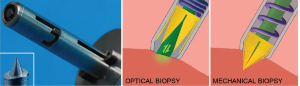
Although morcellators are the ones used for debulking, in this section we are going to focus not only in morcellators, but also in biopsy devices as they are able to cut through tissue as well in minimal invasive procedures (Jelínek et al., 2014). Biopsy is a medical test used to remove a tissue sample to study its nature and properties in a laboratory. The most common biopsy techniques are: fine needle aspiration, core needle biopsy and punch biopsy, being the last one the most invasive. There are a huge variety of biopsy instruments with different formats, depending on its purpose. A bioptome is a catheter-based biopsy system used to make extractions of tissue from within the body. There are two basic types of bioptomes: stiff devices that are manoeuvred independently through the vasculature and more flexible devices, that can be positioned only with the aid of a long sheath or introducing catheter. These bioptomes are widely used in cardiac biopsies (Baim,2000;Werner P. Schulz,1975). BioPince is a full core biopsy instrument that uses a tri-axial core, cut and capture system to harvest a tissue sample while reducing the risk of crush artifact and tissue fragmentation. A full cylindrical sample is harvested for clinical diagnosis and we can see the different phases of inserting and firing to capture the tissue sample in Figure 3.2 (Sundheimer & Ireland,2010). Jelínek et al. designed a disposable laparoscopic (abdominal invasive surgery) instrument tip inspired by the sea urchin’s chewing organ, Aristotle’s lantern, and its capability of rapid and simultaneous tissue incision and enclosure by axial translation. This biopsy device, shown in Figure 3.1, was designed to cut the tissue fast and accurately and it incorporates a glass fibre for tissue diagnostics and a container to storage the tissue sample.
Figure 3.1: Representation of the biopsy harvester inspired by the Aristotle’s lantern and its working principle combining optical and mechanical biopsy (Jelínek et al.,2014).
3.3 Shaft and Actuation
Figure 3.2: Representation of the biopsy device called BioPince. On the left, we can see three imagens of the device: during the insertion on the tissue and before firing - the first one, during the firing to harvest a sample - second one, and the last one shows the device after firing and harvesting the tissue sample. The image on the right shows a zoomed picture of BioPince’s distal end (ARGON MEDICAL,2017).
3.3
Shaft and Actuation
For this project, the morcellator body has to be flexible as the surgery will be performed in a sensitive and non linear path: the veins and cavities. For that, we will need flexible shafts. A flexible shaft transmits rotary motion much like a solid steel shaft, but it can be routed over, under, and around obstacles that would make using a solid shaft impractical. Unfortunately, all morcellators found in literature are not flexible, except for the one created bySakes et al. with the same purpose.
One traditional type of flexible instrument used commonly in the medical field is the catheter. A catheter is a thin and flexible tube that can be used in a lot of surgical procedures, as a drug delivery system or to perform a surgical procedure, for example. A steerable catheter is a catheter capable of being managed or controlled. This instrument is among the most used in cardiology in humans because it was proved to reduce the procedure time and increase the patient safety (Ali et al.,2016). Catheters may be provided in a variety of different shapes and sizes depending on the application. It is typical for a surgeon to manipulate the proximal end of the catheter to guide the distal end of the catheter inside the body, for example, through a vein or artery (Weitzner & Murphy,2002). There are three most common catheter materials: vinyl catheters, red rubber latex catheters and silicone catheters. Vinyl catheters, also known as PVC (Polyvinyl chloride), are one of the most popular. Red rubber latex catheters are not suitable for those with latex allergies or sensitivities. Silicone is one of the top materials of choice for many doctors, due to the material being highly tested and widely used over time. It’s also antibacterial, good for people with allergies and its flexibility fits between vinyl and rubber latex. To find the perfect choice of material it’s difficult, it depends on the anatomy and the surgery needs (Jessica,2014). The flexible shaft and the remaining components will have tu be actuated though blood vessels and cavities and the tumour to remove it. Actuation on these devices can be done by the same way as debulking: three different force directions - axial, radial and tangential - and two different motions - rotational and translational.
3.4
Transportation
All types of morcellation instruments engage and transport the tissue using one of two approaches: a manual approach using a small minimal invasive grasper, or an aspiration method. In the grasper approach, the traction force (used for contact initiation) is created by grasping the tissue with the minimal invasive grasper and, subsequently, moving it towards the distal cutting edge
3.5 Complications of the morcellator, as is illustrated in Figure 3.3. Continuation of the retraction motion of the minimal invasive grasper towards the proximal end of the morcellator will transport the tissue away from the operation area. In the aspiration approach, the pressure difference between the distal and proximal end of the morcellator is used to create the needed traction force to bring the tissue into contact with the cutting edge and, subsequent, transportation. For safety reasons, the tissue is always pulled towards the distal cutting edge of the morcellator, rather than moving the morcellator towards the tissue.
Figure 3.3: Scheme representing both ways of transportation the debris. On the left, we an see a grasper technique for contact initiation with the cutting edge (purple) and tissue (pink) transportation. On the right, an aspiration technique using pressure difference for contact initiation with the cutting edge (purple) and tissue (pink) transportation is showed. The blue arrows indicate the direction of the force on the tissue and tissue transportation direction (Sakes et al.,2013).
3.5
Complications
There can be some complications inserting the device in the blood vessels or during the cut or transportation of the tumour tissue. One of the principal concerns with the use of morcellators during abdomen or pelvis surgeries is the dissemination of small pieces of uterine or fibroid tissue, sprayed by the centrifugal force of the spinning blades or during the withdraw of the device. These bits of tissue can adhere to other organs and tissues, starting new tumours (Advancing et al., 2014). As well as in these surgeries, the same problem can occur during surgeries with this device in horses. In an interview with a veterinarian from the University of Utrecht, we talked about this issue. We concluded that this is something that could happen and should be solved in the future. The blood loss and coagulation is also a problem and to solve that the transportation method should have this in consideration and the cutting should be as fast as possible. During the debulking of the tumour, it’s also important to prevent damage in the surrounding healthy tissue, as well as inserting the device, to not to damage the blood vessels neither cavities.
3.6
Endovascular Morcellator
Sakes et al. tried to design, prototype and test an instrument capable of reach and remove the tumour in the pituitary gland using the vascular system, also testing the feasibility of this approach. It was the first instrument created for horses with this purpose and its illustrated in Figure 3.4.
To understand more about the geometry of the device, there was a need to know more about the horse and its measures. Unfortunately, it’s difficult to find any information about those dimensions in the literature. Therefore, they had to measure them using three cadaver heads
3.7 Forces applied on the device from adult Dutch Warmblood horses, drained out of blood. The drained lumens of the facial veins had an average of 6 mm in diameter. Due to the fact the measure was made without blood and the diameter of the veins decrease as we get to the pituitary gland, a maximum of 5 mm in diameter was set for the device. Concerning the length, they inserted a catheter from the facil vein and an average of 300 mm was registered. To compensate for anatomical variations, they set 350 mm as the minimum length required. As last, using an x-ray image of the sagittal plane of the horse’s head, the bending radius was measured. The minimum bending radius that the instrument needs to accommodate on route to the pituitary gland was set as 21 mm. After analysing these dimensions, and with the goal in mind, they discovered that the maximum rigid tip length at the distal end of the morcellator should be about 14 mm.
The instrument came up as a single flexible morcellator with a cutting forces internally balanced and a rotational cutting blade. The debulking is continuous and debulked tissue is removed from the operation site by aspiration. The authors concluded that this method for treatment of Cushing’s disease in horses is feasible. Unfortunately, there were some problems with the instrument. The transportation method, aspiration, proved to be insufficient to transport the tissue towards the container. The instrument was big and it didn’t cut continuously the tissue. For that problem, the blade should be redesigned. Clinical applications need more research and the morcellator should continue to be optimized and expanded upon for clinical use.
Figure 3.4: The first instrument created for horses with the purpose of reaching and removing the tumour in the pituitary gland in horses using the vascular system. The image on the left represents the distal end of the device with a match for scaling and the image on the right is a scheme of the cutting part (Sakes et al.,2013).
3.7
Forces applied on the device
Blood is a two-phase fluid, a fluid which has two fluids with different viscosities, because first it’s composed by plasma and second by blood cells. There will be some hydrostatic forces that the blood transmits onto the device. If the object is moving through the blood, the hydrostatic forces will change, so it’s important to qualified and quantified them, as well as the total force acting in the device (Rubenstein et al.,2015). For the purpose of this study, those forces aren’t taking into consideration.However, in future studies, they should be considered and analysed.
3.8
Redesign
After analysing the actual morcellators and biopsy instruments in the market, there is a need to redesign or complete redevelopment to utilize a morcellator in the flexible endovascular approach for the surgical treatment of Cushing’s disease in horses. In the next Chapter, the design process of the a new flexible morcellator will be discussed, with focus on the debulking technique and its components.
Chapter 4
DESIGN
4.1
Requirements
When thinking about designing a new device, a proper research about the different methods and technologies that exist in the market is an important step and it allows us to see what can and what can’t be done. However, there is a crucial matter we should to take in consideration: the environment where the surgery will be performed. The difficulty to find a good image or description of that environment in literature was high, so, after some research and talking with Doctor Har Van Der Kolk from the Veterinarian University of Utrecht, a basic scheme design was sketched and it can be observed in Figure4.1. In this illustration, we can see how sensitive is the area and how big is the damage we could cause. During the debulking, the pituitary gland can’t move more than a few millimetres due to consequential damage in the veins or the optic nerve. For the purpose of this study, we will only focus our attention in the requirements of the environment and the device itself. Important aspects as the blood, its forces in the device and the spread of the debris aren’t taking into consideration. Nevertheless, in future studies, they should be considered and analysed. The goal is to have a simple device, easy to manufacture and easy to train and manipulate by the veterinarian surgeons. For that, our focus are the mechanical morcellators.
The path to the pituitary gland starts at the facial vein and goes on until the gland. This is an extensive and sinuous way to go, which will require a long and flexible instrument, as a catheter, which is a good option to be used for the shaft. The maximum external diameter of the device should be 5 mm to fit in all the veins and cavities and the minimum length was set as 350 mm. The shaft or catheter must have a minimum bending radius of 21 mm. For the device to be stable while cutting through the tissue, and to minimize the damage on the environment, the cutting part should be rigid. Because of that and to allow a good flexibility, that part has to be as minimal as possible and no more than 14 mm from tip to end.
4.1 Requirements
Figure 4.1: Basic scheme of the pituitary gland’s surroundings.
The pituitary gland is surrounded by big and important arteries, the optic nerve and sensitive tissue. The damage in the horse can be critical if the instrument slips of the way or debulk healthy tissue from another organ or even the arteries. We could have an internal haemorrhage and the horse could never recover from that. So, in order to prevent damage, the forces of action and reaction during the debulking process should be concentrated in the device or as much as possible . This means the instrument should have a double-sided debulking method, this way the pair action and reaction forces with be focus in the cutting part. If the total force is not zero, there is an option as we can try to compensate the force made by the device on the tissue, as (Jelínek et al.,2014) explained in his paper, and use the inertia of the tissue as a counterforce to prevent damage. Moreover, the tissue removing per cycle should be as large as we can to minimize the blood loss. As the anatomic shape of the tumour don’t have an arbitrary form, we may have to debulk from a rough tumour or a smooth/flat tumour. Also, we want it to be easier to achieve every corner inside the sella turcica and to minimize tumour cells left behind. For that, one of the requirements is for the instrument to be able to debulk on the frotn and to make a total cut. As for last, the cutting should be continuous to minimize the cutting time and the blood loss.
As a way to improve the device, a steerable component will help achieve almost all our requirements, but it will turn it more complex. The anatomical site is a very complex and sensitive place and to navigate with the instrument without being able to see the environment is a big risk that can cause real damage. An imaging technique incorporated in the instrument would be a great help to prevent go into the wrong cavities and blood vessels, to distinguish the tumour cells from the healthy cells and to prevent leave tumour cells behind. However, we should be careful choosing the right technique because it can increase the diameter of the device and turn it more expensive and complex to manufacture and manipulate. If that is not possible, an alternative could be set using an outside imaging technique to better see the instrument, as computed tomography, for example.
Mechanical morcellators are composed of a cutting part on the front and a shaft. The debris has to be transported from the surgical site to the outside of the body. The aspiration method can be dangerous because the tumour debris need to be pulled into the device and the quantity of blood aspirated can be critical. In this project we will try to design a device which uses a different technique to transport the remainings. Our main goal will be to focus our efforts on creating a good cutting blade which fulfil all the requirements.
Even with everything we discussed, it has to be as simple as possible: the same instru-ment should allow to visualize the area, navigate, cut the tissue and transport the debris. A representation of some of those requirements can be observed in Figure 4.2.