Abstract— We provide a brief overview of our recent studies concerning the effects of various mechanisms of plastic deformation of nanocrystalline materials on their fracture toughness. We consider both conventional deformation mechanisms, such as lattice dislocation slip, and the deformation mechanism pronounced mostly in nanocrystalline solids, such as grain boundary (GB) sliding and migration. It is demonstrated that with a decrease in grain size, the effect of conventional lattice dislocation slip on fracture toughness enhancement significantly decreases. At the same time, for nanocrystalline solids with finest grain size fracture toughness can be increased due to GB sliding and migration. This implies that a transition from lattice-dislocation-mediated toughening to GB-deformation-produced toughening can occur at a critical grain size in nanocrystalline solids.
Index Terms— nanocrystalline solids, fracture, plasticity, grain boundaries
I. INTRODUCTION
It is well known that nanocrystalline materials have superior strength and hardness that significantly exceed the corresponding characteristics of polycrystalline materials (e.g., [1–6]). The excellent mechanical properties of nanocrystalline solids are associated with the peculiarities of their structure, including the presence of high-density ensembles of grain boundaries (GBs) and nanoscale grains. In particular, interphase boundaries play the role of effective barriers for the motion of lattice dislocations, which represent the main carriers of plastic flow in grains, and thereby result in very high values of strength and hardness of nanomaterials.
At the same time, as the grain size of nanocrystalline materials decreases, many such materials become brittle. It is assumed that the brittle behavior of nanocrystalline solids is related to the presence of high-density ensembles of GBs that play the role of barriers for lattice dislocations. Indeed, in ductile polycrystalline materials crack growth is suppressed by means of lattice dislocation emission from crack tips. However, in nanocrystalline materials GBs limit dislocation emission from crack tips, which may lead to a brittle behavior of nanocrystalline materials. In this
Manuscript received February 11, 2012. The work was supported by the Russian Ministry of Science and Education (Contract 14.740.11.0353 and grant MD-164.2012.1) and the Russian Academy of Sciences Program “Fundamental studies in nanotechnologies and nanomaterials”.
Ilya A. Ovid’ko is with the Institute of Problems of Mechanical Engineering, Russian Academy of Sciences, St. Petersburg 199178, Russia (email: [email protected]).
Alexander G. Sheinerman is with the Institute of Problems of Mechanical Engineering, Russian Academy of Sciences, St. Petersburg 199178, Russia (email: [email protected]).
connection, along with dislocation plasticity, the alternative mechanisms of plastic deformation (that are essential precisely in nanocrystalline materials) acquire special importance. Such mechanisms include GB sliding, GB migration and rotational deformation, and the action of such mechanism can lead to an increase of the fracture toughness of nanocrystalline materials. The aim of the present work is to elaborate the models that describe the effects of grain size and plastic deformation processes on the fracture toughness of nanocrystalline materials.
II. EFFECT OF LATTICE DISLOCATION EMISSION ON FRACTURE TOUGHNESS IN NANOCRYSTALLINE SOLIDS Consider first the traditional mechanism of plastic deformation – the motion of lattice dislocations. We assume that in nanocrystalline materials cracks can be retarded as a result of dislocation emission from their tips. Also, when considering dislocation emission from crack tips, we assume that GBs can serve as stoppers for dislocations. In this case, the dislocations emitted from the crack tips will be stopped at the neighboring GBs, hindering the emission of subsequent dislocation from these tips. As a result, crack blunting in nanocrystalline materials may be less pronounced than in their polycrystalline counterparts. If crack blunting in nanocrystalline materials is insignificant, it does not prevent crack growth, and so nanocrystalline materials become brittle.
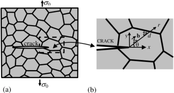
Fig. 1. Crack in a deformed nanocrystalline or ultrafine-grained solid. (a) General view. (b) The magnified inset highlights generation of edge dislocations near the tip of a long crack.
Note that the above scenario is realized in the situation where slip of lattice (perfect or partial) dislocations dominates in nanocrystalline materials. In particular, it is the case of room temperature deformation of nanocrystalline and ultrafine-grained metals having grain size d larger than the critical size dc
20 nm [6–9]. In these materials, one expects that emission of lattice dislocations from crack tipsMechanisms of Fracture Toughness
Enhancement in Nanocrystalline Solids
Ilya A. Ovid’ko and Alexander G. Sheinerman
(a) (b)
crack
0 0
d
CRACK
x y
b
is the dominant micromechanism for crack blunting at room temperature.
Let us calculate the critical parameters of dislocation emission from a tip of a blunt crack. To do so, consider a nanocrystalline solid under a remote one-axis tensile load (Fig. 1) The solid is supposed to be elastically isotropic and have the shear modulus G and Poisson ratio . Let a long flat crack grow in the solid, as it is schematically shown in Fig. 1. Following the approach [10,11], we model the crack as an elongated ellipse with a curvature radius at the crack tip, which is much smaller than the crack half-length a (Fig. 2). (The crack tip curvature radius is related to the ellipse semi-axes a and p as: 2
/ p a
.) We also introduce a Cartesian coordinate system (x, y) with the origin at the ellipse center and a polar coordinate system (r, ) with the origin at the right edge of the ellipse. In the Cartesian coordinate system, the stress yy created by the external
tensile load at the tip of the elliptic crack is in the following relationship with the crack tip curvature radius [10,12]:
2
( , 0) I
yy
K
x a y
, (1)
where KI is the generalized stress intensity factor [13]
assuming that the ellipse is replaced by a sharp crack. Following [10], we also suppose that the growth of the blunt crack occurs if the tensile stress yy at the crack tip
reaches some critical value p (yyp). Within the
macroscopic description (that does not consider details of the process at the crack tip), the crack grows if KI KIC. Combining this with the relation yy(xa y, 0)p and
formula (1), we obtain:
2 p IC
K . (2) Formula (2) is valid, when is larger than some critical radius c at which the crack tip can be considered as
curved. In the case of c (sharp crack), we use the
formula [14] br
4 / (1 )
IC IC
K K G , where is the specific surface energy.
Now consider dislocation emission from the tip of a blunt crack. Let the first dislocation be emitted from the crack tip and stop at the neighboring GB. Then the subsequent dislocations are emitted and move along the same slip plane until they reach their equilibrium positions. Examine the situation where N dislocations have already been emitted from the crack tip and are located at their equilibrium positions. Assume that the emitted dislocations are of edge type, and the direction of their Burgers vectors coincides with the direction of their glide and produces an angle with the x-axis (Fig. 1). We also take into account that every dislocation emitted from the internal crack of finite extent produces an opposite dislocation inside the crack.
The projection F of the total force, acting on the (N+1)-th emitted dislocation, onto the r-axis directed from the crack tip along the emission plane can be written as
emit im
d-d d-d
1
( , ) ( , ) ( , )
( , , ) ( 1) (0, , )
N
k k
F r F r F r
F r r N F r
, (3)where emit
( , )
F r is the projection of the force exerted by the stress field created by the applied load in the vicinity of the crack tip onto the r-axis, im
( , )
F r is the projection of the image force, acting on the dislocation, onto the r-axis,
d-d
( , , )k
F r r is the projection of the force that the k-th dislocation exerts on the (N+1)-th dislocation onto the r-axis, and d-d
(N 1)F (0, , )r
is the projection of the force that the dislocation inside the elliptic crack exerts on the (N+1)-th emitted dislocation.
The forces appearing in the right hand side of formula (3) are calculated [15] using the expressions [16] for the complex potentials created by dislocations and the applied load in a solid with an elliptic crack. Assume that the emission of (N+1)-th dislocation (N=0,1,2,…) is possible if there is a region within the interval rd r d, where this
dislocation is repelled from the crack tip, that is,
emit im d-d
1 1 1
1
d-d 1
( , ) ( , ) ( , , )
( 1) (0, , ) 0
N
N N k N
k
N
F r F r F r r
N F r
. (4)In order to calculate the maximum number Nm of lattice dislocations that can be emitted along the same slip plane, we use the following calculation procedure. Also, as a first approximation, we assume that emission of every dislocation increases the crack tip curvature radius by
sin
b . First, we verify validity of criterion (4) for the emission of the first dislocation. If this criterion is valid, we place the first dislocation at the distance d from the crack tip and verify validity of criterion (4) for the emission of the second dislocation. If this criterion is valid for the second dislocation, we calculate its equilibrium position and check the validity of criterion (4) for the emission of the third dislocation, and so on. The procedure is carried out for all the new emitted dislocations and ends when criterion (4) for the emission of a new dislocation stops to be valid. Also, we assume that emission of every dislocation increases the crack tip curvature radius by sinb .
As a result, we have calculated the maximum number Nm
of dislocations that can be emitted along the same plane from the crack tip and their equilibrium positions. Using the expressions [15] for the stress fields of dislocations, we have calculated the stresses created by the dislocation at the crack tip. Then we have modified the criterion
( , 0)
yy x a y p
of crack growth, replacing the left hand side of the latter expression by the total stress created by the applied load and the emitted dislocations. As a result, we have calculated the critical stress intensity factor KIC that corresponds to the maximum number Nm of emitted
dislocations located at their equilibrium positions.
The critical stress intensity factors KIC are presented in
Fig. 2 as functions of grain size d for Al and -Fe. As follows from Fig. 2, KIC significantly increases with grain
300 nm makes KIC two or three times larger and thus
dramatically enhances the toughness/ductility of the solid. Conversely, a decrease in grain size dramatically decreases
IC
K and thus makes the solid much more brittle.
Fig. 2. Dependences of the critical stress intensity factor KIC on the crack tip curvature radius for Al and -Fe.
Fig. 2 demonstrates that, for ultrafine-grained Al and -Fe with a grain size of 300 nm, the calculated values of KIC are around 1.2 and 4 MPa m1/2, respectively. These values are still very small. In particular, they are more than an order of magnitude smaller than the experimental values of
IC
K for conventional polycrystalline Al and -Fe. At the same time, in calculating these values we have taken into account dislocation emission only along one slip plane. Apparently, an account for dislocation emission along multiple slip planes in the course of crack growth would increase the calculated values of KIC and make the effect of grain size on fracture toughness (a decrease in KIC with a
decrease in grain size) still more pronounced.
Thus, for nanocrystalline materials with ultrasmall grain sizes lattice dislocation emission cannot provide significant enhancement of fracture toughness. Therefore, it is of interest to reveal alternative deformation mechanisms that can increase fracture toughness in such materials. Such mechanisms include, in particular, GB sliding, GB migration and rotational deformation. In the following section, we consider the effect of cooperative GB sliding and migration on the fracture toughness of nanocrystalline materials.
III. COOPERATIVE GRAIN BOUNDARY MIGRATION AND SLIDING NEAR A CRACK TIP. MODEL
Let us consider a deformed nanocrystalline specimen with a crack (Fig. 3) and assume that the material is an elastically isotropic solid with the modulus G and Poisson’s ratio . For simplicity, we also consider the case where the specimen is under a tensile load 0 normal to the crack tip;
that is, under a mode I load (Fig. 3a). The crack can propagate either inside grains or along GBs. For clarity, Fig. 3a illustrates the case of an intragrain crack.
The applied load and high stress concentration near the crack tip can induce both GB migration and sliding near this tip [17,18]. These processes relax the high elastic stresses near the crack tip and thereby can slow down crack growth.
Assuming that the intensity of GB migration and sliding and their effect on crack growth strongly increase with a decrease of the distance between the crack tip and GBs involved in these processes, it is reasonable to believe that the dominant effect of GB migration and sliding on crack propagation may be determined by the migration and sliding of GBs near the tip.
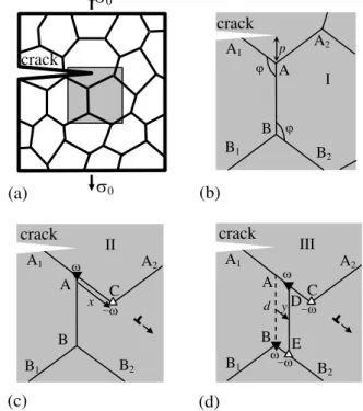
Fig. 3. Grain boundary deformation processes in nanocrystalline specimen near a crack tip. (a) General view. (b) Initial configuration I of grain boundaries. (c) Configuration II results from pure grain boundary sliding. Dipole of disclinations AC is generated due to grain boundary sliding. (d) Configuration III results from cooperative grain boundary sliding and migration process. Two disclination dipoles CD and BE are generated due to this cooperative process.
In the following, we will focus on the case of cooperative GB sliding and migration [52]. The geometry of this deformation mechanism is schematically presented in Fig. 3. Figure 3a depicts a two-dimensional section of a deformed nanocrystalline specimen. Within the proposed model [17,18], GB sliding occurs under the applied shear stress and transforms the initial configuration I of GBs (Fig. 3b) into configuration II (Fig. 3c). GB sliding is assumed to be accommodated, in part, by emission of lattice dislocations from triple junctions (Fig. 1c). Besides GB sliding results in the formation of a dipole of wedge disclinations A and C in configuration II (Fig. 3c) characterized by strengths , whose magnitude
is equal to the tilt misorientation of the GB AB [18] (AB is assumed to be a symmetric tilt boundary). The disclination dipole AC has an arm (the distance between the disclinations) equal to the magnitude x of the relative displacement of grains (Fig. 3c).We further assume [17] that in parallel with GB sliding, stress-driven GB migration occurs as well, so that the stress fields of defects created by GB sliding are, in part, accommodated by the defects created by GB migration. In the case shown in Fig. 3, the migration of the grain boundary AB into another position DE results in the formation of a quadrupole of wedge disclinations with the
crack
A
A1 A2
crack
p
I
A
A1 A2
crack
C
- x
II
A
A1 A2
crack
C
- y d
-
III B1
B
B2
B1 B2
B
B2
B1
(a) (b)
(c) (d)
B E
D
0
0
50 100 150 200 250 300
1 2 3 4
d, nm KIC
,
MPa m
1/2
-Fe
Al
strengths at the points A, B, D and E [17]. The disclination with the strength appearing at the point A due to GB sliding and the disclination with the strength appearing at the same point due to GB migration annihilate. The annihilation results in the disclination configuration shown in Fig. 3d. In general, the cooperative GB sliding and migration process transforms the initial configuration I (Fig. 3b) into the final configuration III (Fig. 3d). During this processes, in parallel with GB sliding that causes the relative displacement of grains over the distance x, stress-driven migration of the vertical GB occurs over the distance y from its initial position AB to the new position DE (Fig. 3d). The cooperative GB sliding and migration process leads to the formation of two disclination dipoles CD and BE (Fig. 3d). The disclination dipole CD of wedge disclinations is characterized by the strength magnitude and the arm |xy|. The disclination dipole BE is characterized by the strength magnitude and the arm y.
IV. EFFECTS OF COOPERATIVE GRAIN BOUNDARY MIGRATION AND SLIDING ON CRITICAL STRESS INTENSITY
FACTOR FOR CRACK GROWTH IN NANOCRYSTALLINE SOLIDS
Let us now consider the effect of the applied tensile load and a long flat mode I crack on the cooperative GB sliding and migration process (Fig. 3). The vertical GB is assumed to be normal to the crack growth direction and make an angle with the grain boundaries AA1 and BB2 (Fig. 3b). Let the triple junction A lie at a distance p from the crack tip and the length of all GBs in the initial state (Fig. 3b) be denoted as d. To calculate the parameters of the cooperative GB sliding and migration process, we have calculated the energy change W associated with the formation of the disclination configuration shown in Fig. 3d. The energy change W can be written [18] as
4 4
1 1
4 1
int
1 1
( , ) ( , )
( , , , )
j j j j j
j j
j
j k j k j k sl
j k
W W r s W r
s s W r r A
, (5)where (rj,j) are the coordinates of the jth disclination in
the polar coordinate system with the origin at the crack tip (j=1,2,3,4; see Fig. 1), and the rest of the symbols are defined as follows: W ( ,rj j)
is the energy of the jth disclination in the solid with a crack; W ( ,rj j)
is the energy of the interaction between the disclination with the strength , lying in the point (rj,j), and the stress field
il
induced by the applied load near the crack tip;
int( , ,j k j, k)
W r r is the energy of the interaction between the jth and kth disclinations (in the solid with a crack) assuming that both disclinations have the strength , and
sl
A is the work of the stress il done on GB sliding, which
does not account the formation of disclinations. The parameters sj in Eq. (5) account for the sign of a specified
disclination and are defined as s1s4 1, s2s3 1. The
first and third terms appearing in the left hand side of formula (5) have been calculated using the known
expressions [19] for the disclination self-energy and the energies of the interaction between disclinations in a solid with a flat semi-infinite crack, while the other two terms have been cast based on the expressions (e.g., [18]) for the stresses induced by a remote tensile load in a solid with such a crack. The minimum of the energy W corresponds to the equilibrium lengths xx0 and yy0 of GB sliding
and migration, respectively.
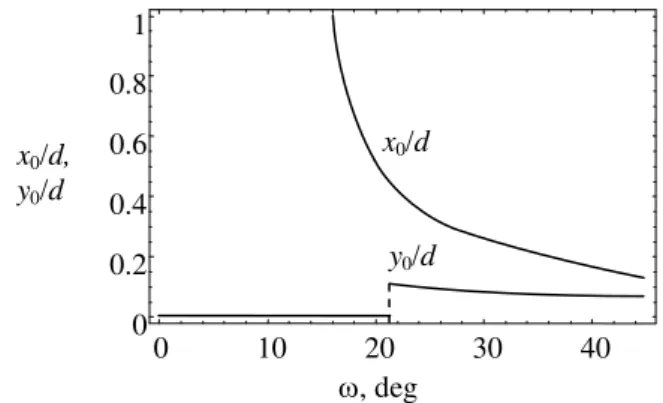
Fig. 4. Dependences of the normalized equilibrium lengths,
0/
x d and y0/d, of grain boundary sliding and migration,
respectively (near a crack tip in nanocrystalline Ni) on disclination strength .
The dependences of the parameters x0/d and y0/d on
the disclination strength are shown in Fig. 4 for the case of an intragrain crack in nanocrystalline Ni and the following typical values of parameters: br
I IC
K K (where
I
K is the stress intensity factor associated with the applied load 0, 4 / (1 )
br IC
K G is the fracture toughness for brittle fracture, and
is the specific surface energy), G=73 GPa, 0.31, 1.725 J/m2, 2/3, d=15 nm, p=0. As it is seen in Fig. 4, the equilibrium length of GB migration is small compared to the length of GB sliding. Numerical analysis shows, however, that at higher values of the stress intensity factor KI
the difference between the normalized equilibrium lengths x0/d and y0/d
diminishes, so that the contribution of GB migration (if such migration occurs) to the hindering of crack propagation increases. For large enough values of , the equilibrium lengths x0 and y0 gradually increase with decreasing
. Below a critical value of (21), the equilibrium length y0 of GB migration becomes equal to zero, whereasthe equilibrium length of GB sliding x0 increases very
rapidly with a decrease in , reaching the values close to the GB length d.
Now let us consider the effect of disclination configuration, resulting from the cooperative GB migration and sliding, on the fracture toughness of a nanocrystalline solid. To do so, we will use the standard crack growth criterion [20] based on the balance between the driving force related to a decrease in the elastic energy and the hampering force related to occurrence of a new free surface during crack growth. In the examined case of the plane
0 10 20 30 40
0 0.2 0.4 0.6 0.8 1
x0/d, y0/d
, deg x0/d
strain state, this criterion is given [20] by
2 2
1
2
2G KI KII
, (6) where KI (mode I) and KII (mode II) are the stress
intensity factors for normal (to crack line) and shear loading, respectively. In the considered situation where the crack growth direction is perpendicular to the direction of the external load, the coefficients KI and KII are given by the expressions
,
q q
I I I II II
K K k K k , (7) where
k
Iq andq II
k
are the stress intensity factors induced by the internal stresses created by the disclinations located near the crack tip (Fig. 3).Within the above macroscopic mechanical description, the effect of the local plastic flow – the cooperative GB migration and sliding mechanisms resulting in the formation of disclinations – on crack growth can be accounted for through the introduction of the critical stress intensity factor
IC
K . In this case, the crack is considered as propagating under the action of the tensile load perpendicular to the crack growth direction, while the presence of the disclinations simply changes the value of KIC
corresponding to the case of brittle crack propagation. In these circumstances, the critical condition for the crack growth can be represented as (e.g., [14]): KI KIC
. Upon substitution of Eq. (7) into Eq. (6) and use of the critical condition KI KIC
one finds the following expression for KIC [19]:
2 2
( br) ( q ) q
IC IC IIC IC
K K k k . (8) In Eq. (8) the various quantities are defined as follows:
|
I IC
q q
IIC II K K
k k and |
I IC
q q
IC I K K
k k . It should be noted that
the quantities q IIC
k and q IC
k depend on KIC, and, thus, Eq. (8) provides the appropriate formula for the determination of KIC.
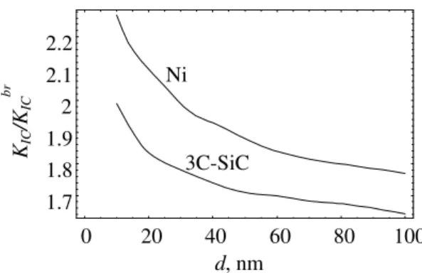
Now let us consider the effect of grain size on the critical stress intensity factor KIC. To do so, in Fig. 5 we have
plotted the dependences of / br
IC IC
K K on grain size d for the cases of GB cracks in nanocrystalline Ni and nanocrystalline ceramic 3C-SiC, at 30, pd and the other parameter values (typical of nanocrystalline Ni) specified above. For 3C-SiC we have used the following parameter values: G= 217 GPa, 0.23, 1.84. Fig. 5 demonstrates that as the grain size increases from 10 to 100 nm, the ratio / br
IC IC
K K decreases from 2.23 to 1.77, for Ni, and from 1.99 to 1.64, for 3C-SiC. Therefore, the suggested cooperative GB sliding and migration mechanism is most effective in increasing fracture toughness at smallest grain sizes, in contrast to lattice dislocation emission from crack tips – the conventional fracture toughness mechanism in metallic materials – whose effect on the fracture toughness of nanocrystalline metals rapidly increases with an increase in grain size (see Fig. 2).
Fig. 5. Normalized critical stress intensity factor / br IC IC
K K vs grain size d, in the case of a grain boundary crack in nanocrystalline Ni and 3C-SiC.
Thus, the results of the calculations show that cooperative GB migration and sliding along a single GB can make the critical stress intensity factor KIC several times larger.
Apparently, cooperative GB migration and sliding along various GBs can increase the value of KIC much further
and, as a result, may lead to a significant increase of fracture toughness, as compared to the case of pure brittle fracture. Also, Fig. 5 demonstrates that in the case where GB sliding and migration is the dominant deformation mechanism, KIC
decreases with increasing grain size. This is in contrast to the situation where the dominant deformation mechanism is lattice dislocation slip. In this situation KIC slightly
increases with grain size (see Fig. 2). Thus, if both lattice dislocation slip and the cooperative GB sliding and migration occur in a nanocrystalline solid, one can see the following tendency: for sufficiently small grain sizes the effect of lattice dislocation slip on fracture toughness should be small compared to that of the cooperative GB sliding and migration. At the same time, with an increase in grain size, the effect of the cooperative GB sliding and migration on fracture toughness becomes small compared to that of lattice dislocation slip. This means that at a critical grain size a transition from lattice-dislocation-mediated toughening to GB-deformation-produced toughening can occur in nanocrystalline solids.
V. SUMMARY
Thus, in this paper we have given a brief review of our studies of the effects of various deformation mechanisms of nanocrystalline solids on their fracture toughness. We have demonstrated that the cooperative GB sliding and migration can significantly (several times compared to the case of brittle fracture) increase the fracture toughness of nanocrystalline solids. Also, we have shown that GB sliding and migration is most effective in increasing fracture toughness of nanocrystalline metals with finest grains. As the grain size of a nanocrystalline metal increases, it is lattice dislocation slip that provides the principal contribution to fracture toughness enhancement.
REFERENCES
[1] J. D. Kuntz, G.-D. Zhan, and A. K. Mukherjee, “Nanocrystalline-matrix ceramic composites for improved fracture toughness,” MRS Bull., vol. 29, no. 1, pp. 22–27, Jan. 2004.
[2] A. Mukhopadhyay and B. Basu, “Consolidation-microstructure-property relationships in bulk nanoceramics and ceramic
0 20 40 60 80 100
1.7 1.8 1.9 2 2.1 2.2
KIC
/K
IC
b
r
d, nm Ni
nanocomposites: a review,” Int. Mater. Rev., vol. 52, no. 5, pp. 257– 288, Sept. 2007.
[3] R. A. Andrievski and A. M. Glezer, “Strength of nanostructures,” Physics – Uspekhi, vol. 52, no. 4, 337–358, April 2009.
[4] A.V. Sergueeva, D.M. Hulbert, N.A. Mara and A.K. Mukherjee, “Mechanical properties of nanocompopsite materials”, In
Nanostructured Materials, G. Wilde Ed. Elsevier, 2010, pp. 127–172. [5] S. C. Tjong and H. Chen, “Nanocrystalline materials and coatings,”
Mater. Sci. Eng. R, vol. 45, no. 1–2, pp. 1–88, Sept. 2004.
[6] C. C. Koch, I. A. Ovid’ko, S. Seal, and S. Veprek, Structural Nanocrystalline Materials: Fundamentals and Applications.
Cambridge: Cambridge University Press, 2007.
[7] D. Wolf, V. Yamakov, S. R. Phillpot, A. K. Mukherjee, and H. Gleiter, “Deformation of nanocrystalline materials by molecular-dynamics simulation: relationship to experiments?”, Acta Mater., vol. 53, no. 1, pp. 1–40, Jan. 2005.
[8] M. Dao, L. Lu, R. J. Asaro, J. T. M. De Hosson, and E. Ma, “Toward a quantitative understanding of mechanical behavior of nanocrystalline metals,” Acta Mater., vol. 55, no. 12, pp. 4041–4065, July 2007.
[9] C. C. Koch, “Structural nanocrystalline materials: an overview,” J. Mater. Sci., vol. 42, no. 5, 1403–1414, March 2007.
[10] G. E. Beltz, D. M. Lipkin, and L. L. Fischer, “Role of crack blunting in ductile versus brittle response of crystalline materials,” Phys. Rev. Lett., vol. 82, no. 22, 4468–4471, May 1999.
[11] M. Huang and Z. Li, “Dislocation emission criterion from a blunt crack tip,” J. Mech. Phys. Sol., vol. 52, no. 9, pp. 1991–2003, Sept. 2004.
[12] M. Creager and P. C. Paris, “Elastic field equations for blunt cracks with reference to corrosion cracking,” Int. J. Fracture, vol. 3, no. 4, pp. 247–252, April 1967.
[13] R. B. Figueiredo, M. Kawasaki, and T. G. Langdon, “The Mechanical Properties of Ultrafine-grained Metals at Elevated Temperatures,”
Rev. Adv. Mater. Sci., vol. 19, no. 1, pp. 1–12, March 2009.
[14] Fracture mechanics and strength of materials, V.V. Panasyuk Ed. Kiev: Naukova Dumka, 1974 (in Russian).
[15] I. A. Ovid’ko and A. G. Sheinerman, “Ductile vs brittle behavior of pre-cracked nanocrystalline and ultrafine-grained materials,” Acta Mater., vol. 58, no. 16, pp. 5286–5294, Sept. 2010.
[16] L. L. Fisher and G. E. Beltz, “The effect of crack blunting on the competition between dislocation nucleation and cleavage,” J. Mech. Phys. Sol., vol. 49, no. 3, pp. 635–654, March 2001.
[17] S. V. Bobylev, N. F. Morozov, and I. A. Ovid’ko, “Cooperative grain boundary sliding and migration process in nanocryystalline solids,”
Phys. Rev. Lett., vol. 105, no. 5, art. 055504, July 2010.
[18] I. A. Ovid’ko, A. G. Sheinerman, and E. C. Aifantis, “Effect of cooperative grain boundary sliding and migration on crack growth in nanocrystalline solids,” Acta Mater., vol. 59, no. 12, pp. 5023–5031, July 2011.
[19] N. F. Morozov, I. A. Ovid’ko, A. G. Sheinerman, and E. C. Aifantis, “Special rotational deformation as a toughening mechanism in nanocrystalline solids,” J. Mech. Phys. Solids, vol. 58, no. 8, pp. 1088–1099, Aug. 2010.