S. Tarasovs et alii, Frattura ed Integrità Strutturale, 35 (2016) 271-277; DOI: 10.3221/IGF-ESIS.35.31
271
Focussed on Crack Paths
Modelling of the fracture toughness anisotropy in
fiber reinforced concrete
S. Tarasovs, J. Kr
ū
mi
ņ
š, V. Tamužs
Institute of Polymer Mechanics, University of Latvia, Aizkraukles St. 23, Riga, LV-1006, Latvia tarasov@pmi.lv
ABSTRACT. Steel fiber reinforced concrete is potentially very promising material with unique properties, which currently is widely used in some applications, such as floors and concrete pavements. However, lack of robust and reliable models of fiber reinforced concrete fracture limits its application as structural material. In this work a numerical model is proposed for predicting the crack growth in fiber reinforced concrete. The mixing of the steel fibers with the concrete usually creates nonuniform fibers distribution with more fibers oriented in horizontal direction, than in vertical. Simple numerical models of fiber reinforced concrete require a priori
knowledge of the crack growth direction in order to take into account bridging action of the fibers, which depends on the fibers orientation. In proposed model user defined elements are used to calculate the bridging force during the course of the analysis when the crack starts to grow. Cohesive elements were used to model the crack propagation in the concrete matrix. In cohesive zone model the cohesive elements are embedded between all solid elements to simulate the arbitrary crack path. The bridging effect of the fibers are modeled as non-linear springs, where the stiffness of the springs is defined from experimentally measured pull-out force and the angle between the fiber and crack opening direction.
KEYWORDS. Fiber reinforced concrete; Fracture; Cohesive elements.
INTRODUCTION
n recent years concrete reinforced by short steel fibers became very popular material in such applications as floors and concrete pavements. However, lack of robust and reliable models of fiber reinforced concrete fracture, limits its application as structural material.
The fracture of fiber reinforced concrete is complex phenomenon occurring at different length scales. Different models were proposed in the last years for the prediction of the fracture process in the fiber reinforced concrete. One of the most common approaches is cohesive zone model where the traction-separation law for the fiber-reinforced concrete is derived by averaging the pull-out forces of all fibers crossing the fracture plane [1]. Such models work well for sufficiently
homogeneous distribution of fibers and in situations, where direction of crack growth can be predicted a priori. More
complex models, which take into account the effect of individual fibers, may be necessary in other cases. Only few works with such models were published recently. The 2D and 3D lattice model with cement matrix, aggregates and discrete steel fibers was used in [2] to simulate the fracture behavior of fiber-reinforced concrete. Cunha et al. [3] used 3D smeared crack model to simulate concrete cracking and the truss elements were used to model the bridging action of steel fibers. Radtke et al. [4] used the damage model for matrix material and the steel fibers were indirectly modeled as traction forces
S. Tarasovs et alii, Frattura ed Integrità Strutturale, 35 (2016) 271-277; DOI: 10.3221/IGF-ESIS.35.31
272
mapped to the neighbor nodes of the background mesh. In this approach the mesh refinement around fibers is not necessary and the total number of degrees of freedom in the system remains unchanged.
In present work two-scale numerical approach within finite element framework is proposed. The concrete matrix fracture is simulated using cohesive zone model. The cohesive elements in current model are embedded between all solid elements, as a result the crack growth direction is chosen automatically during the analysis, minimizing the potential energy of the model. The effect of reinforcing fibers is modeled using non-linear spring elements, connecting nodes of neighboring solid elements at the location of the fiber. The properties of the spring elements are defined using experimentally obtained pull-out characteristics of single fibers embedded in concrete matrix at different angles. This model allows to simulate the initiation and propagation of the crack, taking into account the non-uniform spatial distribution of reinforcing fibers.
FINITE ELEMENT MODEL
omplex nature of the reinforced concrete failure, involving the cracking of the concrete matrix and steel fiber debonding from concrete matrix and pull-out, does not allow to model this process explicitly. Therefore simplified two-scale approach within the framework of finite element method was used. Two major mechanisms of fracture, matrix cracking and fiber pull-out were modeled independently. The approach suggested in [5] was used to model the fracture of the heterogeneous concrete material without prior knowledge of the crack path. In this model the cohesive elements are embedded between all solid elements, thus allowing automatic formation of the fracture surface during the simulations. In-house Perl script was written for the cohesive elements embedding procedure. Input file generated by the finite element code ABAQUS and containing solid 3D model with defined surfaces, sets and boundary conditions is automatically transformed into new modified model with cohesive elements embedded between solid elements in the middle part of the specimen, where the crack is expected to grow. The procedure of cohesive elements embedding is shown in Fig. 1: at first solid elements are separated by creating duplicate nodes with the same coordinates, then these elements are connected by zero-thickness cohesive elements. The procedure takes care of converting all predefined sets, surfaces and boundary conditions, using new nodes, and generates new input file, which can be directly solved by ABAQUS explicit solver.
Figure 1: Procedure of embedding cohesive elements: original FE mesh; separated elements with duplicate nodes; cohesive elements embedded between all solid elements.
Due to small size and large number of steel fibers, the fibers are not modeled explicitly. The fibers bridging action is approximately modeled by a number of non-linear springs, embedded into finite element mesh at the fibers location. The same Perl script randomly distributes steel fibers in the specimen’s volume, taking into account experimentally measured orientation of fibers [6], finds the elements faces, crossing the fiber, and connects these faces with non-linear spring elements, as shown in Fig. 2. The spring’s stiffness takes into account the fiber pull-out forces, obtained experimentally or using some simplified analytical model [7].
In many situations the general crack growth direction is known a priori and the angle between the fiber and pulling force
and, therefore, the spring’s stiffness, can be estimated before the analysis. However, if the crack growth direction is not known, the spring’s stiffness has to be determined during the analysis, taking into account the local crack opening direction and fiber orientation, as shown in Fig. 3. This can be done using user defined element or similar approach, depending on finite element software used.
S. Tarasovs et alii, Frattura ed Integrità Strutturale, 35 (2016) 271-277; DOI: 10.3221/IGF-ESIS.35.31
273 Figure 2: Steel fiber modeling by non-linear springs.
Figure 3: Determination of the fiber orientation angle.
EXPERIMENTAL PART
ver decades many works have shown the advantages of fiber reinforced concrete (FRC)[8]. In FRC the amount and shape of the steel fibers plays an important role on composites mechanical properties. In this study 2% volume fraction of “hook-end” steel fibers is chosen. Commercially available steel fibers HE 75/50 were used with geometrical parameters shown in Tab. 1 and Fig. 4.
Fiber diameter, d 0.75 ± 0.04 mm
Fiber length, L 50.0 ± 3 mm
Hook length, l and l’ 1 – 4 mm
Table 1: Parameters of hooked steel fiber used in experiments.
Figure 4: Geometry of steel fiber HE 75/50 used in experiments.
It is well known that fibers orientation has large effect on the structural strength of fiber-reinforced concrete [9], [10]. In order to evaluate single fiber and matrix interfacial properties, single fiber pull-out tests (SFPT) were performed. The fibers embedded in half of total fiber length (L) were located at different angles (0, 20, 40 and 60 degrees) according to the
S. Tarasovs et alii, Frattura ed Integrità Strutturale, 35 (2016) 271-277; DOI: 10.3221/IGF-ESIS.35.31
274
applied load. As was shown in previous studies, the embedded depth of the “hook-end” fiber (H) has relatively small effect on the pull-out force [11, 12]. Experimental scheme and resulting pull-out force are shown in Fig. 5. Experimental pull-out curves show that maximal pull-out load is achieved at 40 degrees, other authors have shown, that the maximum peak load is attained at 45 degree inclination [13]. Lower stiffness and increased displacement at maximal force for fibers embedded in 60 degree could be explained by matrix spalling and fiber bending.
Figure 5: Experimental scheme and single fiber pull-out force at different angles.
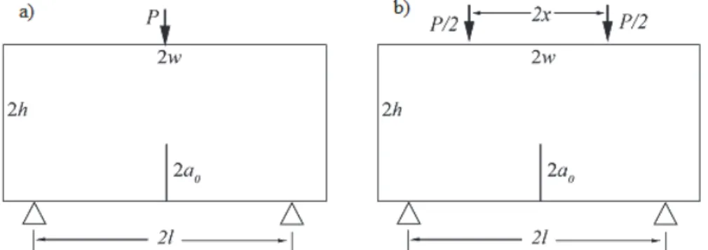
In present work 3-point and 4-point bending tests were used to characterize concrete elements reinforced by steel fibers. 3-point bending tests were used to determine mechanical properties of plain concrete. In order to evaluate the influence of steel fibers on concrete strength, four-point-bending tests with larger specimens were conducted. 3-point and 4-point bending test are schematically shown in Fig 6. Commercially available concrete matrix “Sakret C25” (compressive strength 25 MPa) was used to mix the specimens, with maximal grain diameter equal 8mm and water content 1l/10kg. Specimens were tested 28 days after material mixing.
Figure 6: Geometry and loading scheme of a) 3-point bending test, b) 4-point bending test.
Dimensions of specimens are shown in Tab. 2. Specimens had an initial crack with length 2a0. The results of 3-point
S. Tarasovs et alii, Frattura ed Integrità Strutturale, 35 (2016) 271-277; DOI: 10.3221/IGF-ESIS.35.31
275
3-point bending test (Fig. 2a)
2h Height , cm 7.5
2b Width, cm 7.5
2w Length, cm 30
2a0 Initial crack length, cm 2
2l Support separation, cm 28
4-point bending test (Fig. 2b)
2h Height, cm 15
2b Width, cm 15
2w Length, cm 60
2a0 Initial crack length, cm 4
2l Support separation, cm 45
2x Load separation, cm 15
Table 2: Geometrical parameters of the specimen.
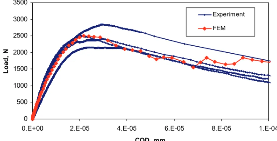
0 500 1000 1500 2000 2500 3000 3500
0.E+00 2.E-05 4.E-05 6.E-05 8.E-05 1.E-04
COD, mm Loa d, N Experiment FEM
Figure 7: Load-crack opening displacement diagram of a three point bending test for plain concrete beam. Numerical and experimental curves.
RESULTS OF NUMERICAL SIMULATIONS
s an example the wedge splitting test [14] will be simulated using proposed approach. The specimen’s size is
202030 cm with initial crack depth equal 15 cm. Previous studies show [15], that due to vibration during
specimen’s preparation stage, the fibers tend to be aligned horizontally and there are much less vertical fibers. This deviation from uniform random distribution creates anisotropy of the fracture toughness of the fiber reinforced concrete. As a result, the crack may grow in unexpected direction and simple models are unable to predict such behavior. Fig. 8 shows two possible modes of failure of plain concrete and fiber reinforced concrete. The plain concrete has isotropic fracture toughness and crack typically grow downward, as it is expected. In the fiber reinforced concrete the horizontal cracks are more favorable, and in some situations the crack may turn and grow toward the side of the specimen. To prevent such behavior, deeper initial notch and/or side grooves can be used.
Proposed numerical model was used to simulate the failure of notched fiber reinforced concrete specimen in 4-point bending tests (Fig. 9). The results of simulation are shown in Fig. 10, compared with experimental curves. The numerical results show substantially higher reinforced concrete strength, which can be explained by the fibers interaction and non-uniform distribution of fibers in the specimen. The numerical model does not take into account the interaction between individual fibers: when fibers are located too close to each other, the total pull-out force could be less, than the sum of forces of individual fibers, which was measured in single fiber pull-out test.
S. Tarasovs et alii, Frattura ed Integrità Strutturale, 35 (2016) 271-277; DOI: 10.3221/IGF-ESIS.35.31
276
Figure 8: Possible failure modes of plain concrete (on the left) and fiber reinforced concrete (on the right).
Figure 9: Simulation of the fiber reinforced concrete specimen failure in 4-point bend test.
0.0E+00 5.0E+03 1.0E+04 1.5E+04 2.0E+04 2.5E+04 3.0E+04
0.0E+00 5.0E-04 1.0E-03 1.5E-03 2.0E-03
COD, mm
Lo
ad,
N
Experiment FEM
S. Tarasovs et alii, Frattura ed Integrità Strutturale, 35 (2016) 271-277; DOI: 10.3221/IGF-ESIS.35.31
277
CONCLUSION
n this work a two-scale finite element model is proposed for the simulation of the fiber reinforced concrete failure. The model uses cohesive elements to simulate the cracking of the concrete matrix, whereas the bridging action of steel fibers is approximated by non-linear springs, connecting the nodes on the opposite faces of the crack. The stiffness of these non-linear spring elements directly takes into account the orientation of individual fibers and crack growth direction, allowing to model anisotropy of the fracture toughness of fiber reinforced concrete.
The results of simulations show that the spatial distribution of fibers orientations may have substantial effect on the crack propagation direction.
ACKNOWLEDGEMENT
his work has been funded by the Latvian Ministry of Education and Science via project Nr. 214/2012.
REFERENCES
[1] Jones, P.A., Austin, S.A., Robins, P.J., Predicting the flexural load–deflection response of steel fibre reinforced
concrete from strain, crack-width, fibre pull-out and distribution data, Mater. Struct., 41 (2007) 449–463.
[2] Kozicki, J., Tejchman, J., Effect of steel fibres on concrete behavior in 2D and 3D simulations using lattice model,
Arch. Mech., 62 (2010) 465–492.
[3] Cunha, V.M.C.F., Barros, J.A.O., Sena-Cruz, J.M., An integrated approach for modelling the tensile behaviour of
steel fibre reinforced self-compacting concrete, Cem. Concr. Res., 41 (2011) 64–76.
[4] Radtke, F.K.F., Simone, A., Sluys, L.J., A computational model for failure analysis of fibre reinforced concrete with
discrete treatment of fibres, Eng. Fract. Mech., 77 (2010) 597–620.
[5] Xu, X.-P., Needleman, A., Numerical simulations of fast crack growth in brittle solids, J. Mech. Phys. Solids, 42
(1994) 1397–1434.
[6] Tarasovs, S., Zile, E., Tamuzs, V., Experimental and numerical investigation of steel fiber reinforced concrete
fracture, Proc. of 19th European Conference on Fracture, Kazan, Russia, 26-31 (2012) 6.
[7] Zīle, E., Zīle, O., Effect of the fiber geometry on the pullout response of mechanically deformed steel fibers, Cem. Concr. Res., 44 (2013) 18-24.
[8] Zollo, R.F., Fiber-reinforced concrete: an overview after 30 years of development, Cem. Concr. Compos., 19 (1997)
107-122.
[9] Ferrara, L., Ozyurt, N., Prisco, M., High mechanical performance of fibre reinforced cementitious composites: the
role of “casting-flow induced” fibre orientation, Mater. Struct., 44 (2011) 109–128.
[10] Barnett, S.J., Lataste, J.-F., Parry, T., Millard, S.G., Soutsos, M.N., Assessment of fibre orientation in ultra high
performance fibre reinforced concrete and its effect on flexural strength, Mater. Struct., 43 (2009) 1009–1023. [11] Robins, P., Austin, S., Jones, P., Pull-out behaviour of hooked steel fibres, Mater. Struct., 35 (2002) 434–442.
[12] Cunha, V.M.C.F., Barros, J.A.O. & Sena-cruz, J.M., Pullout Behavior of Steel Fibers in Self-Compacting Concrete, J. Mater. Civ. Eng., 22 (2010) 1–10.
[13] Morton, J., Groves, G.W., The cracking of composites consisting of discontinuous ductile fibres in a brittle matrix-
effect of fibre orientation, J. Mater. Sci., 9 (1974) 1436-1445.
[14] Bruhwiler, E., Wittman, F. H., The wedge splitting test, a new method of performing stable fracture mechanics tests,
Eng. Fract. Mech., 35 (1990) 117–125.
[15] Robins, P., Austin, S., Jones, P., Spatial distribution of steel fibres in sprayed and cast concrete, Mag. Concr. Res., 55 (2003) 225–235.