© 2014 Science Publications
doi:10.3844/jcssp.2014.1703.1711 Published Online 10 (9) 2014 (http://www.thescipub.com/jcs.toc)
Corresponding Author: A. Selwin Mich Priyadharson, School of Electrical, Vel Tech University. Chennai, India
JCS
ENERGY EFFICIENT FLOW AND LEVEL CONTROL
IN A HYDRO POWER PLANT USING FUZZY LOGIC
1
A. Selwin Mich Priyadharson,
2M.S. Saravanan,
3
N. Gomathi,
4S. Vinson Joshua and
5A. Mutharasan
1,4,5
School of Electrical, Vel Tech University, Chennai, India
2,3
School of Computing, Vel Tech University, Chennai, India
5
School of Electrical, Vel Tech High Tech Engineering College, Chennai, India
Received 2013-04-12; Revised 2014-02-19; Accepted 2014-04-19
ABSTRACT
The main objective and an innovative design of this work is to improve the energy efficiency by controlling the variables flow and level in a hydroelectric power plant using Programmable Logic Control (PLC)-Human Machine Interface (HMI) and fuzzy logic approach. This project will focus on design and development of flow and level controller for small scale hydro generating units by implementing gate control based on PLC-HMI and Fuzzy Logic Control (FLC). So far there is no other better performing control scheme, with uncomplicated approach, in order to match and satisfy the dynamic changes in load demand. In this project, FLC will be applied to flow and level control for small scale hydro generating units is proposed. A lab scale experimental setup is made-up as prototype model for flow and level control and simulation outputs were achieved, using PLC-HMI based fuzzy controller scheme. The hardware set up is designed with 5 stages in the tank 1 and 2 stages in the tank 2. Based on the outputs of the level sensors from tanks 1 and 2, the ladder logic will perform. B&R Industrial Automation PLC inbuilt with 24 digital inputs and provides 16 potential free outputs is used to perform control action. Finally, the performance of the proposed scheme is evaluated by simulation results by comparing with conventional controllers output using the data collected from the hydroelectric power plant. The merits of the proposed Fuzzy scheme over the conventional method are spotlighted.
Keywords: FLC, Hydropower Plant, Ladder Logic, Level Sensor, PLC-HMI
1. INTRODUCTION
Hydro electric power is a main source of renewable energy for power generation. Nowadays for world energy requirement hydro electric power is intensifying as a major contributor
Conversion of potential energy of water into electricity takes place in hydroelectric power plant. The production of energy is based on the available water flow and altitude it plummets (Rajeswari et al., 2012). To manage the drawbacks of conventional type such as Ecosystem damage, siltation, flow shortage, methane emissions, automation is preferable (Guo, 2009).
Rajeswari et al. (2012) highlighted on controlling the variables level and flow with real time
implementation of gate control in hydroelectric power plant using PLC. Liang (2000) proposed a methodology derived from neural network in hydro power production using pumped-storage units. King et al. (2001) discussed the governor control in a pumped storage hydroelectric plant using Fuzzy Inference System (FIS). Rabelo et al. (2012) proposed the implementation of Reservoir Operation Rules (ROR) using fuzzy and Particle Swarm Optimization (PSO).
(2012) explained that the fuzzy logic method is very useful for problem solving approach in small hydro power generation. The rule base and membership functions have a great influence on the performance and efficacy of the plant and also to optimize the small hydro power generation in the high altitude region. Yadav et al. (2011) presented the TSK fuzzy controller in order to maintain water level constant in run-of-river hydro power plant. Nanhua and Xiaoju (2010) presented a nonlinear dynamic model depending on the behavior of the hydroelectric units with hydraulic interconnection in nonlinear condition and they developed adaptive fuzzy controller based on that model.
Singh and Chauhan (2011) described that in hydrothermal power plant an exact signal is necessary to manipulate the gate that has to be identified and it will match the requirement of sudden large change in the loads. Also he described that the maximum sudden increase and decrease in load system has to be expected and consequent manipulation in gate position has to be well-known.
And also with the intention of enhance, the performance of the hydroelectric power plant, the PLC-HMI based fuzzy controller scheme is developed. The PLC-HMI based fuzzy controller scheme for water flow and level control is proposed. The present paper is structured as follows: Section 2 deals with process and prototype model description. Section 3 deals with the conventional scheme for hydroelectric power plant. Section 4 describes PLC-HMI based fuzzy controller scheme. Section 5 describes the Visualization. Section 6 describes the simulation studies of conventional and PLC-HMI based fuzzy controller for flow and level control. Section 7 gives the summary and conclusions.
2. PROCESS AND PROTOTYPE
MODEL DESCRIPTION
Electricity demand will not be steady at all times. Power demand will increase and decrease during day time and there is less demand for electricity in domestic applications, business and other facilities at over night. In order to manage the high load demand, pumped storage is necessary.
Pumped storage is maintaining water in reserve for high load demand by pumping water that has previously flow through the turbines. Because of this pumped storage method of reusing the water more than once, hydroelectric power plants is the efficient source during high load than other power plants.
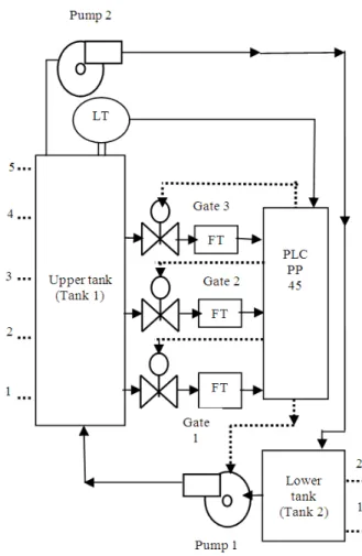
The Operation of prototype model is represented in Fig. 1.
Fig. 1. Operation of prototype model
There are two tanks in the lab scale experimental set up. There are 5 stages in tank 1 and two stages in tank 2 (Rajeswari et al., 2012).
The five stages in tank 1 are:
• Low level
• Average level
• Medium level
• High level
• Danger level
The two stages in tank 2 (Rajeswari et al., 2012) are:
• Low level
• High level
When the water level in the tank 2 reaches the low level, the pump 1 is actuated and the water is taken to the tank 1 from the tank 2. In tank 1 when the water level reaches the low level pump 1 is again switched on and water level raises up to average level. When water exceeding average level, Gate 1 is allowed to open. Similarly when the level attains medium level, the pump 1 actuated and the water raises up to high level.
When water is mounting beyond medium level, Valve 1 and 2 is opened and when water level is exceeding beyond high level, Valve 1, 2 and 3 is opened. When the level exceeding beyond the danger level, the pump2 is actuated and water is taken back to lower tank. If the water level reaches high level in tank 1, Valve 1, 2 and 3 will be closed and also the pumps 1 and 2 will be switched off. Based on the Level Transmitter (LT) output the ladder logic is programmed and as per the programmed ladder logic, the pumps and also the opening of valves of the lab scale experimental set up are actuated at their respective stages. The Block diagram of Hardware set up is shown in Fig. 2 which consists of the following hardware components:
• Programmable logic controller
• FT-Flow Transmitters
• LT-Capacitive Level Transmitter
• Pumps
• Valves
Fig. 2. Block diagram of hardware set up
The Lab scale Experimental set up is regulated based on the above mentioned sequences. The Lab scale Experimental set up is shown in Fig. 3.
3. CONVENTIONAL SCHEME FOR
HYDROELECTRIC POWER PLANT
Figure 4 represents the B&R Industrial Automation PLC.
Using this PLC the control action is performed for maintaining the level in the tank and flow rate to the turbine based on load demand. B&R Industrial Automation PLC inbuilt with 24 digital inputs and provides 16 potential free outputs is used to perform control action.
Fig. 3. Lab scale experimental set up
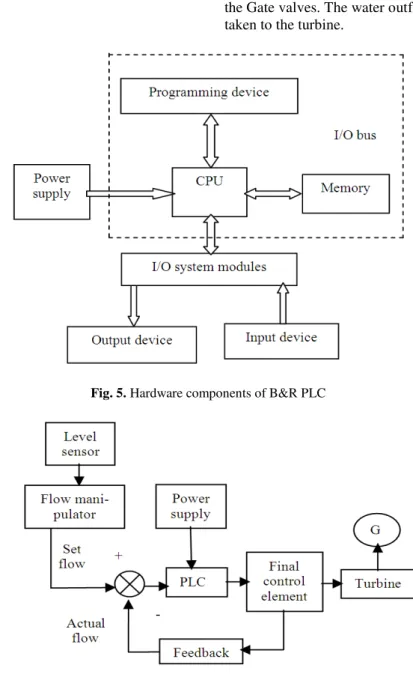
Here this PLC is utilized for automation in small hydroelectric plant depending on the operational requirements. The Hardware components of B&R PLC system is shown in Fig. 5. It has:
• Processor Unit (CPU)
• Memory section
• Input/output sections
• Power supply unit
• Programming device
• System buses
In Fig. 6. Block diagram for flow control in Hydro Plant is represented. Gates (final control element) will open/close in hydro electric plant depending on the water level in the reservoir.
The water level in the reservoir is measured by capacitive level sensor. The actual level value is manipulated to the flow set point by using flow manipulator. Comparison between desired water flow and actual flow rate is done and the deviation is controlled by PLC which gives manipulated variable to the Gate valves. The water outflow from the gate valve is taken to the turbine.
Fig. 5. Hardware components of B&R PLC
4. PLC-HMI BASED FUZZY
SCHEME FOR HYDRO PLANT
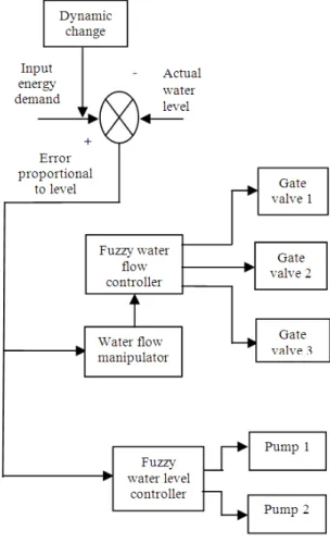
The proposed PLC-HMI based fuzzy scheme for flow and level control is shown in the Fig. 7.
During start up power obtained is opposite to the direction of change in valve position. When sudden open in gate is done because of water inertia the flow will not do immediate change instead of that the pressure across the turbine will reduce consistently making power to reduce. When sudden increase or decrease in load occurs the water accelerates until the water flow settles to the new desired value (Falqueto and Telles, 2007).
Because of the sudden increase and decrease in load the gate opening/closing operation may have limitation in speed deviation but it formulate damages to turbine/generator shaft. If slow and smooth operation of gate is preferred to prevent this type of damages that will leads to lagging in load due to low pick up of the turbine/generator and also the drop in frequency will occur. So it is necessary to get (Falqueto and Telles, 2007) a suitable signal so that to operate the gate which will satisfy the sudden load change and also to maintain the constant speed, the proposed PLC-HMI based fuzzy scheme is done. Thereby the maximum sudden in and out of load change is expected and equivalent manipulation in valve position is obtained using the proposed scheme. The opening and closing of the gate position is done in three types. It is step closing/opening for sudden change, ramp closing/opening for velocity and exponential opening/closing for acceleration.
Two fuzzy controllers are used for water flow and water level control. Fuzzy water level controller inputs are the error and change in error. Similarly inputs to the Fuzzy water flow controller are derived with respect to the error in water level. The FLC implemented for hydro power plant has two inputs and one output for water flow and level respectively. Error and change in error are the inputs are and the output is the variation in pump speed or OFF condition for the water flow. The universes of discourse of the controller variables are E, ∆E and U respectively.
The triangular membership functions are used to represent the linguistic terms (VS = Very small; S = Small; M = Medium; L = Large; VL = Very Large). Rule base is developed and an inference mechanism is designed using Mamdani (min-max) method that gives the output signal to the final control elements. The output of the inference mechanism is a fuzzy value and is converted into crisp value using centroid method for defuzzification. The parameters of the FLC system designed for the hydro electric power plant are presented in Table 1.
Fig. 7. PLC based fuzzy controller scheme
Table 1. FLC parameters for flow and level controller
Parameters Flow control Level control Input variables 2 2
Fuzzy sets 5 5
Rules 18 20
Membership function Triangular Triangular Defuzzyfication method Centroid Centroid
5. VISUALIZATION
Visualization is the process of designing a Human Machine Interface (HMI) used to operate the PLC with ease. A variety of devices have been in past for interfacing the machine to provide an easy control of the operations. The most modern technique involves the use of touch screen to give the inputs.
using the screens. Whenever any operations are being performed it is displayed on the screen and thus enables the user to keep track of what is happening.
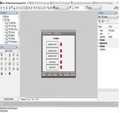
Figure 8 represents the hydro electric plant proto type in HMI. By seeing this, Hardware set up operation in HMI can be able to understand, monitor and supervise the operation and if mistake occurs rectification in the process can also be done.
Figure 9 represents start/stop button in HMI for the designed prototype model. The process can be start/stop at any time by pressing the button. Figure 8 represents the whole working operation of the hardware set up in online by using PLC-HMI.
Figure 10 represents the actuation of valves 1, 2, 3, pumps 1 and 2 in HMI. This display indicates the particular valve or pump which is set in motion presently.
Fig. 8. HMI displays hardware set up operation
Fig. 10. HMI displays valves and pumps operation
Software for creating the visualization are specific for a PLC and provided by the B&R Industrial Automation Pvt. Ltd (Austria). Thus the software automation studio, proprietary software for the PLC is used along with it.
The automation studio provides a user friendly interface for creating and calibrating the touch screens. It has various dynamic features such as profiler, logger and program watch that helps the user to carry in the programming task as well with ease and it helps for the easy correction of the mistakes made.
6. SIMULATION STUDIES
Plenteous experiments were conducted on the proto type model and the performances for both changes in the set point as well as in the load perturbation were studied. The responses obtained for up and down step variation in load for conventional and fuzzy scheme in hydroelectric power plant are shown in Fig. 11-13.
Comparisons of time domain specifications such as Rise time, peak time and settling time for conventional and the proposed PLC-HMI based fuzzy scheme was done. Similarly the performance evaluation criteria such as Integral Square Error (ISE) and Integral Absolute Error (IAE) was done for both conventional and the proposed scheme PLC-HMI based fuzzy for various step changes in load and it is presented in Table 2 and 3.
Fig. 11. Load 10 MW-20 MW Valve 1 opening above average level set point 20-40 m3/sec
Table 2. Comparisons of performance evaluation criteria
Load 10MW-20MW Load 40MW-60MW
--- --- Control scheme Control loop ISE IAE ISE IAE Conventional PLC Water flow 9832 8784 9544 8465 PLC-HMI based fuzzy Water flow 7355 7526 7495 7189
Table 3. Comparisons of time domain specifications
Load 10MW-20MW Load 40 MW-60MW
--- --- Control scheme Control loop Rise time Peak time Setl time Rise time Peek time Setl time Conventional PLC Water Flow 30 34 37 31 34 35 PLC - HMI based Fuzzy Water Flow 20 26 32 15 17 20
Fig. 12. Load 20 MW-40 MW Valve 2 Opening at medium level Set Point 40-60 m3/sec
Fig.13. Load 40 MW-60 MW Valve 3 opening at high level set point 60-85 m3/sec
Similarly analyzing the Performance Evaluation criteria, the conventional method has large ISE and IAE errors when compared with the proposed scheme. This highlights the better performance of PLC-HMI based Fuzzy than conventional control scheme.
7. CONCLUSION
The result of this real time work emphasizes the robustness of the PLC-HMI based fuzzy controller scheme for step variation in loads. The response of conventional control system has 24% overshoot for water flow. It settles down after about 65 steps of increment for water flow. The closed loop response of the PLC-HMI based fuzzy water flow controller scheme shows satisfactory transient response without much overshoot and reaches steady state after about 50 steps of increment for water flow.
This proposed PLC-HMI based fuzzy controller scheme shows 42% improvement over conventional schemes in settling time for water flow by having least ISE and IAE values for the step changes in load showing 15% improvement for water flow when compared to conventional schemes. The qualitative and quantitative evaluation of the performance of the various control schemes exposes the supremacy of the PLC-HMI based FLC scheme over the conventional schemes. There would be some limitations such as time delay in the proposed scheme during dynamic load change but it could be overcome by cascade scheme as future scope of this project.
8. REFERENCES
Atmojo, R.N.P., Anindito, B. Pardamean, B.S. Abbas and A.D. Cahyani et al., 2014. Fuzzy simple additive weighting based, decision support system application for alternative confusion reduction strategy in smartphone purchases. Am. J. Applied
Sci., 11: 666-680. DOI:
10.3844/ajassp.2014.666.680
Bai, V.R. and M.R. Tamjis, 2007. Fuzzy logic model on operation and control of hydro-power dams in Malaysia. ICCES, 4: 31-39.
Falqueto, J. and M.S. Telles, 2007. Automation of diagnosis of electric power transformers in Itaipu Hydroelectric Plant with a fuzzy expert system. Proceedings of the IEEE Conference on Emerging Technologies and Factory Automation, Sept. 25-28, IEEE Xplore Press, Patras, pp: 577-584. DOI: 10.1109/EFTA.2007.4416821
Guo, L., 2009. Design projects in a programmable logic controller course in electrical engineering. Technol. Interface J.
King, D.J., D.A. Bradley, S.P. Mansoor, D.I. Jones and F.C. Aris et al., 2001. Using a fuzzy inference system to control a pumped storage hydro plant. Proceedings of the 10th IEEE International Conference on Fuzzy Systems, Dec. 2-5, IEEE Xplore Press, pp: 1008-1011. DOI: 10.1109/FUZZ.2001.1009132
Liang, R.H., 2000. A noise annealing neural network for hydroelectric generation scheduling with pumped-storage units. IEEE Trans. Power Syst., 15: 1008-1013. DOI:10.1109/59.871726
Nanhua, L. and Y. Xiaoju, 2010. The adaptive fuzzy controller of hydroelectric units with hydraulic interconnection. Proceedings of the Chinese Control and Decision Conference, May 26-28, IEEE Xplore Press, Xuzhou, pp: 3998-4003. DOI: 10.1109/CCDC.2010.5498432
Rabelo, R.A.L., R.A.S. Fernandes and I.N. Silva, 2012. Operational planning of hydrothermal systems based on a fuzzy-PSO approach. Proceedings of the IEEE Congress on Evolutionary Computation, Jun. 10-15, IEEE Xplore Press, Brisbane, QLD, pp: 1-8. DOI: 10.1109/CEC.2012.6256596
Rajeswari, V., Y. Rajeshwari and L.P. Suresh, 2012. Real-time implementation of hydroelectric power plant using PLC and SCADA. Int. J. Eng. Res. Applic., 2: 899-902, 2012.
Singh, G. and D.S. Chauhan, 2011. Simulation and modeling of hydro power plant to study time response during different gate states. Int. J. Adv. Eng. Sci. Technol., 10: 042-047.
Umamahesh, N.V. and S. Chandramouli, 2006. Fuzzy dynamic programming model for optimal operation of a multipurpose reservoir. J. Water Resources Plann. Manage., 18: 14-20.