Design and Simulation of Fuzzy Logic
controller for DSTATCOM
In Power System
Anju Gupta
Department of Electrical and Electronics Engg.
YMCA University of Science and Technology [email protected]
P. R. Sharma
Department of Electrical and Electronics Engg. YMCA University of Science and Technology
[email protected] Abstract
In this paper design of self tuned fuzzy set theory based PI controller is incorporated in typical FACTS device DSTATCOM. Its effects are tested in power systems. The modeling and the controller block diagram for DSTATCOM with detailed design of self tuned fuzzy logic controller is presented. The performance of proposed fuzzy logic DSTATCOM has been simulated for current balancing and harmonic compensation for both linear and non-linear loads. The results show the capability of proposed model in enhancing the dynamic behavior of interconnected systems. The simulation is carried out in MATLAB SIMULINK and the results shows the results confirm the feasibility of proposed system.
KeywordsFuzzy logic controller; DSTATCOM; FACTS device.
1. Introduction
The FACTS (Flexible AC Transmission Systems) technology [1] is a new research area in power engineering. It introduces the modem power electronic technology into traditional ac power systems and significantly enhances power system controllability and transfer limit. In this paper, the static synchronous compensator (DSTATCOM) [2-4] and fuzzy logic control will be used to improve power system dynamic behavior after a system disturbance; DSTATCOM is based on a voltage-source inverter. The inverter under proper control can manage the capacitor, i. e. the dc voltage source, to be charged (or discharged) to the required voltage level. In this way, or by PWM controller, the amplitude of the output voltage of the inverter can be controlled for the purpose of reactive power generation or absorption. The control strategy is very important to the operation of DSTATCOM in order to yield desired steady state performance and improve the integrated system dynamic behavior.
2. System configuration
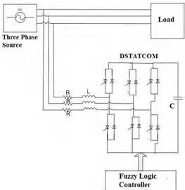
Fig.1. shows the basic circuit diagram of three phase three wire distribution system with unbalanced and nonlinear load and the DSTATCOM with fuzzy logic controller.
Fig. 1. Block diagram of system
The DSTATCOM consists of a three-phase pulse width modulated (PWM) voltage-source converter (VSC) using six insulated-gate bipolar transistors (IGBTs), three interface inductors, and one dc capacitor. The DSTATCOM injects currents into the point of common coupling in such a way so as to maintain balancing and harmonic elimination in the source currents. The VSI operation is supported by the dc storage capacitor with voltage across it.
3 Modeling of control scheme (SRF algorithm) of DSTATCOM
SRF theory is based on the transformation of currents in synchronously rotating d-q frame. The d-q component of load currents are computed from following relations
Fig.2. Block diagram of SRF algorithm
The average values of iLd and iLq are obtained form the low pass filters as iLddc and and iLqdc and id and iq are the output of the DC voltage PI controller and AC voltage PI controller.
The desired reference source currents in d-q frame are obtained as:
Isd= ilddc+id (1) Isq= ilqdc+iq (2)
Where isd and isq are the estimated DC components of active and reactive currents of reference source currents in d-q frame.
4 Design of self –tuned fuzzy PI controller
The fuzzy PI controller is driven by a set of control rules rather than by two constants proportional and integral gains. Fuzzy controller has data base and rule base, the function of data base is to provide necessary information to the rule base in the form of membership functions. The basic function of rule base is to represent the control policy of control engineer in the form of set of production rules as
If (process operator) then (control output)
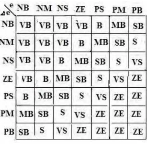
Because of these rules and some formulas, which change the gains automatically and continuously with the outputs, the controller becomes self tuning and can handle non-linear systems effectively. As far as stability is concerned, a fuzzy PI controller maintains the same stability as the conventional controller. It has two inputs Error(e) and change of error (∆e) and one output u. The membership functions for the inputs and output is shown in fig. where in which the domain is divided into 7 equal regions, denoted by NB(negative big), NM(negative medium), NS(negative small), ZE(zero), PS(positive small), PM(positive medium), PB(positive big).The shape of each membership function is triangular.
Fig. 4. Fuzzy rule
Similarly membership function for gain updating factor is obtained
Fig. 5. Membership function for Beta
The rule for gain updating factor is represented as If e is E and ∆e is ∆E then β is β.
The output scaling factor is modified by self tuning mechanism. The normalized values of error, change in error and output is given by
eN =Ne e, ∆eN=N∆e ∆e, and ∆u=(β Nu)∆uN (3)
Fig. 6. Fuzzy rule
5. Simulation Results and Discussions
To verify the proposed control method, digital simulation using MATLAB SIMULINK has been carried out. Simulation model is shown in Fig 7 and Simulink model of fuzzy logic based AC and DC voltage controllers are shown in Fig 8 & 9 respectively. The Fuzzy logic based self tuned PI controller is used to generate gate pulses for each leg of Voltage source converter of DSTATCOM.
,
Fig.9. Simulink model of fuzzy logic based DC voltage controller
\
The simulation is done firstly with unbalanced R-L load. The Fig 10. shows that the Fuzzy logic based controller is able to force the source to deliver the balanced currents by compensating reactive power.
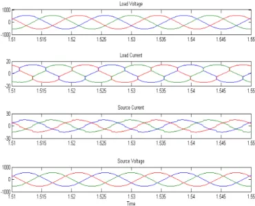
Fig. 11. Waveforms of Load Voltage, Nonlinear load current, balanced source current, source voltage with application of nonlinear load
The second simulation is done with nonlinear load. Non linear load is chosen using three phase bridge rectifier with resistive load. Fig 11 shows the waveforms of Load Voltage, Nonlinear load current, balanced source current, source voltage with application of nonlinear load. Now again the Fuzzy logic based controller is able to force the source to deliver the balanced currents by compensating reactive power so eliminating the harmonic current flowing in the source side thus decreasing the possibility of harmonic resonance occurred in the system especially a system with capacitor bank. Also, we can see in the same figures that the system settles faster. with the fuzzy logic controller. The simulation results prove the effectiveness of the proposed fuzzy logic controller of DSTATCOM.
6. Conclusion
This paper presents the design and simulation of fuzzy logic based DSTATCOM. The simulation is carried out for both linear and non-linear loads. The fuzzy controller is different from conventional controller as it attempts to implement the operator’s knowledge rather than mathematical equations of plant. The control engineer can design the fuzzy rule base for fuzzy controller and as well as fuzzy rule base for gain updating factor according to their knowledge. The proposed fuzzy based controller is proven to improve the performance of conventional controller. Matlab based simulation results have verified the effectiveness of the design methodology. It significantly enhances the power system stability. It is clear from the simulation results that to add a fuzzy controller for DSTATCOM is potential alternative to conventional controller.
References
[1] IEEE FACTS Application Task Force, “FACTS Applications”, Publication of IEEE PES SM, 1996.
[2] C. W. Edwards et. al., “Advanced static var generator employing GTO thyristors”, IEEE Trans. on Power Delivery, Vol. 3, No. 4, pp 1622-1627, Oct 1988
[3] Gyugyi, “Unified power-flow control concept for flexible AC transmission systems”, lEE Proceedings-C, Vol. 139, No. 4,pp. 323-331,July 1992.
[4] Gyugyi, “Dynamic compensation of AC transmission lines by solid-state synchronous voltage sources”, IEEE Trans. on Power [5] Delivery, Vol. 9, No. 2, pp. 904-911, April 1994.
[6] Hiyama ,T. Sameshima, “Fuzzy logic control scheme for on-line stabilization of multi machine power system”, Fuzzy Sets and [7] Systems, Vol. 39, pp. 181-194, 1991
[8] Li-Xin Wang, “A Course in Fuzzy Systems and Control”, Prentice Hall, 1997
DC Bus voltage 800V Switching Frequency 10kHz DC Bus Capacitor 8000 μF
.