Bhushan H. Patil
Int. Journal of Engineering Research and Applications
www.ijera.com
ISSN : 2248-9622, Vol. 4, Issue 8( Version 1), August 2014, pp.109-112
www.ijera.com 109 | P a g e
Parametric Study of Square Concrete Filled Steel Tube Columns
Subjected To Concentric Loading
Bhushan H. Patil
*, P. M. Mohite
***
(M. Tech (Structure) Student, Rajarambapu Institute of Technology, Rajaramnagar, Sakharale, Dist-Sangli (M. S.), India. 415414)
**
(Professor, Civil Department, Rajarambapu Institute of Technology, Rajaramnagar, Sakharale, Dist-Sangli (M. S.), India. 415414)
ABSTRACT
The Concrete Filled Steel Tube (CFST) member has many advantages compared with the conventional concrete structural member. This study presents on the behaviour of concrete-filled steel tube (CFST) columns under axial load by changing parameters. The parameters are thickness of steel tube, Grade of concrete and length of column. The study was conducted using ANSYS 13 finite element software. All the columns are 60 X 60 mm in size. The thickness of the tube is taken as 2, 3, 4, 5 and 6 mm for thickness variation. The grades of concrete infill are M25, M30, M40, M50, M60 and M70 used for grade variation. Lengths of columns are taken as 900, 1200, 1500, 1800, 2100, and 2400 mm for length variation. Buckling load is compared with Euro code 4 (1994).
Keywords
- Buckling, ANSYS, FEM, CFST.I.
INTRODUCTION
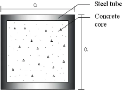
Now a day, the concrete filled steel tube (CFST) columns are widely used in construction. A concrete-filled tube (CFST) column consists of a steel tube filled with concrete as shown in fig 1. CFST columns are extensively used in structures involving very large applied moments, particularly in zones of high seismic risk. CFST have been used in frame structures as girder, beam and column. Composite column are structural members, which are mainly subjected to end moments and forces. The steel tube serves as a formwork for casting while the concrete reduces the construction cost. The tube act as a longitudinal and lateral reinforcement for the concrete core than no other reinforcement is needed. The steel tube enhances the core’s strength and ductility. The concrete core delays bending and buckling of the steel tube and steel tube prevents the concrete from spalling. CFST columns are suitable for tall buildings in high seismic regions since concrete delays the local buckling of steel hollow sections and increases the ductility of the section significantly. Composite columns are structural members, which are mainly subjected to axial compressive forces and end moments. The use of CFST columns provides large saving in cost by increasing the floor area by a reduction in the required size of column. This is very important in the design of tall buildings in cities where the cost of spaces are extremely high. In this paper, the five different models are created by using different thickness of steel tube (i.e. 2, 3, 4, 5, 6 mm) to study effect of increase in thickness of steel tube on behaviour of CFST column. The six different models are created by using different concrete cube strengths
(i.e. 25, 30, 35, 40, 50, 60 MPa) to study effect of grade of concrete on behavior of CFST column, also the six different models are created by using different column lengths (i.e. 900, 1200, 1500, 1800, 2100, 2400 mm) to study effect of length on behaviour of CFST column.
The Eigen value (linear) buckling analysis in ANSYS13 has been used to predict the ultimate loads and failure modes of circular CFST column. An Eigen value buckling analysis of a column will match the classical Euler’s solution. Buckling load was compared with Euler’s formula for composite column from euro code 4.
Fig. 1 SOLID45 Geometry in ANSYS
1.1 Euler’s formula for composite column
Euro code 4 (1994) is considered to provide the most logical approach for the design of composite columns. This design code basically adopts the steel approach to calculate the buckling load of a concentrically loaded column and modifies this to account for end moments by applying the reinforced concrete approach. Euler’s critical buckling load for concentrically loaded composite columns is given by Euro code 4.
Bhushan H. Patil
Int. Journal of Engineering Research and Applications
www.ijera.com
ISSN : 2248-9622, Vol. 4, Issue 8( Version 1), August 2014, pp.109-112
www.ijera.com 110 | P a g e Where,
(EI)e = EsIs + 0.8EcIc
(EI)e = effective elastic flexural stiffness. Is is the second moment of area of steel. Es is the elastic modulus of steel.
Ic is the second moment of area of concrete. Ec is the elastic modulus of concrete.
II.
MODEL DEVELOPMENT IN
ANSYS
For many engineering problems analytical solutions are not suitable because of the complexity of the boundary conditions, the material properties and the structure. The finite element method is the representation of a body or a structure by an assemblage of subdivisions. ANSYS is finite element based software which gives good results on analysis of any structural elements.
2.1 Element type
2.1.1) SOLID45 is used for modeling steel tube. It is used for the 3-D modeling of solid structures. The element has eight nodes and having three degrees of freedom at each node: translations in the x, y and z directions. The element has creep, plasticity, swelling, large deflection and large strain capabilities.
2.1.2) SOLID65 is used for modeling concrete core. It is used for the 3-D modeling of solids with or without reinforcing bars (rebar). This element is capable for cracking in tension and crushing in compression. The element is eight noded and having three degrees of freedom at each node: translations in the nodal x, y and z directions. The concrete is capable of crushing, cracking, creep and plastic deformation.
2.2 Model overview
The structural analysis program ANSYS is used to construct the FE model for CFST column. The SOLID 45 element was used for modelling of steel tube and SOLID 65 element was used for modelling of concrete core.
The bottom end is fixed. At bottom end displacement degrees of freedom in x, y, z directions (Ux, Uy, Uz) as well as rotational degrees of freedom in x, y, z directions are restrained to be zero. The top end is pinned. At top end rotational degrees of freedom are free and translation Uy is free remaining Ux, Uz are restrained.
Following properties are used for modelling CFST column.
Steel -Young’s Modulus, Es=200Gpa Poison’s ratio, νs=0.3
Density, ρs=7800kg/m3.
Concrete - Young’s Modulus, Ec=25000Mpa Poison’s ratio, νc=0.16
Density, ρc=2400kg/m3
An axial pressure of 1 unit was implemented over the top surface of the column.
III.
RESULT AND DISCUSSION
Fig. 2 Deflection of CFST column
Fig. 3 Stresses in CFST column
Eigen buckling analysis is carried out for the analysis of CFST column to find actual buckling capacity of the column. The deflected profile and stress profile of the CFST column is shown in Figure 2 and 3.
3.1 Thickness Variation
This study is conducted using the model on five rectangular CFST columns to investigate the effect of thickness variation on the performance of column. The load carrying capacities, deformation in CFST columns are studied.
Bhushan H. Patil
Int. Journal of Engineering Research and Applications
www.ijera.com
ISSN : 2248-9622, Vol. 4, Issue 8( Version 1), August 2014, pp.109-112
www.ijera.com 111 | P a g e Table 1. Thickness variation of steel tube
Thickness (mm)
Ansys Load (KN)
EC 4 load (KN)
Deflection (mm) 2 1689.516 1703.37 1.325 3 2133.334 2200.705 1.214 4 2532.463 2643.333 1.0248 5 2890.346 3043.687 1.0236 6 3210.44 3389.335 1.02261
The load carrying capacity of CFST column is increased with increase in thickness of steel tube as shown in table 1 and figure 4. Deformation is decreased with increase in thickness of steel tube as shown in table 1.
Fig. 4 Effect of Thickness variation of steel tube on loading capacity of CFST column
3.2 Concrete grade variation
This study is conducted using the model on seven rectangular CFST columns to investigate the effect of grade variation of concrete on the performances of CFST column. The load carrying capacities, deformation in CFST columns are studied.
All analyzed CFST columns are 60 X 60 mm in size, L equals to 900 mm and thickness of steel tube (T) equals to 2. The grade of concrete varies between M25 to M70 as shown in table 2.
Table 2. Grade Variation of Concrete
Grade
Ansys Load (KN)
EC4 Load (KN)
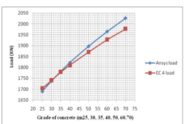
Deflection (mm) 25 1689.516 1703.37 1.00207 30 1737.399 1740.67 1.00122 35 1781.388 1777.971 1.00125 40 1822.298 1810.297 1.00129 50 1896.991 1869.977 1.0014 60 1964.455 1927.171 1.0004 70 2026.454 1976.904 1.00018
The load carrying capacity of CFST column is increased with increase in grade of concrete as shown in table 2 and figure 5. Deformation is decreased with increase in grade of concrete as shown in table 2.
Fig. 5 Effect of Grade variation of concrete on loading capacity of CFST column
3.3 Length variation of column
This study is conducted using the model on six circular CFST columns to investigate the effect of length variation of column on the performances of CFST column. The load carrying capacities, deformation in CFST columns are studied.
All analyzed CFST columns are 60 X 60 mm in size, thickness of steel tube (T) equals to 2 and length varies from 900, 1200, 1500, 1800, 2100, and 2400 mm. The grade of concrete used is M25.
Table 3. Length Variation of CFST column
Length (mm)
Ansys Load (KN)
EC 4 load (KN)
Deflection (mm)
900 1689.516 1703.37 1.002 1200 978.804 958.15 1.00 1500 635.328 613.21 0.92 1800 444.664 425.84 0.91 2100 328.255 312.86 0.88 2400 252.108 289.54 0.81
Fig. 6 Effect of length variation on loading capacity of CFST column
Bhushan H. Patil
Int. Journal of Engineering Research and Applications
www.ijera.com
ISSN : 2248-9622, Vol. 4, Issue 8( Version 1), August 2014, pp.109-112
www.ijera.com 112 | P a g e
IV.
CONCLUSIONS
Analytical studies are carried out by finite element method using ANSYS, The results are compared with Euro code 4 (1994) values and following inferences are drawn:
1. The results by ANSYS show good agreement with the euro code 4 (1994) Euler’s formula for composite.
2. When thickness of steel tube increased by 1 mm, capacity of CFST column is increased with 15 to 20 %.
3. Grade of concrete increased, capacity of CFST column is increased with 8 to 10 %.
4. Deformation decreases with increase in thickness of steel tube, grade of concrete and length of column.
5. When length of column increase by 300 mm, the load carrying capacity of CFST column decrease in range of 60 – 75 %.
REFERENCES
[1] Georgios Giakoumelis (2003), “Axial capacity of circular concrete-filled tube columns”, Journal of Constructional Steel
Research , vol 1, pp 1049–1068.
[2] Hsuan-Teh Hu (2005), “Finite element analysis of CFT columns subjected to an axial compressive force and bending
moment in combination”, Journal of
Constructional Steel Research, vol 1, pp 1692–1712.
[3] Jian Cai, Zhen-Qiang He (2006), “Axial load behavior of square CFT stub column with binding bars”, Journal of Constructional
Steel Research, vol 1, pp 472-483.
[4] Mohanad Mursi (),“Strength of slender concrete filled high strength steel box columns”, Journal of Constructional Steel
Research, vol 1, pp 1825–1848
[5] Mohamed Mahmoud El-Heweity (2012), “On the performance of circular
concrete-filled high strength steel columns under
axial loading”, Alexandria Engineering
Journal, vol 1, pp 109-119.
[6] N.E. Shanmugam, B. Lakshmi (2001), “State of the art report on steel–concrete
composite columns”, Journal of
Constructional Steel Research, vol 1, pp 1041–1080.
[7] Raghu K.S, E. Ramesh Babu (2013), “Buckling behavior of concrete filled steel
tube under finite element method”,
International Journal of Emerging Trends in Engineering and Development, vol 4, pp 145-161.
[8] Shosuke Morino , Keigo Tsuda (2011),
“Design and Construction of
Concrete-Filled Steel Tube Column System in Japan”,
Earthquake Engineering and Engineering Seismology, vol 4, pp 51-73.
[9] Wei-bin Yuan, Jun-jie Yang (2013), “Experimental and numerical studies of short concrete-filled double skin composite tube columns under axially compressive loads”, Journal of Constructional Steel