Angra dos Reis Reactor Neutrino Oscillation Experiment
J. C. Anjos1, A. F. Barbosa1, A. Bernstein2, N. S. Bowden3, W. Fulgione4, E. Kemp5, J. Magnin1, H. Nunokawa6, O. L. G. Peres5, D. Reyna7, A. Schilithz1, R. C. Shellard1,6, and and R. Zukanovich Funchal8
(1)Centro Brasileiro de Pesquisas F´ısicas, Rua Dr. Xavier Sigaud 150, Rio de Janeiro, RJ, 22290-180, Brazil (2)Lawrence Livermore National Laboratory, 7000 East Ave, Livermore, CA 94551, USA
(3)Sandia National Laboratories, 7011 East Ave, Livermore, CA 94550, USA
(4)Istituto Nazionale di Astrofisica - Istituto di Fisica dello Spazio Interplanetario, Corso Fiume 4, 10100, Torino, Italy (5)Instituto de F´ısica Gleb Wataghin, Universidade Estadual de Campinas,
Caixa Postal 6165, Campinas, SP, 13083-970, Brazil
(6)Departamento de F´ısica, Pontif´ıcia Universidade Cat´olica do Rio de Janeiro, Caixa Postal 38071, Rio de Janeiro, RJ, 22452-970, Brazil
(7)Argonne National Laboratory, 9700 S. Cass Avenue, Argonne, IL, 60439, USA and (8)Instituto de F´ısica, Universidade de S˜ao Paulo, Caixa Postal 66318 S˜ao Paulo, SP, 05315-970, Brazil
Received on 10 August, 2006
We present the status and plans of the Angra Project, a new reactor neutrino oscillation experiment, proposed to be built in Brazil at the Angra dos Reis nuclear complex. This experiment is aimed to measureθ13, the last unknown of the three neutrino mixing angles. We propose a high sensitivity multi-detector experiment, able to reach a sensitivity to antineutrino disappearance down to sin22θ13=0.006 in a three years running period, by combining a high luminosity design, very low background from cosmic rays and careful control of systematic errors. We also intend to explore the possibility to use the neutrino detector for purposes of safeguards and non-proliferation of nuclear weapons.
Keywords: Reactor Neutrinos; Neutrino Oscillations; Neutrino Mixing Angle; Safeguards and Non-Proliferation
I. INTRODUCTION
Nuclear reactors played a very important role in neutrino physics. Indeed, neutrinos were first experimentally detected 50 years ago by Reines and Cowan [1] using the outcoming ¯νe
flux from a nuclear reactor and observing neutrino interactions through the inverse-βdecay,
¯
νe+p→e++n. (1)
Recently, the KamLAND experiment [2], also using neu-trinos produced in nuclear reactors, observed clear signals of neutrino oscillation, establishing the Mikheyev-Smirnov-Wolfenstein (MSW) [3] large mixing angle solution for the solar neutrino problem.
Despite the fact that enormous progress has been made in neutrino physics in the last decade [4], there are still three unknown parameters necessary to fully describe the neutrino oscillation phenomena: the mixing angleθ13, the CP phaseδ and the sign of the mass squared difference,∆m213≡m23−m21, which is positive (negative) if the mass hierarchy is normal (inverted).
There is a general consensus that the measurement ofθ13is the most important step towards further progress in the field. In fact,θ13controls the experimental accessibility of the other two unknown parameters. If θ13 is non-zero and relatively large, it can open the possibility to measureδby the observa-tion of CP violaobserva-tion in the leptonic sector and to determine the neutrino mass hierarchy.
While it is true thatθ13can also be measured in accelerator based appearance experiments, such measurements are sub-ject todegeneracies [5] due to specific combinations of the
unknown oscillation parameters. On the other hand, reactor neutrino short baseline experiments can provide a very clean measurement ofθ13 [6], free of ambiguities from degenera-cies and matter effects [3]. Moreover, by combining the reac-tor measurement ofθ13and accelerator based oscillation ex-periments, the determination of the other mixing parameters become significantly improved [7].
In this contribution we describe the main features of the Angra Experiment [8], a project to observe antineutrino dis-appearance at the Angra dos Reis nuclear complex in Brazil. The experimental approach is to measure, with high precision, the neutrino energy spectra at two different distances from the reactor core: one of them obtained by a close detector (here-after called the Near Detector - ND) located at∼300 m from the reactor, providing us with the reference spectrum mini-mally affected by oscillations; and the other one obtained by a detector placed at a suitable distance, typically∼1.5 km (the Far Detector - FD), to observe the spectral distortion induced by oscillations. Thus, the neutrino mixing parameter values can be inferred by the differences between the ND and FD spectral shapes.
The Brazilian nuclear reactors are located at Angra dos Reis, a city about 150 km south of Rio de Janeiro. The Angra nuclear reactor complex has two operational reactors (Angra I and II) and a third one under approval process (Angra III, similar to Angra II). The state owned company Eletronuclear is responsible for the general management and commercial operation of the plant. The thermal power of the reactors are 2 GW and 4 GW for Angra I and II, with uptimes around 83% and 90%, respectively. The topology of the surrounding ter-rain, formed by mountainous granite, is an advantage of the site.
FIG. 1: Map of the Angra site, where the positions of the reactor, VND, ND and FD are indicated. The solid line indicates the hori-zontal tunnel to be excavated to give access to the far detector ex-perimental hall, under the Morro do Frade peak. The solid circles indicate the distance from the Angra II reactor in 500 m steps.
We show in Fig. 1 a topographic map of the reactor complex where the positions of the three detectors are indicated. At about 1.5 km from the Angra II reactor, there is the so-called “Morro do Frade”, the highest nearby peak (700 m), providing an overburden of∼2000 m.w.e. .
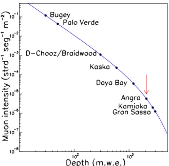
In Fig. 2 we present the expected muon flux as a function of the depth. As can be seen, the Angra FD site has overburden comparable to dedicated underground facilities. Thus, a sub-stantial reduction of the cosmic ray induced background can be achieved by construction of an underground experimental hall, accessible by a horizontal tunnel to be built at a much lower cost than vertical shafts.
III. OSCILLATION PROBABILITY
Neglecting terms that will give very small contributions, the antineutrino survival probability, P(¯νe→ν¯e), in vacuum is
described by
FIG. 2: The solid curves gives the underground muon flux extrapo-lated from the LVD experiment results [9]. Big dots indicate overbur-dens of different reactor experiments. The arrow points to the Angra FD situation. The two deepest installations, added for comparison purpose, are dedicated underground laboratories (Kamioka in Japan and Gran Sasso in Italy).
P(¯νe→ν¯e) ≈ 1−sin22θ13sin2
∆m2 13L 4E
−cos4θ13sin22θ12sin2
∆m212L 4E
, (2)
whereLis the propagation distance (the baseline).
Taking into account the typical energies for reactor neutri-nos (E∼3-5 MeV), the first minimum of the probability,i.e., the point of maximal flavour conversion, can be achieved at L∼1.5 km, coinciding with the proposed far detector base-line.
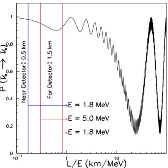
We show in Fig. 3 a plot of the probability as a function of L/E, where relevant limits for the Angra case are indicated by the vertical lines. Here the probability was computed assum-ing sin22θ13=0.05, and using the best fit values of the mix-ing parameters from solar, atmospheric, reactor and accelera-tor neutrino measurements,∆m212=8×10⁻⁵eV2, sin2θ
12= 0.31,∆m213=2.5×10⁻³eV2, sin22θ23=1.0 [2, 10–13].
FIG. 3: Antineutrino survival probabilityP(ν¯e→ν¯e)as function of the ratioL/E[km/MeV]. Vertical lines indicate some relevant reactor neutrino energies. E=1.8 MeV corresponds to the reaction thresh-old. The peak of the energy spectrum weighted by the detection cross section in the absence of oscillation is atE∼4 MeV, and the contri-bution of neutrinos with energy <∼ 5 MeV is the most important.
IV. THE EXPERIMENTAL DESIGN
The Angra neutrino oscillation experiment will consist of two neutrino detectors to be set at the near/far configuration, as explained above. The third one, the VND, is planned to be built as a prototype. In addition, the very near detector will work as a non-intrusive nuclear reactor monitor, within the international effort promoted by the IAEA, to develop tools for verification of safeguards and non-proliferation of nuclear weapons. The VND (1 ton), ND (50 ton) and FD (500 ton) will have a very similar design, scaled appropriately, as shown in Fig. 4. The design concept is based on two complementary systems: theantineutrino detectorand themuon veto, briefly described in the following sections.
A. The antineutrino detector
The antineutrino detector, designed in a standard mono-lithic configuration is made of three concentric volumes with different functionalities: i) the ¯νetarget - innermost volume
filled with gadolinium doped liquid scintillator with high ef-ficiency to tag inverse-βdecay events due to the high cross section for neutron capture; ii) the gamma catcher - interme-diate volume filled with standard scintillator to increase the detection volume for gammas from neutron capture and, as a consequence, the fiducial volume of the target; iii) the non-scintillating buffer - the outermost volume filled with mineral oil to reduce the radioactivity from outside.
FIG. 4: Schematic view of the detector showing all subsystems, de-scribed in detailed in the text. A) Target ; B) Gamma-Catcher ; C) Buffer ; D) Vertical tile of veto system. Some tiles of the frontal part were omitted just to show the antineutrino detection system. E) X-Y horizontal paddles of the Veto system. They are placed above and under the external cylinder of the buffer, for muon tracking through the detector. The top X-Y system in the drawing is shifted upward for viewing purposes. The dashed area shows its true position.
The phototubes are installed in the buffer outer wall, with about 15% of surface coverage, looking inside to monitor light pulses from interactions. The organic liquid scintillator is a solvent mixture with a basic component like CnH2n+2,<n> = 9.8, and additional activators and wavelength shifters such as PPO and POPOP. The proton richness of this kind of com-pound provides a large number of target particles for the main antineutrino interaction channel, the inverseβ-decay (Eq. (1)). All three volumes are filled with the same liquid basis to guar-antee their optical match and uniformity of light collection by the phototubes.
The ¯νesignature is given by the detection in time
coinci-dence of the secondary particles: e+,n. The positron gener-ates the prompt signal and the delayed detection of gammas from neutron capture gives the second signal. The gamma de-tection must occur in an adjustable time window with typical duration of 3τ<∆t<5τ, whereτis the mean time interval for neutron capture. Noise rejection can be considerably im-proved by reducing the time window for coincident pulses. The neutron capture cross section is increased by a factor up to 105by loading the scintillator with gadolinium in a concen-tration of 0.1−0.5%, resulting in 15µs<τ<50µs, a factor ∼5 shorter than the mean time interval for capture on free protons in unloaded scintillators [14].
B. The muon veto
The muon veto is an external layer, consisting of plastic scintillator paddles, screening the internal systems (the anti-neutrino detector). All paddles have attached phototubes at both ends and work in fast time coincidence, triggered by muons from cosmic rays passing through the apparatus.
The muons can produce neutrons by spallation either in the detector or in surrounding material. These background neu-trons can be captured in the scintillator, producing gammas in delayed coincidence with the muon signal or any other spuri-ous signal. This kind of events can mimic a true anti-neutrino interaction. So, after a trigger coming from the muon veto sys-tem, the readout of the front-end electronics is suppressed in case of an instantaneous recognition of a muon induced event, or otherwise, just flagged to enable an accurate analysis of the background.
Substantial improvement in noise rejection can be achieved with a suitable overburden condition, as planned for the ND and FD experimental rooms. The VND is planned to be in-stalled at least some tens of meters underground, and with an extra shielding, provided by thick walls of some dense mater-ial (iron or concrete, for instance).
V. EXPERIMENTAL REACH
In Table I, we show preliminary estimations of the signal and background rates per day, assuming target masses of 1 ton, 50 ton and 500 ton for VND (L=50 m), ND (L=300 m), and FD (L=1500 m), respectively.
Detector Very Near Near Far
Signal 1800 2500 1000
Muons (Hz) 150 ∼30 0.3
9Li bkg 44 ≤20 ∼2
TABLE I: Expected rates per day for the Angra Experiment. Signal and9Li background (correlated noise) are in events/day units. Cal-culations were done assuming target masses as follows: 1 ton VND (L=50 m), 50 ton ND (L=300 m) and 500 ton FD (L=1500 m).
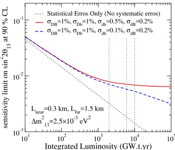
Based on the yields at the ND and FD, the expected sensi-tivity on sin22θ13 at 90% CL as a function of the integrated luminosity is shown in Fig. 5. The assumed value of∆m213is 2.5×10⁻³eV2. The calculations were performed by mini-mizing theχ2function built to take into account four different types of systematic errors,σi j, whose assumed values are
in-dicated in the figure. We used the sameχ2function used in [15]. The subscripts D(d) represents errors correlated related) between detectors and B(b) errors correlated (uncor-related) between bins of the measured energy spectra. As can be seen a limit of sin22θ13=0.006 at 90% confidence level can be achievable within three years provided that systematic errors are well controlled.
101 102 103 104 105
Integrated Luminosity (GW.t.yr)
10-3 10-2
sensitivity limit on sin
2 2 θ 13
at 90 % CL
DB Db db dB
∆m213=2.5×10⁻³ eV2
Lnear=0.3 km, Lfar=1.5 km
FIG. 5: Sensitivity limit as a function of the integrated luminosity. Vertical dashed lines represent 1, 3 and 5 years of data taking.
10-3 10-2 10-1
sin
22
θ
1310-4 10-3 10-2 10-1
∆
m
2 13
(eV
2 )
σDB=1.0%,σDb=1.0%,σdb=0.5%,σdB=0.2% σDB=1.0%,σ
Db=1.0%,σdb=0.1%,σdB=0.2%
No Systematic Errors
Expected Sensitivity at 90% for 6000 GW.t.yr
Lnear=0.3km, Lfar=1.5km V
near/Vfar=0.1
FIG. 6: 90% CL sensitivity curve in the parameter space of∆m213 and sin22θ13for 3 years of data taking assuming the same systematic errors as in Fig. 5. The blue band indicates the allowed range of∆m213 coming from atmospheric neutrino observation [11].
In Fig. 6 we show the expected sensitivity in the parameter space of∆m2
13and sin22θ13for 3 years of data taking assum-ing the same systematic errors as in Fig. 5.
VI. THE VERY NEAR DETECTOR
Energy (MeV)
2 4 6 8 10 12
Nb neutrino/fission
-6 10
-5 10
-4 10
-3 10
-2 10
-1 10
1
235U
239Pu
241Pu
238U
Neutrino fluxes from main fuel components
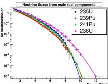
FIG. 7: Measured spectra of antineutrinos from the main components of the nuclear fuel. Taken from Ref. [20].
VND will also be used to monitor the reactor activity, and to provide an additional tool for verification of safeguards and non-proliferation of nuclear weapons.
In fact, the number of antineutrinos detected,nν, is related to the reactor thermal power,W, by the relationship
nν=γ
W NH
R2 , (3)
whereNHis the number of hydrogen atoms in the fiducial
vol-ume,Ris the distance from the source to the detection point andγis a constant which takes into account the contributions to the power output made by the fissile isotopes235U,238U, 239Pu and241Pu [16].
Recent studies have shown the feasibility of using the anti-neutrino emission from nuclear reactors as an on-line monitor of the reactor activity. A prototype of this kind of detector is running at the San Onofre reactor (U.S.A.) [17], and a previ-ous experiment was done at the Rovno reactor (Ukraine) [16]. Recent theoretical work shows also that a detector capa-ble of measuring the antineutrino spectrum with high preci-sion can determine not only the thermal power of the reactor but also the fractions of isotopes in the fuel. It is possible to
achieve an accuracy of a few percent without knowing the ini-tial fuel compositions [18] because the neutrino energy spec-trum from each of the different isotopes is different, as shown in Fig. 7 [19].
In a joint survey of the Angra site with engineers from the Eletronuclear company a preliminary location at 66 m from the reactor core has been selected for the position of the Very Near Detector. At this distance we expect about 1,000 events/day for a 1 ton detector.
VII. SUMMARY
We have presented the status and plans of the neutrino os-cillation experiment to be performed at the Angra dos Reis nu-clear complex in Brazil. This experiment proposes to reach a sensitivity to anti-neutrino disappearance down to sin22θ13∼ 0.006 by measuring the spectrum distortion caused by the os-cillation.
As a first step, we are developing a small prototype detector close to the reactor core (L≃60−70 m), the very near detec-tor, which will also be used to monitor the reactor activity, and to provide an additional tool for verification of safeguards and non-proliferation of nuclear weapons. We are currently per-forming Monte Carlo simulations to achieve the best detector design and studying solutions to the front-end electronics and data acquisition systems.
We intend to start experimental activities in the Angra site at the end of 2006, measuring the local muon flux, and in-stalling communication systems for remote control and data transfer. The planned turn-on dates are 2008 for the Very Near Detector and 2013 for the complete Angra configuration.
Acknowledgments
This project is sponsored by the LAMPADIA Foundation, Fundac¸˜ao de Amparo `a Pesquisa do Estado de Rio de Janeiro (FAPERJ), Fundac¸˜ao de Amparo `a Pesquisa do Estado de S˜ao Paulo (FAPESP), and Conselho Nacional de Desenvolvimento Cient´ıfico e Tecnolgico (CNPq).
[1] F. Reines and C. L. Cowan, Nature,178, 446 (1956); Phys. Rev.92, 830 (1953);ibid.113, 273 (1959); C. L. Cowanet al., Science124, 103 (1956).
[2] K. Eguchiet al.[KamLAND Collaboration], Phys. Rev. Lett. 90, 021802 (2003); T. Arakiet al.[KamLAND Collaboration], Phys. Rev. Lett.94, 081801 (2005).
[3] L. Wolfenstein, Phys. Rev. D17, 2369 (1978); S. P. Mikheyev and A. Yu. Smirnov, Yad. Fiz.42, 1441 (1985) [ Sov. J. Nucl. Phys.42, 913 (1985)]; Nuovo Cim. C9, 17 (1986).
[4] M. C. Gonzalez-Garcia and Y. Nir, Rev. Mod. Phys.75, 345 (2003); S. Pakvasa and J. W. F. Valle, Proc. Indian Natl. Sci. Acad. 70A, 189 (2004); R. N. Mohapatra et al., arXiv:hep-ph/0510213.
[5] J. Burguet-Castellet al., Nucl. Phys. B608, 301 (2001); H. Mi-nakata and H. Nunokawa, JHEP0110, 001 (2001); G. Fogli and E. Lisi, Phys. Rev. D54, 3667 (1996); V. Barger, D. Marfatia and K. Whisnant, Phys. Rev. D65, 073023 (2002).
[6] K. Anderson et al., arXiv:hep-ex/0402041 (also available at http://www.hep.anl.gov/minos/reactor13/white.html ); See also talks at Fourth Workshop on Future Low En-ergy Experiments, Hotel do Frade, Angra dos Reis (RJ), Brazil, Feb. 23-25 2005. Talks available at http://www.ifi.unicamp.br/˜lenews05/
[10] B. Aharmim et al. [SNO Collaboration], Phys. Rev. C 72, 055502 (2005).
[11] Y. Fukudaet al.[Super-Kamiokande Collaboration], Phys. Rev. Lett.81, 1562 (1998).
[12] M. H. Ahn et al. [K2K Collaboration], Phys. Rev. Lett.90, 041801 (2003).
[13] D. G. Michael et al. [MINOS Collaboration], arXiv:hep-ex/0607088.
[14] E. Kemp, PhD thesis, State University at Campinas -
UNI-[17] A. Bernstein, Y. F. Wang, G. Gratta and T. West, J. Appl. Phys. 914762, (2002) [arXiv:nucl-ex/0108001].
[18] P. Huber and T. Schwetz, Phys. Rev. D70, 053011 (2004). [19] K. Schreckenbach et al., Phys. Lett. B 160, 325 (1985);
A. A. Hahnet al., Phys. Lett. B218, 365 (1989).