Effect of the Fiber Reinforcement on the Low Energy Impact Behavior of …
J. of the Braz. Soc. of Mech. Sci. & Eng. Copyright 2003 by ABCM October-December 2003, Vol. XXV, No. 4 / 325
W. A. de Morais and
J. R. M. d’Almeida
Materials Science and Metallurgy Department Pontifícia Universidade Católica do Rio de Janeiro Rua Marquês de São Vicente, 225 22453-900 Rio de Janeiro, RJ. Brazil [email protected]L. B. Godefroid
Metallurgical Engineering and MaterialsDepartment Universidade Federal de Ouro Preto Campus Universitário Morro do Cruzeiro, s/n 35400-000 Ouro Preto, MG. Brazil
Effect of the Fiber Reinforcement on
the Low Energy Impact Behavior of
Fabric Reinforced Resin Matrix
Composite Materials
The influence of the fiber used as reinforcement in resin matrix composite materials submitted to repeated low energy impacts is analyzed. The aramid, glass and carbon fiber composites were submitted to drop weight tests from 0.5m and from 1m. The number of impact events necessary to cause failure was recorded, and the fracture characteristics of each composite were analyzed by optical microscopy and X-rays radiography. The results obtained showed that carbon fiber composites have better performance than the glass and aramid composites. This behavior was partially attributed to the higher elastic energy absorption of carbon fibers that delays the propagation of delamination, and fiber breakage. The failure mode of glass fiber composites was dominated by the higher number of glass fibers per surface area of the composites. The worst behavior shown by aramid composites was attributed to the intrinsic anisotropy of aramid fibers.
Keywords: Low energy impact, polymer matrix composites, microstructural characterization, composite performance
Introduction
Like parts or structures assembled from the common isotropic engineering materials, fiber reinforced resin matrix composite structures can be subjected to impact loading during their designed life. Fiber composites have, nevertheless, a unique interaction with the externally applied load, since severe internal damage can be generated without any external sign. In fact, several damage mechanisms can be operative, viz. matrix cracking, fiber breakage, fiber-matrix interface rupture and delamination (Bibo and Hogg, 1996; Zhou, 1998). The challenge for a designer is to establish the safe boundaries where a composite part or structure can be used after an impact that do not cause rupture on a single event. Such non-destructive impact events usually occur when low energy impacts are involved, the impact velocity varying on the range of 1 to 10 m/s (Zhou, 1995). For this range of impact velocities many parameters could be involved on the composite response like the mass of indenter, impact geometry, laminate stacking sequence and fiber type, among others (Zhou, 1995; Wen, 2001; Christoforou, 2001). Although several works have already been done on different topics about low energy impact and the response of composite structures, many aspects are not fully understood and a unified approach has yet to be postulated.1
In this paper the endurance to repeated low energy impact events is evaluated as a function of the fiber reinforcements used. The macroscopic aspects of the damage generated were identified and were correlated to the microstructural characteristics of the composites.
Experimental Materials and Procedures
In order to vary the stiffness of the composites while maintaining a constant volume fraction of fibers, three different epoxy matrix composites were manufactured using carbon, glass and aramid fibers as reinforcements, respectively. The composites were vacuum bagged and autoclaved using proprietary curing schedules. Details of these cure schedules are given elsewhere (Morais, 1999). This procedure allows the manufacture of laminates
Paper accepted October, 2003. Technical Editor: Atila P. Silva Freire.
with very uniform thickness, low void content and high volume fraction of fibers. Square plates with an area of 21 x 21 cm2 were
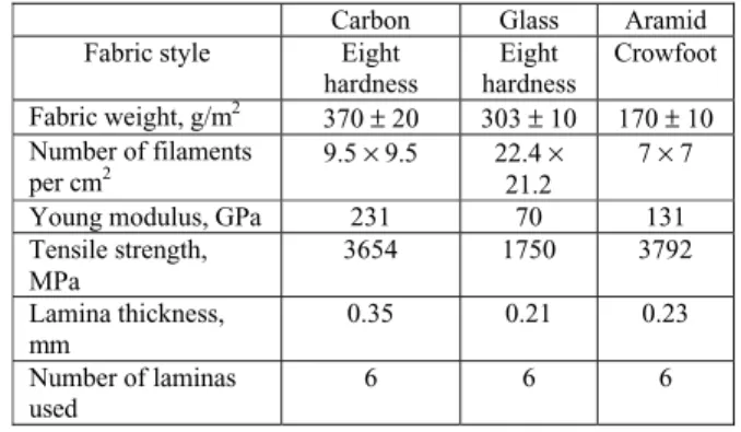
obtained. All laminates were fabricated with the same number of plies and with 0-90o fabrics. Details of the reinforcements used are shown in Table 1.
Table 1. Data sheet of the fiber reinforcements and pre-preg laminae.
Carbon Glass Aramid Fabric style Eight
hardness
Eight hardness
Crowfoot Fabric weight, g/m2
370± 20 303± 10 170± 10 Number of filaments
per cm2 9.5× 9.5 22.4×
21.2
7× 7 Young modulus, GPa 231 70 131 Tensile strength,
MPa
3654 1750 3792 Lamina thickness,
mm
0.35 0.21 0.23 Number of laminas
used
6 6 6
W. A. de Morais et al
/ Vol. XXV, No. 4, October-December 2003 ABCM
326
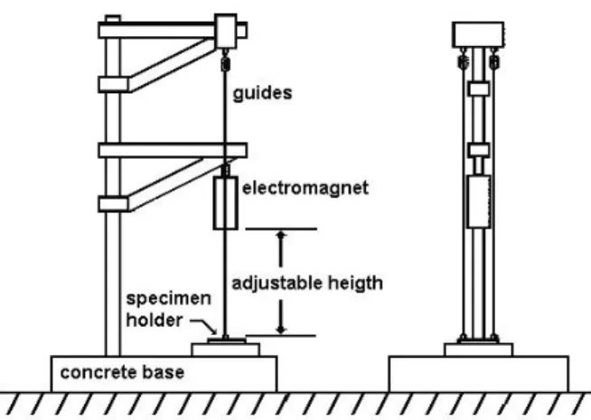
Figure 1. Experimental set-up of the drop-weight test apparatus.
The microstructure of the fabricated composites was analyzed by optical microscopy and scanning electron microscopy to observe the existence of voids and determine the distribution of the fibers. X-rays radiography and visual inspection were used to observe the macroscopic damages introduced by the repeated low energy impacts. The X-rays analysis was done using an instrument with 160 kV of maximum capacity. The composites were exposed to X-rays beans of 80 kV, during 3 minutes. The beam current used was 3 mA, and the plates were placed at a distance of 75 cm from the beam. The film was placed directly onto the rear face of the exposed plates, what essentially does not alter the source to specimen to film distance.
Experimental Results and Discussion
The micrographic analysis shows that the composites obtained have a low volume fraction of voids (Vv < 2%) and a high volume
fraction of fibers (Vf ranging from 50 to 65%). These figures were
obtained by digital image analysis processing, and the whole procedure used is described in another work (Paciornik et al., 2002). Figure 2 shows typical micrographic aspects observed for all composites. In Fig. 2a an overall view of the aramid reinforced composites is shown. One can see a regular spacing of the fibers tows, although some resin rich areas are present. Some fairly large voids could also be seen at the warp to fill intersection, as indicated (→). Although rare, these were the largest voids observed at the microstructure of these composites. Figure 2b is a closest view of the typical microstructure of the composites used in this work. One can see the distribution of fibers inside a tow of the carbon reinforced composites. No voids are observed and the fibers are randomly distributed.
The micrographic analysis shows that the main features observed in the microstructure of the composites were mainly very similar and, therefore, enable a direct comparison of the results obtained on the mechanical tests, because the fiber distribution, void content and distribution of resin rich areas were similar for every composite used in this work. The similarities of the microstructural aspects were particularly true in respect to the volume fraction of fiber and fiber spatial distribution, which are two of the main structural features that govern the mechanical behavior of a composite (Matthews and Rawlings, 1994). One has, nevertheless, to observe that the fibers´ diameter is not constant. From the data in Table 1, and from the micrographic analysis performed, it follows that the average diameter of the fibers was 8 µm, 12 µm and 24 µm for the glass, carbon and aramid fibers, respectively. Therefore, for a constant volume fraction of fibers, the distance between the fibers
varies, being shorter for the smaller fibers (Lange and Radford, 1971). This aspect could be very important, because more fibers will exist on a given area the smaller the diameter of the fiber is and, thus, the interface area will be maximized, leading to a better stress distribution on the composite. This shall delay the initiation of defects such as matrix cracking, fibers breakage and/or interface rupture.
Figure 2. (a) Overall aspect of the microstructure of the composites, showing a regular fiber spacing and low void content; (b) Detail of the fiber distribution inside a tow.
Effect of the Fiber Reinforcement on the Low Energy Impact Behavior of …
J. of the Braz. Soc. of Mech. Sci. & Eng. Copyright 2003 by ABCM October-December 2003, Vol. XXV, No. 4 / 327
# 1 # 3
# 6
# 1 # 3 # 6 # 8 # 8
On the other hand, the damage suffered by the glass fiber composite was different. As shown in Fig. 3c, one can see that both at the front and rear sides the dome failure prevails. This homogeneous failure, with fiber and matrix crushing in the contact zone, is characteristic of local damage (Christoforou, 2001). This failure mode can be attributed to the higher number of fibers by surface area due to the lower diameter of the glass fibers, as highlighted earlier.
COMPOSITE FRACTOGRAPHICASPECT (DROP HEIGTH
= 1 M)
FRONT REAR
(a) Carbon
(b) Aramid
(c) Glass
Figure 3. Fractographic aspects of the composites.
Table 2 shows the maximum number of impacts that caused failure on the composites. One can see that the carbon fiber reinforced composite has an outstanding performance when compared to the glass and aramid fiber composites.
COMPOSITE X-RAYS RADIOGRAPH
Carbon Fiber
Figure 4. Radiograph aspect of the rear side of the laminate.
Table 2. Experimental results of the repeated impact tests.
Maximum number of impacts to failure
from
Maximum load (N) at the first hit from Composite
0.5 m 1 m 0.5 m 1 m Aramid fiber 7 2 1125 1120 Glass fiber 58 4 2000 1375 Carbon fiber > 1500 12 3000 1900
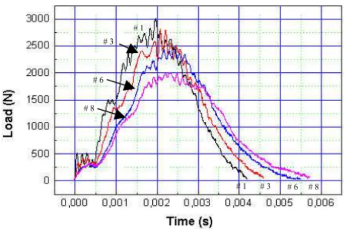
A typical load vs. time curve obtained for the carbon fiber composite as a function of the number of the repeated impact events is shown in Fig. 5. It can be seen that, as the number of impact increases the maximum load sustained by the composite decreases and the time duration of the impact event increases. It can also be seen that the amplitude of the oscillations in each curve decreases with the increase of the number of impacts. These aspects were common to all composites tested and reflect the interaction of the composites´ microstructure, and the geometry of the test specimen and clamping device, with the incident indenter.
Oscillations on the load signal are correlated with the interaction of the elastic wave generated at the moment of the impact with the indenter (Ambur and Starnes,Jr, 1995; Wu and Springer, 1988; Meyers, 1994). The wave generated propagates from the impact point, reflects at the clamped edges and then returns back to the initial point were it interacts with the indenter. The presence of oscillations on the load signal is, therefore, a common aspect found on load vs. time impact curves for composites as well as for isotropic materials (Adams et al., 1990). The higher amplitude of the peaks at the trace of the first impact curve reflects the propagation of the elastic wave on a more homogeneous, defect-free, medium. The attenuation of the oscillations with the increase of the number of impacts is due to scattering phenomena of the elastic waves, such as wave reflection at newly created interfaces inside the material and wave interactions (Meyers, 1994). The evaluation of the evolution of the damage on the composites could then be qualitatively characterized by the reduction on the oscillation of the load signal as a function of the increase of the number of impacts.
Figure 5. Typical load vs. time curve obtained for the three types of composites tested. Observe the attenuation of the oscillations on the load signal with the increase of the number of impacts.
Figure 5 also shows another qualitative information about the damage evolution on the composite due to the repeated impact events. As one can see, the duration of each impact event increases as the number of impacts increases. The traces of the curves sketched in Fig. 5 represent, from left to right, the 1st, 3rd, 6th and 8th
W. A. de Morais et al
/ Vol. XXV, No. 4, October-December 2003 ABCM
328
impact produces new defects and contributes to the propagation of the existing ones, each time a more damaged and less stiff structure is being tested. Therefore, the displacement of the indenter, u, increases, sinceu∝k1/(k1+k2) wherek1andk2are, respectively, the
contact stiffness between the composite – indenter pair and the specimens´ stiffness (Williams and Adams, 1987). As the timet is proportional to u (t∝u),t must increase, as observed.
The value of the maximum load, Fmax, attained by each
composite at the first hit is also shown in Table 2. These values reflect the initial resistance of the composites to the impact event, as shown by the mathematical modeling of the variation ofFmax with
the number of impacts (Morais, Godefroid and d’Almeida, 2002a; Morais, Godefroid and d’Almeida, 2002b). Therefore, and in accordance with the results of the maximum numbers of impacts withstand before failure, Table 2, one can see that the carbon fiber composite has the better performance, and the aramid composite has the worst.
The results observed can be correlated with the mechanical properties of the fibers and their global response to the applied load, since the number of plies and the volume fraction of fibers were kept constant. For the carbon and glass fiber reinforced composites the results follow directly from the properties of the fibers, Table 1. The stiffer and more resistant carbon fiber will support and redistribute better the applied load, postponing the propagation of defects. For the impact events from 0.5 m, where before matrix crushing under the point of impact the event can be tough as almost elastic, the far higher resilience of the carbon composites is responsible for its “infinite” life, when compared to the glass composite behavior.
For the aramid composites one has to note the boundary conditions used during the tests. Aramid fiber composites are recognized as one of the best materials against ballistic impact, were wave propagation governs the whole impact event. Under the low energy impact conditions used in this work, continuum mechanics is still valid, whereas mechanical resonance in the test specimen and test machine is important (Meyers, 1994). This highlights the anisotropy of aramid fibers (Morgan and Allred, 1989), since fiber failure under impact involves the shear strength, S12, of the fiber
(Hou et al., 2000). For aramid fibers this is a drawback because of its low shear strength when compared to its tensile strength. In fact, the interlaminar shear strength of aramid composites is much lower than the values measured for glass or carbon fiber composites (Morgan and Allred, 1989). Therefore, the aramid composites have lower endurance against the repeated shock of small energy objects, since fiber failure and the onset of gross delamination occur easier. Extensive peeling of the aramid fibers, denoting their low shear strength, was observed for aramid composites tested under high energy Charpy impact tests (Naglis and d’Almeida, 1998).
Conclusions
The performance against low energy repeated impact events of the composites tested were dominated by the intrinsic characteristics of the fiber reinforcements.
Carbon composites showed the best performance due to the higher elastic energy absorption capacity of carbon fibers. Therefore, the deformation energy given to the composite by the falling weight was efficiently redistributed, delaying the initiation and propagation of defects. The endurance of these composites was, thus, much higher than those from the more compliant glass or aramid fiber composites.
As the volume fraction of the composites was kept constant, the smaller diameter of the glass fibers used in this work had an
outstanding influence on the behavior of glass fiber composites. The higher number of fibers per unit area, resulting from the smaller distance between them, and the correlated maximization of the interfacial area, promotes an efficient way to absorb impact energy. The dome like failure mode associated to these composites is, in fact, indicative of matrix crushing, not to delamination. This aspect shows that an homogeneous and localized failure mode is operative.
The performance of aramid composites was dominated by the anisotropic behavior of the aramid fibers. The failure of the composites was dominated by the low shear strength of these fibers. Therefore, matrix and fiber crushing under the point of impact was rapidly followed by delamination and collapse of the composites after few impact events.
Acknowledgements
The authors acknowledge the Brazilian Agency CNPq for the grants to W.A. de Morais.
References:
Adams GC, Bender RG, Crouch BA, Williams JG, 1990, “Impact fracture toughness tests on polymers”, Polym.Eng.& Sci., Vol.30,pp.241-248.
Ambur DR, Starnes,Jr JH., 1995, “Low speed impact damage initiation characteristics of selected laminated composite plates”, J.of American Institute of Aeronautics and Astronautics, Vol.33, pp.1919-1925.
Bibo GA, Hogg PJ, 1996, “Review: The role of reinforcement architecture on impact damage mechanisms and post-impact compression behavior”, J.of Mater.Science, Vol.31, pp.1115-1137.
Christoforou AP, 2001, “Impact dynamics and damage in composite structures”, Comp.Structures, Vol.52, pp.181-188.
Hou JP, Petrinic N, Ruiz C, Hallett, SR, 2000, “Prediction of impact damage in composite plates”, Comp.Sci.and Techol., Vol.60, 273-281.
Lange FF, Radford KC, 1971, “Fracture energy of an epoxy composite system”, J.Mater.Sci., Vol.6, pp.1197-1203.
Matthews FL, Rawlings RD, 1994, “Composite Materials: Engineering and Science”, Chapman & Hall, London, Chapter 1, pp.1-28.
Meyers MA, 1994, “Dynamic Behavior of Materials”, John Wiley and Sons, New York, Chapter 2, pp.23-65.
Morais WA, 1999, “Analysis and characterization of the strength against low energy impact in composite materials” (In Portuguese), MSc.Thesis, Materials Science and Metallurgy Department, Pontifícia Universidade Católica do Rio de Janeiro, Rio de Janeiro, R.J., Brazil, 326 p.
Morais WA, Godefroid LB, d’Almeida JRM, 2002a, “Evaluation of low energy impact damage in carbon-epoxy composite materials as a function of the laminate stacking sequence”, Comp.Sci.and Techol, Submitted.
Morais WA, Godefroid LB, d’Almeida JRM, 2002b, “Effect of Repeated Low Energy Impacts on the Impact strength of carbon fibers reinforced epoxy composites”, Proceedings of the XV CBECIMAT, Natal, Brazil, CD-ROM. (in Portuguese).
Morgan RJ, Allred RE, 1989, “Aramid fiber reinforcements”, in: Reference Book for Composites Technology, Vol.1; Leee SM editor, Technomic Pu.Co., Lancaster. Chapter 8, pp.143-166.
Naglis MMM, d’Almeida JRM, 1998, “Evaluation of the failure modes under impact of fiber reinforced resin matrix composites”, Pol: Ciência e Tecnol., Vol.8 ,pp. 54-60. (in Portuguese).
Paciornik S, Martinho FM, Mauricio MH de P, d’Almeida JRM, 2003, “Analysis of the mechanical behavior and characterization of pultruded glass fiber-resin matrix composites”, Comp.Sci.&Technol, Vol.63, pp. 295-304.
Park R, Jang J., 2000, “Effect of laminate geometry on impact performance of aramid fiber/polyethylene fiber hybrid composites”, J.Appl.Polym.Sci., Vol.75, pp.952-959.
Wen HM, 2001, “Penetration and perforation of thick FRP laminates”, Comp.Sci.&Technol, Vol.61, pp.1163-1172.
Williams JG, Adams GC., 1987, “The analysis of instrumented impact tests using a mass-spring model”, Int.J.of Fracture, Vol.33,pp.209-222.
Wu HYT, Springer GS, 1988, “Measurements of matrix cracking and delamination caused by impact on composite plates”, J.of Comp.Materials, Vol.22, pp.518-532.
Zhou G, 1995, ”Damage mechanisms in Composite Laminates impacted by a flat-ended impactor”, Comp.Sci.&Technol, Vol.54, pp.267-273.