*e-mail: [email protected]
Presented at the International Symposium on High Temperature Corrosion in Energy Related Systems, Angra dos Reis - RJ, September 2002.
Influence of the Starting Materials on Performance
of High Temperature Oxide Fuel Cells Devices
Emília Satoshi Miyamaru Seo*, Walter Kenji Yoshito, Valter Ussui, Dolores Ribeiro Ricci
Lazar, Sonia Regina Homem de Mello Castanho, José Octavio Armani Paschoal
IPEN – Instituto de Pesquisas Energéticas e Nucleares of São Paulo Prof. Lineu Prestes Avenue, 224, 05508-000 Campus USP, São Paulo - SP, Brazil
Received: September 2, 2002; Revised: September 4, 2002
High temperature solid oxide fuel cells (SOFCs) offer an environmentally friendly technol-ogy to convert gaseous fuels such as hydrogen, natural gas or gasified coal into electricity at high efficiencies. Besides the efficiency, higher than those obtained from the traditional energy conver-sion systems, a fuel cell provides many other advantages like reliability, modularity, fuel flexibil-ity and very low levels of NOx and SOx emissions. The high operating temperature (950-1000 °C) used by the current generation of the solid oxide fuel cells imposes severe constraints on materials selection in order to improve the lifetime of the cell. Besides the good electrical, electrochemical, mechanical and thermal properties, the individual cell components must be stable under the fuel cell operating atmospheres. Each material has to perform not only in its own right but also in conjunction with other system components. For this reason, each cell component must fulfill sev-eral different criteria. This paper reviews the materials and the methods used to fabricate the different cell components, such as the cathode, the electrolyte, the anode and the interconnect. Some remarkable results, obtained at IPEN (Nuclear Energy Research Institute) in São Paulo, have been presented.
Keywords:SOFC, cathode, anode, electrolytes, interconnect
1. Introduction
Fuel cells operate by an electrochemical combination of a fuel with an oxidant without hot combustion. This is achieved by placing an electrolyte between two electrodes in contact with the fuel and the oxidant, respectively. An ideal electro-lyte can conduct ions, but no electrons, in order to combine the fuel (e.g. hydrogen) with the oxidant (e.g. air). In a fuel cell, the oxygen has to be reduced to oxygen ions at the cath-ode side of the electrolyte so that they can be transported by ionic conduction through the electrolyte. At the anode side of the electrolyte, the oxygen ions combine with the hydro-gen producing water and electrons1. The driving force will
be the oxygen gradient in the oxidant gas (air) and the fuel gas mixture with low partial oxygen pressure. In the case of a proton conducting electrolyte, hydrogen ions migrate through the electrolyte from anode to cathode. The external circuit, that transports the electrons released at the anode side by hy-drogen oxidation, supplies the electrons for oxygen reduc-tion reacreduc-tion at the cathode side.
Solid oxide fuel cells have been known for more than 60 years and were first created by Bauer and Preis in 1937. However the development of practically usable SOFCs only started in the beginning of the 1960’s2.
The use of only solid materials requires less maintenance and, in general, simplifies the operation. As the electrolyte is solid, the layers can be thinner. Thus, the solid oxide fuel cells can be more compact than those that use liquid electrolytes.
Another advantage of the SOFCs is that as they operate at higher temperatures, in comparison to the other types of fuel cells, there is no need of expensive noble metal cata-lysts at the electrodes. The high temperature allows the use of the waste heat for room heating (small units) or the gen-eration of electricity by steam turbines cogengen-eration (larger plants)1. One disadvantage of the SOFCs is that they are
216 Seo et al. Materials Research
cell results in high thermal stresses caused by large thermal gradients within the fuel cells. To use commercially the solid oxide fuel cells, all these problems have to be overcome.
Because of the high operating temperatures of the present SOFCs (approximately 1000 °C), the materials used in the cell components are limited by chemical stability in oxidiz-ing and reducoxidiz-ing atmospheres, chemical stability in contact with the other materials (interfaces), conductivity and thermomechanical compatibility.
The state-of-the-art electrolyte material for SOFCs is yttria-stabilized zirconia (YSZ)1,3. Thin electrolytes have
been used to lower the ohmic losses as all suitable materials for fuel cells have low ionic conductivities. On the other hand, the use of thin electrolytes results in others problems. In order to achieve high efficiency, the electrolyte must be dense and free of cracks. The most common anode material is a cermet of metal nickel and YSZ1,4,5. Nickel has a large
mismatch in thermal expansion compared to the YSZ used in the electrolyte, preventing the use of a whole nickel elec-trode. The cermet both reduces/prevents thermal mismatch between the nickel and the YSZ and produces a large three phases boundary. One problem caused by the use of the cermets is the nickel sintering over time, that reduces the active surface of the electrode3. However, this can be
mini-mized by control of the grain size and microstructure of the cermet.
Strontium doped-lanthanum manganite (LSM) is the preferred material for cathode application7,8. This material
is able to operate as an air electrode under an oxidizing en-vironment of air or oxygen at ~1000 °C. The main charac-teristics required are high electronic conductivity, chemical and dimensional stability under the cell environments dur-ing the operation, thermal expansion match with other cell components and sufficient porosity to facilitate the trans-port of molecular oxygen from the gas phase (air) to the electrode/electrolyte interface6,8.
Lanthanum chromite (LaCrO3) is particularly an attrac-tive material as interconnect for solid oxide fuel cells (SOFCs) because of the good electronic conductivity in air, reasonable conductivity in the fuel atmosphere, good sta-bility in the fuel cell environment and compatista-bility with other fuel cell components. Interconnect provides electrical connection among the individual cells and acts as gas bar-rier among them. A primary requirement for potential inter-connect materials is the density that has to be high enough to prevent cross leakage of fuel and oxidant gases1,5.
The SOFC Program has been developed for a short time at IPEN, but remarkable results, obtained from perform-ance and interaction studies of the SOFC components, may provide interesting contributions to the materials ment for fuel cells applications and also to further develop-ments at the Institute.
2. Studies and Developments in SOFC Experience
at IPEN
A solid oxide fuel cell essentially consists in two po-rous electrodes separated by a dense oxygen ion conduct-ing electrolyte. The materials of the different cell compo-nents have been selected based on the following criteria: suitable electrical conducting properties; adequate chemi-cal and structural stability at high temperatures during the cell operation as well as during the cell fabrication; mini-mal reactivity and interdiffusion among the different cell components; and matching thermal expansion among the different cell components.
In addition to the above materials selection criteria, syn-thesis and fabrication processes have been investigated by the IPEN Fuel Cell Researchers Group. These are discussed below for the different cell components.
2.1. Cathode (Air Electrode)
The perovskite-type strontium-doped lanthanum manganites have been studied as the most promising candi-date material for the of SOFCs cathode8-12. With operating
temperature up to 1000 °C in air or oxygen atmosphere, the cathode material has to fulfill the following requirements: high electron conductivity, thermal and chemical stability, compatibility with the solid electrolyte, sufficient porosity and good adherence at the surface of the electrolyte13. Many
results12-13 about synthesis processes of Sr-doped lanthanum
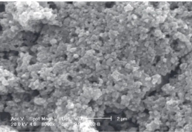
manganites have been published. In our investigations, La(1-x)SrxMnO3 powders have been prepared by high-tem-perature solid-state reaction of La2O3, SrCO3, and MnCO3. Figure 1 shows representative SEM micrograph of La0.60Sr0.40MnO3 powders prepared using traditional ceramic processing method.
The XRD patterns of the sintered samples indicated the formation of a single-phase solid solution with perovskite-like structure, where the Sr2+ ions are expected to occupy
La3+ sites. For samples sintered at 1400 °C, an orthorhombic
structure of La0.50Sr0.50MnO3 composition was determined14.
At 1500 °C, a slight modification to monoclinic structure of La0.60Sr0.40MnO3 composition was obtained. These compo-sitions such as La0.60Sr0.40MnO3 and La0.50Sr0.50MnO3 were prepared using traditional ceramic processing methods. The densities of these sintered samples (1500 °C for 4 h) are 91% of the theoretical density.
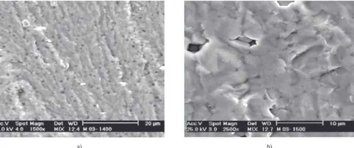
Figure 2 shows SEM micrographs of samples sintered at 1400 °C (La0.50Sr0.50MnO3) and 1500 °C (La0.60Sr0.40MnO3) for 4 h. The micrograph of the sample sintered at 1400 °C (Fig. 2a) shows small voids while the sample sintered at 1500 °C (Fig. 2b) shows large voids among aggregated lumps.
A literature study7,11 has proposed that the difference
be-tween Sr-doped lanthanum manganites and YSZ coefficients is not larger than 2.6 × 10⁻⁶deg-1. In this work, the thermal
expansion coefficient of La0.60Sr0.40MnO3 calculated from the slope of the curve was 12.8 × 10⁻⁶ C-1 at 1000 °C. In fact, this
result is very similar to that obtained for yttria stabilized zirconia, YSZ, (10.3 × 10⁻⁶ deg-1 in air), the electrolyte of
SOFC. Based on these results, it was demonstrated that the composition of La0.60Sr0.40MnO3 is one of the candidates adopted for use as SOFC electrode, because it was verified that these data are compatible with the value of the electro-lyte (YSZ) mentioned in the literature (10.3 × 10⁻⁶ deg-1). For
this composition, the value of the thermal expansion coeffi-cient diverges by no more than 2.6 × 10⁻⁶ deg-1.
However, an electrical conductivity of 4.634 Ω-1cm-1 for
La0.60Sr0.40MnO3 at 735 °C, with a sample density of 91% of
the theoretical value, was determined.
Coated films with 57 ± 0.3 µm of thickness were meas-ured by SEM and microstructural investigation of these multiple coatings shows pore shape and size (Fig. 3). The mean pore size is in the range of 1.6 to 2.6 µm.
Remarks: La0.60Sr0.40MnO3 composition has been ob-tained in the Fuel Cell Program at IPEN with adequate struc-tural and electrical specifications for use as cathode in solid oxide fuel cell. Cathode-electrolyte interface interactions have been studied with good results.
2.2. Electrolyte
Cubic stabilized zirconia (CSZ) is a pure oxygen ion conductor and the most common material used for solid oxide fuel cell electrolyte due to its availability and
rela-Figure 3. SEM micrograph of a porous cathode deposited via slurry coating on an electrolyte substrate.
218 Seo et al. Materials Research
tively low cost15. To achieve a good performance, powders
have been synthesized by the coprecipitation route16, using
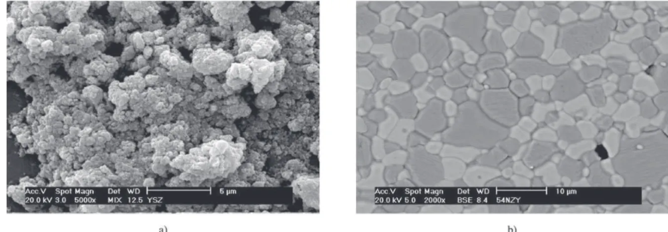
aqueous solutions of zirconium and yttrium pure salts or yttrium concentrates, mixed in the desired proportions. The use of yttria concentrates has been studied to reduce the product cost. The reaction is carried out with ammonia so-lution. To eliminate hard agglomerates the precipitate is fil-tered, washed with water and treated with organic solvents by azeotropic distillation. The mixed hydroxides are dried at 80 °C and calcined at 800 °C resulting in small particles grouped in soft agglomerates as is shown in Fig. 4a. The powders are pressed in cylindrical ceramic bodies and sintered at 1500 °C for 1 h. Figure 4b shows a SEM micro-graph of a thermally etched, CSZ ceramic with 9 mol % of yttria with cubic grain size at about 4 µm. The achieved ionic conductivity of this sintered product is near to 1.3 Ω-1cm-1 at
1000 °C.
Remarks: Sintered cubic stabilized zirconia with elec-trical specification for SOFC electrolytes was obtained.
2.3. Anode (Fuel Electrode)
The YSZ-Ni powders preparation has been investigated by two different routes, mechanical mixing of oxide pow-ders17 and a coprecipitation of metal salt solutions18. In the
first process, a commercial NiO powder and a zirconia-yttria prepared by the same process adopted for the electrolyte were used. The NiO powder was ground to about 1 µm, approximately the same size of the YSZ powder. Both ders were mixed in an agate mortar and the produced pow-ders were characterized by scanning electron microscopy. The surface area and the particle size were measured using the BET technique and the laser diffraction method, respec-tively. Figure 5a shows a typical ZrO2-Y2O3-NiO powder. These powders were then pressed as cylindrical pellets that were sintered at 1600 °C for 4 h. Zirconia with 8 mol%
yttria was chosen for this work, while the Ni content was in the range of 20 to 75 wt%. Figure 5b shows the SEM mi-crograph of a thermally etched YSZ-NiO composite with 54 wt.% NiO. Dark gray grains (NiO-rich phase) are large, indicating a fast grain growth, and the light gray grains are ZrO2 rich phases.
The coprecipitation process consists in a preparation of metal salt aqueous solutions that are mixed with the appro-priate proportions in an experimental apparatus. This mixed solution is sprayed in an ammonium hydroxide solution. The precipitate is then set to sedimentation and the concen-tration of remaining cations in the supernatant is analyzed by ICP spectrometry to determine the process yield. The precipitate is filtered and submitted to the same process of the electrolyte preparation. The ceramic powder is pressed as cylindrical pellets. The NiO phase must be reduced to form a continuous Ni metal phase. The reduction process is done with a hydrogen/argon gaseous mixture in a system assembled in a high temperature tube furnace.
2.4. Interconnect
Few oxide systems have been considered as SOFC in-terconnect material due to the stringent requirements for this fuel cell component. Lanthanum chromite (LaCrO3) is particularly suitable because of the high electronic conduc-tivity under fuel and oxidant atmospheres, stability in the fuel cell environment and compatibility with other cell com-ponents. A primary requirement for potential interconnect materials is the high density to prevent cross leakage of fuel and oxidant gases.
It is well known that the LaCrO3 is difficult to sinter to high densities under high oxygen activity conditions. The poor sinterability of LaCrO3 in air or oxidizing atmospheres has been ascribed to the formation of a thin layer of Cr2O3 (from CrO3 gases) at the inter-particle neck, during the
tial stage of sintering. Because of the high volatility of chro-mium oxides, in order to sinter LaCrO3 to high densities, firing temperatures higher than 1660 °C under low oxygen
partial pressures have been currently used19. The
densification process has been improved by the use of sintering additives or powders which are highly reactive (high surface area)19, 20.
At IPEN, the research on interconnect materials has been focused on two different synthesis routes using two kinds of starting materials, national and imported ones. In tion it has been studied the influence of the sintering addi-tives on the final properties of the LaCrO3.
Lanthanum chromite with 30 mol% cobalt (LaCr0.7Co0.3O3) has been synthesized by two different meth-ods: the conventional mechanical mixing of the powders and the combustion reaction.
XRD patterns of as-synthesized powders showed peaks of the LaCr0,7Co0.3O3 crystalline phase, that were related to both routes studied.
LaCr0.7Co0.3O3 powders, resultant from the mechanical mixing route and after the calcination treatment, presented agglomerate size of 1.29 µm (sample A) and 1.44 µm (sam-ple B) for pure and concentrated oxides, respectively. For powders obtained by the combustion reaction synthesis, the agglomerate size was 7.38 µm (sample C). Studies on com-bustion synthesis process21 have been attributed this
differ-ence to the related energies during the chemical reactions. The SEM micrograph of the sample (Fig. 6) reveals agglom-erates constituted by interconnected nanoparticles.
The density values of the samples A, B and C, sintered at 1500 °C for 3 h in air atmosphere, were 99.1, 98.4 and 85.8 % of the theoretical density, respectively. The differ-ence in the density values reveals that the synthesis process interferes markedly on final properties of the sintered mate-rial. The greatest density difference arises from the
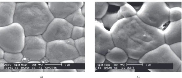
agglom-erated primary particles of the powders synthesized by com-bustion reaction. SEM micrographs of the polished and ther-mally etched surfaces of the sintered samples (Fig. 7) show an homogeneous and uniform microstructure for the ceramic obtained from powders prepared by mechanical mixing (Fig.7a) and reaction combustion route (Fig. 7b).
The electrical resistivity measurements of the LaCr0.7Co0.3O3 pellets were performed by the two points technique. The resis-tive electrical behavior as a function of the temperature of the samples synthesized by the different synthesis processes routes reveals the influence of the sintered density. The samples A and B have presented resistivity values (at 250 °C in air atmos-phere) of 1.86 and 1.97 Ω.m, respectively; while the sample C (combustion reaction process) showed 0.8197 Ω.m at the same measurement conditions.
Remarks: Both synthesis routes are able to produce LaCr0.7Co0.3O3 powders that result in ceramics with high densities and adequate electrical characteristics for
inter-Figure 5. SEM micrograph of the YSZ-12.5%wt NiO powder (a); the thermally etched YSZ-54wt% NiO ceramic (b).
220 Seo et al. Materials Research
connect fuel cells applications. However the combustion re-action method with the optimized variables may result in a simpler, faster and more economic route to produce a ho-mogeneous powder with nanometric dimensions.
Summary:In this paper materials and their synthesis processing investigated at IPEN in a SOFC research pro-gram has been reported. The aim of the project is stationary electric power generation. The materials studied were yttria-stabilized zirconia (YSZ) as the electrolyte, strontium-doped manganite as the cathode, nickel-YSZ cermet as the anode and cobalt-doped lanthanum chromite as interconnect. These materials have been used in the most SOFC systems known for operating temperatures around 1000 °C. The future di-rection of this program deals with the ceramic processing technology of a planar SOFC stack, where the electrolyte or the anode ensures the mechanical stability of the cells. Slurry deposition techniques and co-firing processes have been investigated for this purpose.
Acknowledgements
The authors wish to thank FAPESP/SP/Brazil and CNPq/ Brazil for financial support.
References
1. Minh, N.Q. J. Am. Ceram. Soc., v. 76, p. 563-588, 1993. 2. Koch Soren, Contact Resistence of Ceramic Interfaces Between Materials Used for Solid Oxide Fuel Cell Ap-plications, PhD Thesis from Technical University of Denmark at the Department of Chemistry, may, 2002. 3. Kilbride, I.P. J. Power Sources, v. 61, p. 167-171, 1996. 4. Kim, J.-W.; Virkar, A.V.; Fung, K.-Z.; Mehta, K.; Singhal,
S.C. J. Electrochem. Soc., v. 146, p. 69-78, 1999. 5. Singhal, S.C. Solid State Ionics, v. 135, p. 305-313, 2000.
6. Badwal, S.P.S.; Foger, K. Materials Forum, v. 21, p. 187-224, 1997.
7. Mori; M.; Hiei; Y.; Sammes, N.M.; Tompsett, G.A. Electrochem. Soc. Proc.,v. 99, p. 347-351, 2000. 8. Park, H.B.; Hong, Y.S.; Kim, S.J. J. Am. Sci. Letter,v. 16,
p. 1782-1785, 1997.
9. Taimatsu, H.; Wada, K.; Kaneko, H.A. J. Am. Ceram. Soc.,v. 75, p. 401, 1992.
10. Huang, K.; Feng, M.; Goodenough, J.B.; Schmerling, M. J. Electrochem. Soc.,v. 143, p. 3630, 1996. 11. Hammouche, A.; Siebert, E.; Hammou, A. Mater. Res.
Bull., v. 24, p. 367, 1989.
12. Kuo, J.H.; Anderson, H.U.; Sparlin, D.M. J. Solid State Chem., v.87, p. 55, 1990.
13. Yamamoto, O.; Takeda, Y.; Kanno, R.; Noda, M. Solid State Ionics, v. 22, p. 241-246, 1987.
14. Gharbage, B.; Henaultet, M.; Pagnier, T.; Hammou, A. Mat. Res.Bull., v. 26, p. 1001, 1991.
15. Segal, D. Key. Eng. Mater, v. 153-154, p. 241-250, 1998. 16. Lazar, D.R.R.; Menezes, C.A.B.; Ussui, V.; Bressiani, A.H.A.; Paschoal, J.O.A. J. Eur.Ceram.Soc., v. 22, p. 2813-2820, 2002.
17. Park, Y.M.; Choi, G.M. Solid State Ionics, v. 120, p. 265-274, 1999.
18. Marinsek, M.; Zupan, K.; Macek, J. J. Power Sources, v. 86, p. 383-389, 2000.
19. Groupp, L.; Anderson, H.U. J.Am. Ceram.Soc., v. 59, p. 49-50, 1976.
20. Chick, L.A.; Bates, J.L.; Pederson, L.R.; Kissinger, H.E. Proceeding of the First International Symposium on Solid
Oxide Fuel Cells. Ed. By S.C. Singhal. The
Electrochemical Society, Pennington, NY, p.170-87, 1989. 21. Segadães, M.; Morelli, M.R.; Kiminami, R.G.A. J. Eur.
Ceram. Soc., v. 18, p. 771-781, 1998.