Pedro Maria Caetano Lopes de Carvalho e Rêgo
[Nome completo do autor]
[Nome completo do autor]
[Nome completo do autor]
[Nome completo do autor]
[Nome completo do autor]
[Nome completo do autor]
[Nome completo do autor]
Licenciatura em Engenharia de Materiais
[Habilitações Académicas] [Habilitações Académicas] [Habilitações Académicas] [Habilitações Académicas] [Habilitações Académicas] [Habilitações Académicas] [Habilitações Académicas] Setembro, 2019
Production and Characterization of Electroactive Polymeric
Membranes by Electrospinning
[Título da Tese]
Dissertação para obtenção do Grau de Mestre em Engenharia de Materiais 2018/2019
Dissertação para obtenção do Grau de Mestre em [Engenharia Informática]
Orientador: Professor Doutor Rui Alberto Garção Barreira do Nascimento Igreja, Professor Auxiliar, Faculdade de Ciências e Tecnologia da Universidade Nova de Lisboa Co-orientador: Professor Doutor João Paulo Miranda Ribeiro Borges, Professor Associado com
I
Production and Characterization of Electroactive Polymeric Membranes by Electrospinning Copyright © Pedro Maria Caetano Lopes de Carvalho e Rêgo, Faculdade de Ciências e Tecnologia, Universidade Nova de Lisboa.
A Faculdade de Ciências e Tecnologia e a Universidade Nova de Lisboa têm o direito, perpétuo e sem limites geográficos, de arquivar e publicar esta dissertação através de exemplares impressos reproduzidos em papel ou de forma digital, ou por qualquer outro meio conhecido ou que venha a ser inventado, e de a divulgar através de repositórios científicos e de admitir a sua cópia e distribuição com objectivos educacionais ou de investigação, não comerciais, desde que seja dado crédito ao autor e editor.
III
“The difference between screwing around and science is writing it down.”
Adam Savage
“Research Wisdom. Those who Explore and never fail were never on the Frontier to begin with.”
V
Agradecimentos
Em primeiro lugar, gostaria de agradecer ao Professor Doutor Rui Igreja por aceitar-me como seu aluno a orientar, pela confiança demonstrada em mim, por toda a ajuda, conhecimento e profissionalismo que me prestou e ensinou durante este período.
Ao Professor Doutor João Paulo Borges, meu co-orientador, primeiramente por todo o trabalho e tempo dedicado a este curso, dando tudo e nunca desistindo dos seus alunos. Em segundo lugar, por me aceitar como seu orientando, por toda a ajuda disponibilizada quando o ia chatear, “socorro” quando eu já não sabia o que fazer e como me desenvencilhar de alguns problemas, e me ter motivado nos momentos em que a tese me tinha deixado perdido. Foi um verdadeiro prazer ter aprendido tanto consigo ao longo destes anos.
Agradecer a todos os Professores do Departamento de Ciência dos Materiais por todo o conhecimento transmitido e profissionalismo.
Agradecer à Andreia dos Santos, que apesar de não ser minha co-orientadora quase podia ser, por estar sempre disponível para me tirar dúvidas e ajudar no que eu precisasse.
Agradecer a todas as pessoas que me acompanharam e ajudaram no laboratório ao longo deste tempo e se tornaram meus amigos, ao Ricardo Matos, ao João Lavadinho, à Ana Pádua, à Bárbara Silva, à Catarina Chaparro, e em especial à Adriana Gonçalves.
Agradecer ao Birra, Castor, Luís, Rodrigo, Di, Rafa, Jota, Nunadas e Beto que me acompanham há muito tempo e estão sempre presentes, mesmo quando eu aparecia menos vezes.
Além, Beja, Dias, Fred, Gui, Henrique, Magda, Moniz e Moura, OBRIGADO por fazerem destes anos e este percurso o melhor da minha vida. Tornaram-se a minha segunda família, partilharam momentos importantes comigo e estiveram sempre lá quando precisei, e por isso levo-vos para sempre comigo.
Mãe e Pai, obrigado por fazerem tudo por mim e darem tudo sem olhar a meios, mesmo quando acabam por sair prejudicados. Por toda a educação dada e valores transmitidos, fazendo de mim uma melhor pessoa. Agradecer à restante família por estarem sempre presentes nos bons e maus momentos.
VII
Resumo
Nas últimas décadas o desenvolvimento na miniaturização de dispositivos tornou-se uma área muito importante para o futuro da tecnologia. Apesar da miniaturização de dispositivos ser bem sucedida na diminuição do tamanho dos dispositivos, o mesmo não pode ser dito sobre as suas fontes de energia. Trabalho recente no campo dos nanomateriais começou a mostrar algum progresso no sentido de fontes de energia auto-alimentadas que geram a sua energia a partir do meio ambiente que as rodeia. Esta energia pode ser “recuperada” da energia solar, térmica, mecânica, etc. Os avanços nesta área mostram que é possível gerar esta energia ambiente utilizando nanomateriais com diferentes arquitecturas: nanofios, nanofibras e filmes.
Neste trabalho, membranas de nanofibras produzidas por electrofiação foram utilizadas como nanogeradores. A electrofiação é um método fácil, de baixo custo e escalável de produzir nanofibras. As fibras e membranas produzidas podem ter diferentes morfologias, espessuras e são leves, sendo assim boas candidatas para dispositivos miniaturizados e wearables, etc.
As membranas de nanofibras foram produzidas a partir de Poly(vinylidene
fluoride-co-trifluoroethylene) (P(VDF-co-TrFE)), que é um material polimérico electroactivo com boas
propriedades piezoeléctricas e piroeléctricas, e que é usualmente utilizado como gerador de energia. A geração de energia está altamente associada com a estrutura cristalina da sua fase β.
Três materiais diferentes (Tinta de Carbono, PEDOT:PSS e Alumínio) foram utilizados para criar os contactos eléctricos deste nanogerador. Os contactos foram depositados por electrofiação (PEDOT:PSS), aerógrafo (Tinta de Carbono e PEDOT:PSS) e por evaporação térmica (Alumínio).
Caracterizou-se o comportamento e as propriedades dos materiais e do dispositivo utilizando DSC, DRX, FTIR, Constante Piroeléctrica, Espectroscopia de Impedância, Ensaios de Tracção, etc.
O processo de electrofiação não levou ao aumento da fracção de fase β nem à orientação dos domínios de dipolos. A deposição por aerografia de PEDOT:PSS foi o único processo que produziu um contacto eléctrico apto a ser utilizado num dispositivo.
Após a polarização, o dispositivo apresentou uma resposta piroeléctrica, mostrando que o processo de polarização melhorou as propriedades electroactivas do polímero.
Palavras-chave: Electrofiação, Fibras, Membranas, P(VDF-co-TrFE), Electroactivo, Piroeléctrico, Deposição, PEDOT:PSS, Tinta de Carbono, Alumínio, Dispositivo
IX
Abstract
In the last decades the development in miniaturization of devices has become a very important topic for the future of technology. Although the miniaturization of devices has been successful in de-creasing the size of devices, the same can not be said about their energy sources. Recent work in the nanomaterials filed has started to show some progress in the towards self-powered energy sources that generate power form the environment that surrounds them. This energy can be scavenged from solar, thermal, mechanical, etc. The advances in this area shows that is possible to generate this environmental energy using nanomaterials with different architectures: nanowires, nanofibers and films.
In this work nanofibrous membranes produced by electrospinning were used as nanogenerators. Electrospinning is a low-cost, easy and scalable methods to produce nanofibers. The fibres and mem-branes produced can have different morphologies, thicknesses and are lightweight, therefore being good candidates for miniaturized devices and wearables, etc.
The nanofiber membranes were produced with Poly(vinylidene fluoride-co-trifluoroethylene) (P(VDF-co-TrFE)), which is a polymeric electroactive material with good piezoelectric and pyroelec-tric properties, and is commonly used has an energy generator. The energy generation is highly associ-ated with the crystalline structure of its β-phase.
Three different materials (Carbon Paint, PEDOT:PSS and Aluminium), were used to create the electric contacts of this nanogenerator. The contacts where deposited by electrospinning (PEDOT.PSS), airbrush (Carbon Paint and PEDOT:PSS) and by thermal evaporation (Aluminium).
DSC, XRD, FTIR, Pyroelectric Constant, Impedance spectroscopy, Tensile Strength, etc. were used to characterize the behaviour and properties of the materials and device.
The electrospinning process did not show any increase in β-phase fraction and the dipoles do-mains orientation. Airbrush deposition of PEDOT:PSS was the only process that produced an electric contact capable of being used on a device.
After poling, the device displayed a pyroelectric response, thus showing that the poling process improved the electroactive properties of the polymer.
Keywords: Electrospinning, Fibres, Membranes, P(VDF-co-TrFE), Electroactive, Pyroelectric, Deposition, PEDOT:PSS, Carbon Paint, Aluminium, Device
XI
Content Table
AGRADECIMENTOS ... V RESUMO ... VII ABSTRACT ... IX CONTENT TABLE ... XI LIST OF FIGURES ... XIII LIST OF TABLES ... XV ABBREVIATIONS AND SYMBOLS ... XVIIMOTIVATION AND OBJECTIVES ... 1
INTRODUCTION ... 2 Piezoelectric materials ... 2 Electroactive polymers ... 2 PVDF and co-polymers ... 3 Poling ... 5 Pyroelectricity ... 5 Electrospinning ... 5
MATERIALS AND METHODS ... 7
1. PRODUCTION METHODS ... 7
Production of Electroactive Membranes from P(VDF-co-TrFE) ... 7
Electric Contacts Deposition... 7
Poling and hysteresis loop ... 8
2. CHARACTERISATION ... 9
Membrane ... 9
Electric, Dielectric and Electroactive Measurements ... 9
RESULTS AND DISCUSSION ... 10
1. P(VDF-CO-TRFE)MEMBRANE... 10
Morphology and Mechanical Properties ... 10
β-phase Identification ... 13 2. ELECTRIC CONTACTS ... 17 Deposition ... 17 Electric Characterization ... 20 3. ELECTRIC MEASUREMENTS ... 21 Electroactivity... 21 Dielectric ... 24
CONCLUSION AND FUTURE PERSPECTIVES ... 26
BIBLIOGRAPHY ... 27
ADDITIONAL INFORMATION ... 31
XIII
List of Figures
Figure 1 – PVDF α, β and γ phases structures [3] ... 4
Figure 2 – P(VDF-co-TrFE) chemical structure [7] ... 4
Figure 3 – Schematic of the poling process ... 5
Figure 4 – Poling system setup ... 8
Figure 5 – Pyroelectric measurement setup ... 9
Figure 6 – Electrospun P(VDF-co-TrFE) membrane ... 10
Figure 7 – SEM of membrane and relative distribution of fibre diameter. Average diameter of fibres is... 11
Figure 8 – P(VDF-co-TrFE) electrospun membrane Tensile Test ... 12
Figure 9 – FTIR of P(VDF-co-TrFE) powder and electrospun membrane ... 13
Figure 10 – XRD of P(VDF-co-TrFE) powder and electrospun membrane ... 15
Figure 11 – DSC of P(VDF-co-TrFE) powder and electrospun during heating ... 16
Figure 12 – Electrospun PEDOT:PSS membrane on top of a P(VDF-co-TrFE) membrane. (a) top; (b)bottom .. 17
Figure 13 – Airbrushed PEDOT:PSS and carbon paint on P(VDF-co-TrFE) membranes. (a) Membrane airbrushed with PEDOT:PSS and mask; (b) Membrane airbrushed with carbon paint; (c) Sample device with airbrushed PEDOT:PSS; (d) Sample device with airbrushed carbon paint ... 18
Figure 14 – SEM images of (a) Underside of P(VDF-co-TrFE) membrane with PEDOT:PSS; (b) Underside of P(VDF-co-TrFE) membrane with Carbon Paint. ... 19
Figure 15 – P(VDF-co-TrFE) membrane with aluminium contact deposited by thermal evaporation ... 19
Figure 16 – Electrospun membranes with (a) PEDOT:PSS and (b) Carbon paint deposited by airbrush used to measure the sheet resistance. ... 20
Figure 17 – P(VDF-co-TrFE) with airbrushed PEDOT:PSS device hysteresis cycle ... 21
Figure 18 – Schematic of the behaviour of a ferroelectric during Poling ... 22
Figure 19 – Pyroelectric effect before and after Poling. A) before poling; B) after poling ... 23
Figure 20 – Dielectric Impedance of electrospun P(VDF-co-TrFE) membrane with airbrushed PEDOT:PSS contacts before and after poling ... 24
Figure 21 – Dielectric Capacitance of electrospun P(VDF-co-TrFE) membrane with airbrushed PEDOT:PSS contacts before and after poling ... 24
Figure 22 – Tensile tests ... 31
XV
List of Tables
Table 1 – Relative permittivity and piezoelectric coefficients of different polymers and ceramics ... 3
Table 2 – Average mechanical properties of the membranes ... 12
Table 3 – Absorption FTIR bands characteristics of β-phase ... 13
Table 4 – Fraction of β-phase in the P(VDF-co-TrFE) powder and the electrospun membrane ... 14
Table 5 – Diffraction angle and crystal plane of β -phase ... 15
Table 6 – Curie and Melting Temperatures of the P(VDF-co-TrFE) membrane ... 16
Table 7 – Measurements of sheet resistance of with PEDOT:PSS and Carbon paint deposited by airbrush on top of electrospun membranes ... 20
Table 8 - Deposition methods and materials characteristics... 21
Table 9 – Pyroelectric Coefficient... 23
XVII
Abbreviations and Symbols
EAPs Electroactive Polymers
PVDF Polyvinylidene fluoride
P(VDF-co-TrFE) Poly(vinylidene fluoride-co-trifluoroethylene)
PEO poly(ethylene oxide)
PEDOT:PSS Poly(3,4-ethylenedioxythiophene)-poly(styrenesulfonate)
DMF Dimethylformamide
DMSO Dimethylsulfoxide
SEM Scanning electron microscope
FTIR Fourier-transform infrared spectroscopy
XRD X-Ray Diffraction
DSC Differential scanning calorimetry
T Temperature
TC Currie Temperature
TM Melting Temperature
E Young Modulus
σy Yield Strength
σUTS Ultimate Tensile Strength
ip Pyroelectric current p Pyroelectric Coefficient A Area d Thickness t Time K Kelvin ºC Celsius Degrees |Z| Impedance magnitude C Capacitance
tan δ Loss tangent
𝜀𝑟 Dielectric constant
F Farad
1
Motivation and Objectives
In this modern age of technology, where everyone has access to a numerous array of different devices with the most diversified applications, the scale of these devices has become a subject with increasing importance.
In the last decades the miniaturization of devices has suffered a great boost due to the work done in the nanoscience and nanotechnology fields, which has decreased the size of electronic components. Although this has happened to batteries and circuitry, the same can not be said about their energy sources.
Recent work in these fields has started to show some progress towards scale reduction using self-powered energy sources that scavenge power from the environment and generate electricity for devices. The advances in this area show that nanomaterials with different architectures, being films, nanofibers, or nanowires, can scavenge energy from mechanical, solar, thermal, etc.
EAPs are polymeric materials with electroactive properties, meaning that they can transform an environmental and mechanical stimulus in electric current, and vice-versa. P(VDF-co-TrFE) is an elec-troactive polymer that has good properties related to energy generation, and can be used as an actuator, sensor or generator. When associated with electrospinning, which is a production technique that makes thin, flexible and lightweight membranes out of stacked nanofibres, it produces good solution to imple-ment as an energy generator for miniaturized devices.
In this thesis the main objective is to make a self-powered energy source based on an electrospun membrane produced from an electroactive polymer with deposited electric contacts that can scavenge power from the environment, mainly thermal variations.
To achieve this objective, the following topics were addressed:
• Produce electroactive membranes by electrospinning and characterize them;
• Demonstrate that the electrospinning process does not, or barely does, create β-phase and induce the poling of electroactive fibres and membranes produced;
• Test different types of depositions methods and materials to act as electric contact; • Polarize electrospun membranes fabricated and characterize their electroactive and
2
Introduction
The capacity of utilizing energy harvesting to produce self-powered systems is interesting be-cause it can help to reduce the dependency of external power or batteries that need to be frequently charged or replaced.
Piezoelectric and pyroelectric materials have the capability of converting mechanical stimuli, direct piezoelectric effect, or thermal variation, pyroelectric effect, into electric energy. As the two properties are normally simultaneously present, this creates the possibility of producing a hybrid sys-tem.
Piezoelectric materials
The direct piezoelectric effect happens when a material is subjected to a mechanical stress and its electric polarization changes creating an electric current in a circuit which can be harvested. This property can be used to produce self-powered devices, sensors, etc. On the other hand, when a field is applied on the piezoelectric material, it presents a mechanical strain, which is denominated converse piezoelectric effect. This effect can be explored to fabricate acoustic emitters, actuators, etc.
The mechanism occurs due to the crystallinity of the material and the ions distribution inside the unit cells, since the positives and negative charges are not symmetrically centred inside the unit cell planes when no stress is applied. The lack of symmetry of the ion distribution in these crystalline ma-terials results in the existence of electric dipoles and consecutively in the piezoelectric response.
Ferroelectric materials are a subclass of piezoelectric materials characterized by their natural polarization while relaxed and their capacity of reorient the polarization direction through the applica-tion of an electric field. They contain groups of crystallographic unit cells that share a common polari-zation direction, denominated ferroelectric domains. The domains are randomly orientated in relation to each other’s, so there is no net polarization through the materials, and the material does not show piezoelectric behaviour. For the material to exhibit piezoelectric properties, the dipoles need to be ori-ented to a common direction via ‘poling’ process.
Electroactive polymers
Electroactive polymers have advantages against ceramics due to the ease of processing at low temperatures, flexibility, ductility, elasticity, low density, etc., and possibility of being biocompati-ble.[1] Furthermore, they can be fabricated in a large variety of shapes. But they also have lower pie-zoelectric coefficients and permittivity (as shown on Table 1).
3
The electric dipoles of these materials can be oriented when an electric field is applied, with or without temperature and stretching, leading to piezoelectric and pyroelectric behaviour.
The electroactive behaviour highly relies on their crystalline structure, this meaning that the conformation of the polymeric chain, the dipolar orientation on the crystalline regions, processing con-ditions and post-treatment are of high importance.[2, 3]
PVDF and co-polymers
PVDF is an electroactive polymer most commonly used do to his high piezoelectric coefficient when compared to other electroactive polymers.
It’s a thermoplastic and ferroelectric polymer with a semicrystalline structure that can vary due to different conformations of its molecular structure causing different phases. This capability to present different conformations of the polymeric chain is responsible for the existence of five distinct phases, each one with different dielectric contributions. The α e ε are the only ones of the five to not show dipolar moment because of the anti-parallel dipole packing. On the other hand, the γ, δ and β phases exhibit dipolar moment, being β phase the one that shows a bigger moment, 8 x 10-30 Cm, due to the
fluorine atoms electronegativity when compared to hydrogen and carbon atoms and their conformation, creating a strong electric dipolar moment. [2–4]
Polymer Relative permittivity (εr) (frequency measurement) dij (pC.N-1) PVDF 6−12 d31 = 8−22 d33 = -24 to -34 P(VDF-co-TrFE) 18 d31 = 12 to 25 d33 = -25 to 4 P(VDF-co-HFP) 11 d31 = 30 d33 = -24 P(VDF-co-CTFE) 13 d33 = -140 P(VDF-TrFE-CFE) 65 --- Polyurethane 6,8 --- Polyamide 11 5 d33 = 4 Polyamide --- d33 = 2,5−16,5 Poly-L-lactide 3−4 d14 = -9,82 Polyhydroxybutyrate 2−3,5 d33 = 1,6−2,0
Liquid crystal elastomers --- d33 = -70
Parylene-C --- d33 = 0,1−2
ZnO --- d33 = 12,4
PZT 500 d33 = 225−590
BaTio3 1200 d33 = 191
Table 1 – Relative permittivity and piezoelectric coefficients of different polymers and ceramics (adapted from [1])
4
The PVDF homopolymer has a higher molecular weight of fluorine than hydrogen. So, the presence of fluorine atoms, which have a bigger Van der Waals radius (1,35 Å against hydrogen’s 1,2 Å) and the electronegativity of the [–CH2 – CF2–] chain causes a dipolar momentum perpendicular to the chain in each monomer unity. [3, 5]
The introduction of co-monomers, such as TrFE, facilitates the formation of the ferroelectric phase because of the steric hindrance effect, thus P(VDF-co-TrFE) possesses a higher quantity of β-phase and consequently better electroactive (piezoelectric and pyroelectric) properties. [6]
[7]
Ferroelectric materials are limited by the Curie temperature (TC), so when heated above this
temperature, the ferroelectric β-phase of PVDF is converted into a paraelectric α-phase.
PVDF and its co-polymers are well known examples of ferroelectric materials. P(VDF-co-TrFE) is a crystalline co-polymer of PVDF, with polarity that occurs due to the alignment of the cova-lent bond of its molecular chains.
Considering that pyroelectric materials need to have dipoles and exhibit a certain level of po-larization, all pyroelectric materials are consequently piezoelectric. Ferroelectrics are a subgroup of pyroelectrics, therefore they are also a subclass of piezoelectric materials, exhibiting both pyro and piezoelectric effects.
Since the piezo and pyroelectric effect are consequence of the electric molecular dipoles of the polymer, it’s necessary to increase the non-symmetric ferroelectric β-phase to maximize the coefficients and effects.
Figure 1 - PVDF α, β and γ phases structures [3]
5
Poling
Poling is essential to orient the dipoles and turn an inactive ferroelectric material into a material with electroactive properties. It involves the application of an electric field to orient the domains’ polar axis to a common direction close to that of the electric field. Usually the polarization axis is perpendic-ular to the thickness of the material.
To ease and improve the poling of ferroelectrics, the material can be heated to a temperature beneath the Curie temperature.
Pyroelectricity
Pyroelectric materials, like the piezoelectrics, also have a natural polarization, but resulting from the alignment of the polarized covalent bonds. Although the electric charge generation is similar to the piezoelectric effect, in the piezoelectric effect the charge generation outcomes from a thermal variation that changes the level of polarization due to thermal vibration of the dipoles.[8]
Electrospinning
Electrospinning is a (submicron/nano) fibre fabrication process, in large scale, that emerged in the beginning of the XXI century along with the developments in Nanotechnology and Nanoscience.[9]
Nanofibres are one-dimensional structures that display one of its dimensions at nanoscale.[10] Due to their diameter, these nanofibres have a large surface area to volume ratio and unique properties that can be interesting in biomedical, textile, electronic fields.
This technique utilizes a high-voltage power supply that creates an electric field to stretch the jet of a solution towards a target where the fibres are collected and form a membrane. Although being a relatively simple technique, electrospinning depends on several parameters that can affect severely the morphology of the fibres. With this process is possible to obtain polymeric, metallic, ceramic and hybrid fibres. Electrospun fibres are deposited layer-by-layer forming a membrane and therefore electrospin-ning can be considered an additive manufacturing technique. [10–13]
The temporary application of high electric fields contributes to the residual polarization of crys-talline domains in PVDF. [14, 15] This may occur in distinct circumstances. On the first one, at rela-tively low electric fields, the crystalline domains (dipoles) are aligned in the same direction as the
6
applied field. On the second one, a high electric field associated with fibre stretching promotes the transformation of the non-polar phases through change in the molecular conformation into the ferroe-lectric β-phase. This is, the high eferroe-lectric field and stretching act as the poling process and may increase the β-phase fraction of the polymer, thus increasing the electroactive properties. [16–19]
The electrospun membranes produced by electrospinning are low-cost, simple, easy to produce, lightweight, flexible, with variable thickness and morphology, biocompatible, etc., therefore they pos-sess a good combination of characteristics that make them an effective solution to replace complex generators as a source of energy.
These membranes can act as nanogenerators and be used on small devices and wearables that demand low energy to operate.
Some work as already been done with electrospun PVDF co-polymers, such has P(VDF-co-TrFE), for textile, energy harvesting, sensor, batteries, biomedical (internal and exterior) applications. [20–27]
7
Materials and Methods
1. Production Methods
Production of Electroactive Membranes from P(VDF-co-TrFE)
A solution for production of fibres through electrospinning was prepared by dissolving 20 wt% (P(VDF-co-TrFE)), with unknown Mw from Solvay, on a Dimethylformamide and Acetone (8:2) solu-tion for 4 hours in a bath at 60 ºC with steering. [28]
1.1.1. Electrospinning
The previously prepared solution was dispensed at a constant flow rate of 0,5 ml/h and with a 15 kV electric potential difference applied. The collector used was a simple metallic target made with a piece of aluminium foil, for easy removal of the sample membrane, placed at 15 cm from the needle. The setup was encapsulated inside an acrylic box to control the environmental conditions allowing the temperature to remain between 22 ºC and 26 ºC, and the humidity between 35 % and 40 %.
The distance from the needle to the target, the electric potential difference and the flow rate were all optimized in order to achieve the best possible fibres and membranes.
A target constituted by two metallic electrodes, placed parallel to each other, was also used with the intent of facilitating the deposition of the electric contacts on both sides of the membrane. This method created a membrane with fibres aligned perpendicularly to the metallic electrodes, but the mem-brane was too thin and with bad reproducibility, being abandoned.
Electric Contacts Deposition
Three different approaches to deposit the electric contact were attempted, electrospinning, Air-brush painting and thermal deposition. The PEDOT:PSS was “Clevios PH1000” bought from “Heraeus Deutschland GmbH Co., Germany”.
1.2.1. Electrospinning
A PEDOT:PSS solution was produced based on the work of Bessaire et al. using PEO as a means to help produce fibres. [29] This solution did not work as described, so 0,1 ml of DMF and 0,250 ml of
Ethanol were added. To obtain an optimized fibre production, the target was placed at 20cm from the
needle tip, with 15kV electric potential difference and a flow rate of 0,25 ml/h. These parameters were optimized for the same environmental conditions as before. For this deposition, a collector with already deposited P(VDF-co-TrFE) membrane was used in order to directly deposit the electric contact pro-duced on top of the electroactive membrane.
8
1.2.2. Airbrush
In this case the electric contacts were deposited utilizing an airbrush and a mask with 1 cm di-ameter circular cut-outs. The deposition was done with a constant air flow rate of 5 L/min and at a fixed distance of 10 cm to obtain a uniform layer and identical in every sample.
The carbon paint was used as it came, with no preparation, and after deposition only needed to be annealed at 85 ºC for 30 minutes.
For the PEDOT:PSS deposition, a solution was made of 95% PEDOT:PSS and 5% DMSO. The DMSO was added in order to increase/improve the electrical conductivity. [30][31]
1.2.3. Thermal Evaporation
Thermal evaporation was used to deposit a 100 nm thick layer of Aluminium.
Poling and hysteresis loop
Poling was done to orient the dipoles into a single direction in order to increase the piezoelectric and pyroelectric properties. The membrane was submerged in silicon oil at 90 ºC and a 3 kVpp voltage
with 0,5 Hz (maximum value without dielectric breakdown) signal was applied.
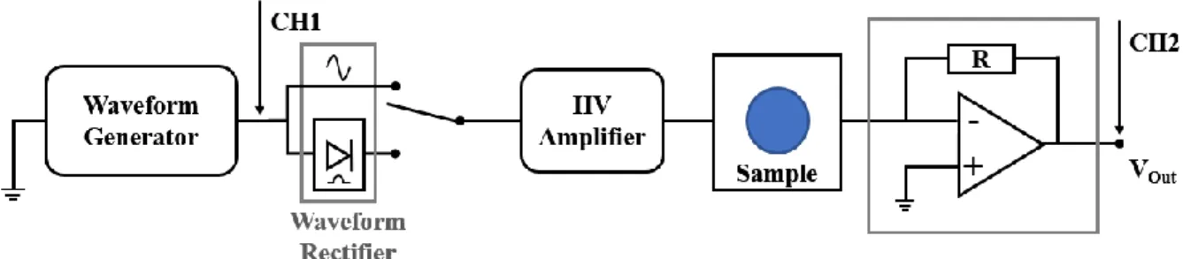
The poling system is shown in Figure 4. A function generator (Aim-TTi TGA 12104) is used to generate a small amplitude voltage which is them amplified by a TREK 610C. The high voltage signal is then applied to the sample which is connected to a transimpedance amplifier to allow the current to be measured. This configuration was used to measure the hysteresis loop. For poling, the small voltage signal goes through a rectifier (half wave rectifier) prior to the HV amplifier.
9
2. Characterisation
Membrane
2.1.1. Morphology and Mechanical Properties
Scanning electron microscopy (SEM) was performed to examine the fibre morphology and the membrane surface. Tensile tests were done to analyse the mechanical behaviour of the membrane and ascertain that it possesses good properties for the its purpose.
2.1.2. β-phase Identification
As said before, the β-phase is the most electroactive phase in PVDF and its co-polymers.
P(VDF-co-TrFE) should already be a co-polymer with high β-phase presence, so in order to verify the existence
of this electroactive ferroelectric phase, FTIR, XRD and DSC was done.
Electric, Dielectric and Electroactive Measurements
Sheet resistance was used to characterize the electric conductivity of the deposited contacts on the electrospun membrane surface.
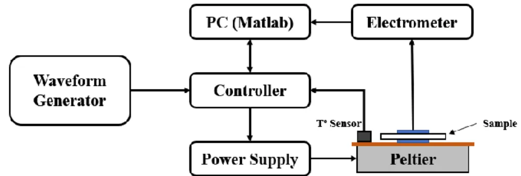
Impedance spectroscopy, using an auto balanced LCR Bridge (Agilent 4294A), was used for dielectric characterization. An in-house pyroelectric measurement system was used to determine the pyroelectric coefficient. The system is shown in Figure 5.
10
Results and Discussion
1. P(VDF-co-TrFE) Membrane
Morphology and Mechanical Properties
1.1.1. Electrospinning
Every membrane was produced by electrospinning 1ml of the prepared P(VDF-co-TrFE) solu-tion. The membranes obtained are porous, lightweight, flexible, slightly stretchable and thin, with an average thickness of 0,054 mm.
The membranes present some accumulated static electricity that may be resultant of electric po-tential difference applied on the fibres during the electrospinning process and the electroactive proper-ties of the polymer.
Figure 6 – Electrospun P(VDF-co-TrFE) membrane 1cm
11
1.1.2. SEM - Scanning Electron Microscopy
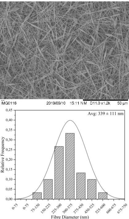
Through Scanning Electron Microscopy was possible to observe that the membrane is formed by stacked nanofibres randomly orientated. As expected, the stacking of the fibres reveals that the membrane is porous. Some fibres present stretched beads that may occur because the flow rate of dispensed solution is too high, the electric potential difference is too low, the distance to the target is too far or the solution viscosity is too low. Nevertheless, the fibre diametre is consitent througout the membrane and average fibre diameter is 339 ± 111 nm.
Figure 7 - SEM of membrane and relative distribution of fibre diameter. Average diameter of fibres is 339 ± 111 nm
12
1.1.3. Tensile Test
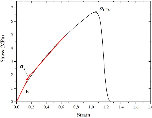
The tensile tests were done to mechanically characterize the membrane in order to ascertain if the mechanical properties suit their purpose. The tests were performed on 8 samples (shown in Addi-tional information chapter), 2 cm long and 1 cm wide, at 6 mm/s. The membrane presents an average Young modulus of 10,823 ± 1,904 MPa, determined by the slope of the elastic region (see Figure 8). It fractures at a stress of 7,870 ± 0,763 MPa and a strain of 1,322 ± 0,195. The yield strength was deter-mined from the intersection of the tangents to the stress-strain curve in the elastic and plastic regimes. These properties are similar to those of human skin, making the membrane a good option to be used in biomedical applications, for example. [32]–[34]
Table 2 – Average mechanical properties of the membranes
Young Modulus (MPa) Yield Strength (MPa) Ultimate Tensile Strength (MPa) Strain at UTS Average 11 1,8 7,9 1,3 Literature 6 - 22 - 5 – 32 1,2 – 2,2
13
β-phase Identification
All techniques where done in both the powder and electrospun membrane in order to assert if the electrospinning process has any effect in the formation of β-phase.
1.2.1. FTIR - Fourier Transformed Infrared Spectroscopy
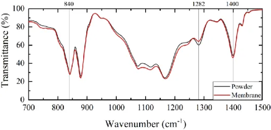
Fourier Transformed Infrared Spectroscopy was used to distinguish the different crystalline phases. The α-phase bands are easily detected, but some β and γ bands are fairly common to both due to their similar chain conformation. [35], [36] While that may happen to some bands, the bands at 840 cm-1, 1282 cm-1 and 1400 cm-1 are mostly exclusive to the β-phase, yet some doubts may arise in the distinction of β and γ-phases.[37], [38]
The characteristic bands of the β-phase were identified on the sample and are summarized in Figure 9 and Table 3.
Table 3 – Absorption FTIR bands characteristics of β-phase
β
Wavenumber (cm-1)
840 1282 1400
14
To quantify the β-phase content of the P(VDF-co-TrFE) powder and membrane, it is assumed that the FTIR analysis follows the Lambert-Beer law and the calculated absorption coefficients, Kα and Kβ at 766 and 840 cm-1, respectively, which are 𝟔, 𝟏 × 𝟏𝟎𝟒 and 𝟕, 𝟕 × 𝟏𝟎𝟒 cm2mol-1.[39]
The relative fraction, or content, of β-phase is given by:
where Tα and Tβ are the transmittance at 766 and 840 cm-1.
Table 4 – Fraction of β-phase in the P(VDF-co-TrFE) powder and the electrospun membrane
β-phase fraction (%)
Powder 81,10
Membrane 79,57
It is possible to observe that all both exhibit a fraction of β-phase around 80% and that it did not increase with the electrospinning.
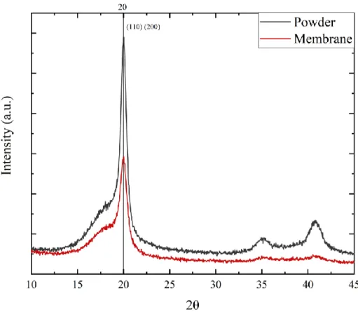
1.2.2. XRD - X-Ray Diffraction
Another way of identifying the different phases of the polymer is using X-ray Diffraction. With XRD it is possible to identify characteristic peaks to every crystalline arrangement, although some present similar peaks. [37][40][41] All phases α, β, and γ-phases present peaks around 2θ = 18º, but β-phase is the only one to present a very distinguishable peak at 2θ = 20º, that is associated with the (110) and (200) diffraction planes.[37][42]
The diffraction angles and crystalline planes of the β-phase are summarized in Figure 10 and Table 5.
𝐹(𝛽) = (100 − 𝑇𝛽)
15
Table 5 – Diffraction angle and crystal plane of β -phase
2θ Crystalline Plane
β-phase 20º (110) (200)
16
1.2.3. DSC - Differential Scanning Calorimetry
Differential Scanning Calorimetry was used as a complementary technique to FTIR and XRD because although it may indicate what phases are present in the polymer, the results not only depend on the crystalline phases but also on the crystalline defects. Nevertheless, depending on the crystalline phase, the range of temperatures where the melting point of the polymer is located indicates what phases are present. According to Martins et al.[3], the melting temperature should be in a range between 167 ºC and 172 ºC, but in this case the melting temperature is located between 148 ºC and 152 ºC that may be the result of the TrFE addition to PVDF.
In addition, DSC also indicates the curie temperature which is important for phase identification and for the poling process. The ferroelectric β-phase is found bellow the curie temperature, but when heated above that point it transforms into the non-polar α-phase.
The melting and curie temperatures of the P(VDF-co-TrFE) powder and membrane are summa-rized in Figure 11 and Table 6.
Table 6 – Curie and Melting Temperatures of the P(VDF-co-TrFE) membrane
TC (°C) TM (°C)
Powder 108 148
Membrane 119 152
17
2. Electric Contacts
Deposition
2.1.1. Electrospinning
The PEDOT:PSS solution was electrospun on top of the P(VDF-co-TrFE) membrane. The pro-duced PEDOT:PSS membrane had no adhesion to the membrane beneath and this may be because of the natural hydrophobic behaviour of the P(VDF-co-TrFE) polymer and/or the static electricity accu-mulated on the P(VDF-co-TrFE) membrane surface. This membrane also presented no electric conduc-tivity possibly because the PEDOT:PSS nanoparticles were encapsulated inside the PEO polymer dur-ing the electrospinndur-ing process, not allowdur-ing the current to flow.
Figure 12 - Electrospun PEDOT:PSS membrane on top of a P(VDF-co-TrFE) membrane. (a) top; (b)bottom
1cm 1cm
18
2.1.2. Airbrush
Both materials were airbrushed in the same conditions, with a constant airflow, at the same distance and with a mask to produce equal contacts on both sides of the membrane. While the PEDOT:PSS created a thin and shiny membrane on top of the polymeric membrane, the carbon paint created a contact with a matte effect on the surface.
Figure 13 – Airbrushed PEDOT:PSS and carbon paint on P(VDF-co-TrFE) membranes. (a) Membrane airbrushed with PEDOT:PSS and mask; (b) Membrane airbrushed with carbon paint; (c) Sample device
with airbrushed PEDOT:PSS; (d) Sample device with airbrushed carbon paint
1cm 1cm
19
The underside of both membranes were observed through SEM. The membrane with PE-DOT:PSS showed that a layer was created on top of the membrane and did not infiltrate the membrane. The carbon paint infiltrated the membrane, as it can be seen from Figure 14. This problem will probably be minimized by increasing the carbon paint viscosity, preventing its infiltration into the membrane.
2.1.3. Thermal Evaporation
Thermal evaporation of aluminium produced a 100nm contact that was non-conductive, perhaps because of the surface morphology and porosity.
(a) (b)
Figure 14 – SEM images of (a) Underside of P(VDF-co-TrFE) membrane with PEDOT:PSS; (b) Under-side of P(VDF-co-TrFE) membrane with Carbon Paint.
Figure 15 - P(VDF-co-TrFE) membrane with aluminium contact deposited by thermal evaporation 1cm
20
Electric Characterization
As consequence of what has been reported previously, only the airbrushed contacts were electri-cally characterized.
2.2.1. Sheet Resistance
Samples of polymer membranes with airbrushed PEDOT:PSS and carbon paint were prepared by placing copper tape on the contacts and leaving a 1 cm x 1 cm area. These measurements allow the characterization and comparation of the electrode film conductivity of the different materials. Both materials presented a similar behaviour, but the PEDOT:PSS contact had an average lower resistivity, as shown in Table 7.
Table 7 – Measurements of sheet resistance of with PEDOT:PSS and Carbon paint deposited by airbrush on top of electrospun membranes
RS (Ω/□)
Material 1 2 3 Average
PEDOT:PPSS 210 470 439 373
Carbon Paint 468 479 ,283 410
Figure 16 – Electrospun membranes with (a) PEDOT:PSS and (b) Carbon paint deposited by airbrush used to measure the sheet resistance.
1,5 cm 1,5 cm
21
A summarization of the deposition methods and materials characterization is presented on Table 8.
Table 8 - Deposition methods and materials characteristics
3. Electric Measurements
Having in mind the results presented on Table 8, only the airbrushed PEDOT:PSS device exhibits good properties, so from now on only this device will be characterized. The characterization was done before and after poling to inquire if the poling process produces any change in the device properties.
Electroactivity
3.1.1. Cyclic Hysteresis
The hysteresis loop (see Figure 17) present an ellipse form which is an indication of a capacitive behaviour with dc conduction, and is not possible to observe a clear ferroelectric switching.
Deposition Method Sample Aspect Surface
Conductivity
Intra Membrane Conductivity
Electrospinning PEDOT:PSS Bad No No
Airbrush PEDOT:PSS Good Yes No
Carbon Paint Good Yes Short-circuit
Thermal Evaporation Aluminium Good No No
22
3.1.2. Pyroelectric Effect
When a pyroelectric material is heated (dT/dt > 0), the dipoles vibrate because of the thermal variation leading to the loss of a common polar orientation of the dipoles and consequently the reduction in the polarization. This decrease of polarization causes the reduction of free charges bound to the ma-terial’s surface, as shown on Figure 18.[8] If the sample is in an open circuit, the charges remain on the surface and an electric potential is generated between the two electric contacts, but if the sample if short-circuit, the electric current flows through the circuit.
When the material is cooled (dT/dt < 0), the dipoles reacquire their orientation leading to the increase of the polarization level, reverting the electric current flow, and the free charges are attracted back to the surface.
The pyroelectric current (ip) can be calculated as function of the rate of temperature change
(dT/dt) [43]:
𝑖𝑝 = 𝑝𝐴
𝑑𝑇
𝑑𝑡 (Eq. 2)
To characterize the pyroelectric effect the device was submitted to thermal variation in order to evaluate its response. It is possible to assess that before poling, the device presented no significant or related response with the thermal variation. After poling, the device exhibited a response that can be associated with the temperature variation, where the signal is not in phase with the temperature change.
23
The pyroelectric coefficient was calculated from equation 1. The pyroelectric coefficient from the device is much lower than the one presented on the literature − 3,3 nC.K-1.m-2 [43], nevertheless
the sample shown an increase in the pyroelectric activity with the poling process which is an indication of ferroelectric dipole alignment.
Table 9 – Pyroelectric Coefficient
Before Poling After Poling p (nC.K-1.m-2) n.d. 0,16
24
Dielectric
3.2.1. Electric Impedance
From the electric impedance spectra (see Figure 20) it’s possible to observe that the device pre-sents a typical capacitive behaviour (a straight line in log |Z| - log Frequency spectra, and phase close to -90º).
3.2.2. Capacitance
The impedance spectroscopy (see Figure 21) shows that the device has low capacitance (25 pF) and that the poling process increases it (56pF). The loss tangent is below 0,1 before and after poling indicating that energy dissipation is relatively low.
Figure 20 - Dielectric Impedance of electrospun P(VDF-co-TrFE) membrane with airbrushed PE-DOT:PSS contacts before and after poling
Figure 21 - Dielectric Capacitance of electrospun P(VDF-co-TrFE) membrane with airbrushed PE-DOT:PSS contacts before and after poling
25
Both the capacitance and the loss tangent were directly obtained from the spectroscopy. The relative permittivity, or dielectric constant, was calculated by:[44]
𝐶 = 𝜀0𝜀𝑟 𝐴 𝑑 𝜀𝑟 = 𝐶 𝜀0 𝑑 𝐴 (Eq. 3)
Table 10 – Device capacitance characterization (values measured at 10KHz)
𝐶 𝜀𝑟 tan 𝛿
(pF) (º)
Before Poling 25 1,941 0,014
After Poling 56 4,349 0,023
The dielectric constant also increases with the poling process, from 1,941 to 4,349, although when compared to the literature, it’s very low.[3, 43]
26
Conclusion and Future Perspectives
This work had as main objective the production and characterization of electrospun electroactive membranes, produced with P(VDF-co-TrFE), and the study of different materials and deposition meth-ods that act as electric contacts.
The P(VDF-co-TrFE) membranes were easily produced and the production parameters were optimized for the presented conditions. The electrospun membranes presented mechanical properties similar to human skin. This and the polymer biocompatibility give the membrane the possibility of being used for internal and external biomedical applications, such as scaffolds to promote cell growth, biosensors, mechanical sensors, actuators, and energy harvesters [44-48]
Previously submitted reports show that the electrospinning technique improves electroactive properties by increasing the of β-phase fraction and by orientate the crystalline dipoles. Based on this work, the electrospinning process did not show any increase in the β-phase fraction and the dipoles domains were not oriented in the same direction.
From all the deposition methods, only the airbrushing was able to produce conductive electric contacts, and only in the case of PEDOT:PSS was possible to make an energy harvesting device. The electrospinning process produced fibres, but the conductive nanoparticles were probably encapsulated inside the PEO polymer and no electrical conductivity was observed. The thermal evaporation produced an aluminium contact with no conduction.
Although of low magnitude, the polling process applied on the electrospun membranes increased their electroactive properties. The poled membranes display a pyroelectric response associated with the thermal variation, which demonstrate that these membranes, with more development, are a viable solu-tion for energy generasolu-tion, sensorial applicasolu-tions and actuators.
The properties of electrospun membranes, such as being lightweight, with low thickness, flexible, etc. are of high interest, so their further development associated with electroactive polymers and the inclusion of electroactive ceramics particles, to increase energy harvesting properties, is highly im-portant for the future of technology.
27
Bibliography
[1] C. Wan and C. R. Bowen, “Multiscale-structuring of polyvinylidene fluoride for energy harvesting: the impact of molecular-, micro- and macro-structure,” J. Mater. Chem. A, vol. 5, no. 7, pp. 3091–3128, 2017, doi: 10.1039/c6ta09590a.
[2] E. A. Edmonds, U. R. Acharya, E. Bonjour, M. Dyer, M. Eisenberg, and G. Fischer, “Plastics Engineering,” p. 193, 2007, doi: 10.1016/S0950-7051(18)30220-X.
[3] P. Martins, A. C. Lopes, and S. Lanceros-Mendez, “Electroactive phases of poly(vinylidene fluoride): Determination, processing and applications,” Prog. Polym. Sci., vol. 39, no. 4, pp. 683–706, 2014, doi: 10.1016/j.progpolymsci.2013.07.006.
[4] J. Gomes, J. S. Nunes, V. Sencadas, and S. Lanceros-Mendez, “Influence of the β-phase content and degree of crystallinity on the piezo-and ferroelectric properties of poly(vinylidene fluoride),” Smart Mater. Struct., vol. 19, no. 6, 2010, doi: 10.1088/0964-1726/19/6/065010. [5] Z. Cui, N. T. Hassankiadeh, Y. Zhuang, E. Drioli, and Y. M. Lee, “Crystalline polymorphism
in poly(vinylidenefluoride) membranes,” Prog. Polym. Sci., vol. 51, pp. 94–126, 2015, doi: 10.1016/j.progpolymsci.2015.07.007.
[6] Y. Chen, X. Chen, D. Zhou, Q. D. Shen, and W. Hu, “Low-temperature crystallization of P(VDF-TrFE-CFE) studied by Flash DSC,” Polymer (Guildf)., vol. 84, pp. 319–327, 2016, doi: 10.1016/j.polymer.2016.01.003.
[7] N. J. Pinto and W. Serrano, “Composite nanofibers of electroactive polymers prepared via electrospinning,” ECCM 2012 - Compos. Venice, Proc. 15th Eur. Conf. Compos. Mater., no. June 2012, 2012.
[8] S. B. Lang, “Pyroelectricity: From ancient curiosity to modern imaging tool,” Phys. Today, vol. 58, no. 8, pp. 31–36, 2005, doi: 10.1063/1.2062916.
[9] B. D. Li and Y. Xia, “Electrospinning of Nanofibers : Reinventing the Wheel ?**,” no. 14, pp. 1151–1170, 2004, doi: 10.1002/adma.200400719.
[10] B. Y. Xia et al., “One-Dimensional Nanostructures : Synthesis , Characterization , and Applications **,” no. 5, pp. 353–389, 2003.
[11] S. Agarwal, A. Greiner, and J. H. Wendorff, “Progress in Polymer Science Functional materials by electrospinning of polymers,” Prog. Polym. Sci., vol. 38, no. 6, pp. 963–991, 2013, doi: 10.1016/j.progpolymsci.2013.02.001.
[12] P. Q. Franco, C. F. C. João, J. C. Silva, and J. P. Borges, “Electrospun hydroxyapatite fi bers from a simple sol – gel system,” Mater. Lett., vol. 67, no. 1, pp. 233–236, 2012, doi: 10.1016/j.matlet.2011.09.090.
[13] J. Schutte, X. Yuan, S. Dirven, and J. Potgieter, “The opportunity of Electrospinning as a form of Additive Manufacturing in Biotechnology,” pp. 13–15, 2017.
[14] C. Ribeiro, V. Sencadas, J. L. G. Ribelles, and S. Lanceros-Méndez, “Influence of processing conditions on polymorphism and nanofiber morphology of electroactive poly(vinylidene fluoride) electrospun membranes,” Soft Mater., vol. 8, no. 3, pp. 274–287, 2010, doi: 10.1080/1539445X.2010.495630.
[15] J. Zheng, A. He, J. Li, and C. C. Han, “Polymorphism control of poly(vinylidene fluoride) through electrospinning,” Macromol. Rapid Commun., vol. 28, no. 22, pp. 2159–2162, 2007, doi: 10.1002/marc.200700544.
28
[16] V. Sencadas, R. Gregorio, and S. Lanceros-Méndez, “α to β phase transformation and microestructural changes of PVDF films induced by uniaxial stretch,” J. Macromol. Sci. Part B
Phys., vol. 48, no. 3, pp. 514–525, 2009, doi: 10.1080/00222340902837527.
[17] A. Salimi and A. A. Yousefi, “FTIR studies of β-phase crystal formation in stretched PVDF films,” Polym. Test., vol. 22, no. 6, pp. 699–704, 2003, doi: 10.1016/S0142-9418(03)00003-5. [18] G. T. Davis, J. E. McKinney, M. G. Broadhurst, and S. C. Roth, “Electric-field-induced phase
changes in poly(vinylidene fluoride),” J. Appl. Phys., vol. 49, no. 10, pp. 4998–5002, 1978, doi: 10.1063/1.324446.
[19] V. Sencadas, V. M. Moreira, S. Lanceros-Mendéz, A. S. Pouzada, and R. Gregório, “α - To - β transformation on PVDF films obtained by uniaxial stretch,” Mater. Sci. Forum, vol. 514–516, no. PART 2, pp. 872–876, 2006, doi: 10.4028/www.scientific.net/msf.514-516.872.
[20] S. Park, Y. Kwon, M. Sung, B. S. Lee, J. Bae, and W. R. Yu, “Poling-free spinning process of manufacturing piezoelectric yarns for textile applications,” Mater. Des., vol. 179, p. 107889, 2019, doi: 10.1016/j.matdes.2019.107889.
[21] M. F. Lin, J. Xiong, J. Wang, K. Parida, and P. S. Lee, “Core-shell nanofiber mats for tactile pressure sensor and nanogenerator applications,” Nano Energy, vol. 44, no. December 2017, pp. 248–255, 2018, doi: 10.1016/j.nanoen.2017.12.004.
[22] V. F. Cardoso, D. M. Correia, C. Ribeiro, M. M. Fernandes, and S. Lanceros-Méndez, “Fluorinated polymers as smart materials for advanced biomedical applications,” Polymers
(Basel)., vol. 10, no. 2, pp. 1–26, 2018, doi: 10.3390/polym10020161.
[23] C. M. Costa et al., “Mesoporous poly(vinylidene fluoride-co-trifluoroethylene) membranes for lithium-ion battery separators,” Electrochim. Acta, vol. 301, pp. 97–106, 2019, doi: 10.1016/j.electacta.2019.01.178.
[24] R. A. Surmenev et al., “Hybrid lead-free polymer-based nanocomposites with improved piezoelectric response for biomedical energy-harvesting applications: A review,” Nano Energy, vol. 62, no. April, pp. 475–506, 2019, doi: 10.1016/j.nanoen.2019.04.090.
[25] A. Wang et al., “Piezoelectric nanofibrous scaffolds as in vivo energy harvesters for modifying fibroblast alignment and proliferation in wound healing,” Nano Energy, vol. 43, no. October 2017, pp. 63–71, 2018, doi: 10.1016/j.nanoen.2017.11.023.
[26] L. T. Beringer, X. Xu, W. Shih, W. H. Shih, R. Habas, and C. L. Schauer, “An electrospun PVDF-TrFe fiber sensor platform for biological applications,” Sensors Actuators, A Phys., vol. 222, pp. 293–300, 2015, doi: 10.1016/j.sna.2014.11.012.
[27] M. Zaccaria et al., “Electret behavior of electrospun PVdF-based polymers,” Annu. Rep. - Conf.
Electr. Insul. Dielectr. Phenomena, CEIDP, vol. 2016-Decem, pp. 137–140, 2016, doi:
10.1109/CEIDP.2016.7785653.
[28] F. He, M. Sarkar, S. Lau, J. Fan, and L. H. Chan, “Preparation and characterization of porous poly(vinylidene fluoride-trifluoroethylene) copolymer membranes via electrospinning and further hot pressing,” Polym. Test., vol. 30, no. 4, pp. 436–441, 2011, doi: 10.1016/j.polymertesting.2011.03.005.
[29] B. Bessaire et al., “Synthesis of continuous conductive PEDOT: PSS nanofibers by electrospinning: A conformal coating for optoelectronics,” ACS Appl. Mater. Interfaces, vol. 9, no. 1, pp. 950–957, 2017, doi: 10.1021/acsami.6b13453.
[30] O. P. Dimitriev, D. A. Grinko, Y. V. Noskov, N. A. Ogurtsov, and A. A. Pud, “PEDOT:PSS films-Effect of organic solvent additives and annealing on the film conductivity,” Synth. Met., vol. 159, no. 21–22, pp. 2237–2239, 2009, doi: 10.1016/j.synthmet.2009.08.022.
29
nanofiber based ultrahigh-strain sensors with controllable electrical conductivity,” J. Mater.
Chem., vol. 21, no. 47, pp. 18962–18966, 2011, doi: 10.1039/c1jm14491j.
[32] H. Joodaki and M. B. Panzer, “Skin mechanical properties and modeling: A review,” Proc. Inst.
Mech. Eng. Part H J. Eng. Med., vol. 232, no. 4, pp. 323–343, 2018, doi:
10.1177/0954411918759801.
[33] A. J. Gallagher, A. Ní Anniadh, K. Bruyere, M. Otténio, H. Xie, and M. D. Gilchrist, “Dynamic tensile properties of human skin,” 2012 IRCOBI Conf. Proc. - Int. Res. Counc. Biomech. Inj., pp. 494–502, 2012.
[34] K. A and L. A, “Mechanical Behaviour of Skin: A Review,” J. Mater. Sci. Eng., vol. 5, no. 4, 2016, doi: 10.4172/2169-0022.1000254.
[35] T. Boccaccio, A. Bottino, G. Capannelli, and P. Piaggio, “Characterization of PVDF membranes by vibrational spectroscopy,” J. Memb. Sci., vol. 210, no. 2, pp. 315–329, 2002, doi: 10.1016/S0376-7388(02)00407-6.
[36] J. R. Imamura, A. B. Silva, R. Gregorio, “Gamma→beta phase transfor Transformation Induced in Poly(vinylidene fluoride) by Stretching,” 2008, doi: 10.1002/app.
[37] R. Gregorio, “Determination of the α, β, and γ crystalline phases of poly(vinylidene fluoride) films prepared at different conditions,” J. Appl. Polym. Sci., vol. 100, no. 4, pp. 3272–3279, 2006, doi: 10.1002/app.23137.
[38] S. Lanceros-Méndez, J. F. Mano, A. M. Costa, and V. H. Schmidt, “FTIR and DSC studies of mechanically deformed β-PVDF films,” J. Macromol. Sci. - Phys., vol. 40 B, no. 3–4, pp. 517– 527, 2001, doi: 10.1081/MB-100106174.
[39] R. Gregorio, and M. Cestari, “Effect of crystallization temperature on the crystalline phase content and morphology of poly(vinylidene fluoride),” J. Polym. Sci. Part B Polym. Phys., vol. 32, no. 5, pp. 859–870, 1994, doi: 10.1002/polb.1994.090320509.
[40] L. He, J. Sun, X. Wang, C. Wang, R. Song, and Y. Hao, “Facile and effective promotion of β crystalline phase in poly(vinylidene fluoride) via the incorporation of imidazolium ionic liquids,” Polym. Int., vol. 62, no. 4, pp. 638–646, 2013, doi: 10.1002/pi.4339.
[41] L. Priya and J. P. Jog, “Intercalated Poly ( vinylidene fluoride )/ Clay Nanocomposites :,” no. May 2002, pp. 31–38, 2003.
[42] E. DM and L. BJ, “Phase transformation to beta-poly(vinylidenefluoride) by milling,” J. Polym.
Sci. Part B, pp. 91–97, 2003.
[43] R. W. Whatmore and R. Watton, “Pyroelectric Ceramics and Films for IR Sensors,” Encycl.
Mater. Sci. Technol., pp. 7924–7932, 2001, doi: 10.1016/b0-08-043152-6/01427-3.
[44] V. M. Radivojević, S. Rupčić, M. Srnović, and G. Benšić, “Measuring the dielectric constant of paper using a parallel plate capacitor,” Int. J. Electr. Comput. Eng. Syst., vol. 9, no. 1, pp. 1–10, 2018, doi: 10.32985/ijeces.9.1.1.
[45] A. N. Arshad, M. H. M. Wahid, M. Rusop, W. H. A. Majid, R. H. Y. Subban, and M. D. Rozana, “Dielectric and structural properties of poly(vinylidene fluoride) (PVDF) and poly(vinylidene fluoride-trifluoroethylene) (PVDF-TrFE) filled with magnesium oxide nanofillers,” J.
Nanomater., vol. 2019, 2019, doi: 10.1155/2019/5961563.
[46] H. I. Virus, A. N. Disorders, C. Report, M. C. Author, and A. C. Author, “ce pte d M an us cri Ac ce pte d M us pt,” pp. 1–46, 2012.
[47] R. Costa et al., “Osteoblast, fibroblast and in vivo biological response to poly(vinylidene fluoride) based composite materials,” J. Mater. Sci. Mater. Med., vol. 24, no. 2, pp. 395–403, 2013, doi: 10.1007/s10856-012-4808-y.
30
[48] B. J. Hansen, Y. Liu, R. Yang, and Z. L. Wang, “Hybrid nanogenerator for concurrently harvesting biomechanical and biochemical energy,” ACS Nano, vol. 4, no. 7, pp. 3647–3652, 2010, doi: 10.1021/nn100845b.
[49] C. Ribeiro et al., “Enhanced proliferation of pre-osteoblastic cells by dynamic piezoelectric stimulation,” RSC Adv., vol. 2, no. 30, pp. 11504–11509, 2012, doi: 10.1039/c2ra21841k. [50] C. Ribeiro et al., “Fibronectin adsorption and cell response on electroactive poly(vinylidene
31
Additional information
32
![Table 1 – Relative permittivity and piezoelectric coefficients of different polymers and ceramics (adapted from [1])](https://thumb-eu.123doks.com/thumbv2/123dok_br/15588227.1050253/23.892.244.661.175.524/relative-permittivity-piezoelectric-coefficients-different-polymers-ceramics-adapted.webp)
![Figure 1 - PVDF α, β and γ phases structures [3]](https://thumb-eu.123doks.com/thumbv2/123dok_br/15588227.1050253/24.892.225.657.134.367/figure-pvdf-α-β-γ-phases-structures.webp)