UNIVERSIDADE DE LISBOA FACULDADE DE CI ˆENCIAS DEPARTAMENTO DE F´ISICA
Towards the development of an automatic
maxillary expansion appliance
Joana Margarida Rodrigues da Silva Dias
Mestrado Integrado em Engenharia Biom´edica e Biof´ısica Perfil de Engenharia Cl´ınica e Instrumentac¸˜ao M´edica
Dissertac¸˜ao orientada por:
To my grandmother Etelvina and to my uncle Carlos, who saw the beginning of this academic journey, but won’t witness its ending.
Acknowledgements
Everyone I want to acknowledge is Portuguese, so all the acknowledgements are written in my native language.
Gostaria de agradecer, primeiramente, aos meus orientadores. Ao Dr. Germano Veiga pela oportunidade de realizar este projeto no Centro de Rob´otica do INESC TEC e por toda a orientac¸˜ao, motivac¸˜ao e ajuda prestada ao longo do decorrer do mesmo. Ao Prof. Hugo Ferreira que sempre se disponibilizou para esclarecer qualquer d´uvida que surgisse.
Agradec¸o tamb´em ao Prof. Francisco do Vale e Prof. Francisco Caramelo pelo apoio e sugest˜oes dadas, `a Dra. Anabela, do laborat´orio do Departamento de Medicina Dent´aria da Universidade de Coimbra, e ao Sr. Jos´e Carlos por toda a paciˆencia e ajuda durante a preparac¸˜ao dos testes.
`
A Mariana Rodrigues, ao Carlo Cadete e ao Jo˜ao S´a por terem colaborado neste projeto, mesmo sabendo que n˜ao seria f´acil.
Ao Jo˜ao Silva que j´a tinha trabalhado neste projeto e me passou conhecimentos necess´arios para continuar o mesmo. `As pessoas da sala I-110, I-109 e I-108 pela ajuda prestada sempre que precisei.
Aos meus amigos que me acompanharam ao longo destes 5 anos, sem eles n˜ao teria sido poss´ıvel completar este curso. Em especial ao Miguel Garcia, `a Joana Capacete, `a Ana Rita Lopes, `a Inˆes Cruz, `a Rochelle Silva, ao Andr´e Gonc¸alves, `a Daniela Freitas, ao Jo˜ao Mendes e, por ´ultimo, mas n˜ao menos importante, ao Fernando S´a.
Por fim, quero agradecer especialmente aos meus pais, av´os e irm˜a, por toda a paciˆencia, compreens˜ao e motivac¸˜ao que me deram ao longo de todo o meu percurso acad´emico e por sempre acreditarem nas minhas capacidades.
Resumo
A expans˜ao do maxilar superior consiste na abertura da sutura palatina mediana, separando os dois ossos que o constituem, com o objetivo final de aumentar a dimens˜ao transversal do maxilar. Este tipo de tratamento ´e realizado maioritariamente quando o maxilar superior ´e mais estreito que o inferior, n˜ao proporcionando o devido encaixe entre os mesmos.
A expans˜ao ´e realizada atrav´es da utilizac¸˜ao de aparelhos que proporcionam a aplicac¸˜ao de forc¸as transversais `a linha da sutura, levando `a abertura da mesma. Atualmente, diversos tipos de aparelhos podem ser utilizados para o mesmo fim, mas um dos mais utilizados entre os m´edicos dentistas ´e o aparelho cuja expans˜ao ´e feita atrav´es da rotac¸˜ao manual de um parafuso de expans˜ao. Sempre que o parafuso ´e rodado existe um pico de forc¸a aplicada, cuja magnitude vai diminuindo ao longo tempo, mas que aumenta assim que o parafuso ´e rodado outra vez. Deste modo, quanto maior a frequˆencia de ativac¸˜ao do aparelho, maior a forc¸a gerada em menos tempo. Assim sendo, com este tipo de aparelhos ´e poss´ıvel realizar quer uma expans˜ao lenta ou r´apida, controlando ent˜ao a frequˆencia de ativac¸˜ao. Contudo, as ativac¸˜oes manuais dos aparelhos trazem algumas desvantagens, uma vez que estes aparelhos s˜ao mais utilizados por crianc¸as que n˜ao tˆem responsabilidade suficiente para realiz´a-las, ficando este processo ao cargo dos pais. Para al´em disso, quando as ativac¸˜oes s˜ao mais frequentes, o aparelho gera forc¸as de elevada magnitude (podendo chegar ao 100 N), o que causa alguma dor e desconforto ao utilizador.
Desde a criac¸˜ao do primeiro aparelho com parafuso de expans˜ao, em meados do s´eculo XIX, este tipo de aparelhos n˜ao sofreu uma evoluc¸˜ao significativa, principalmente no que diz respeito ao m´etodo de ativac¸˜ao, uma vez que continuam a ser meramente mecˆanicos. Portanto, com este trabalho pretendeu-se dar in´ıcio ao desenvolvimento de um aparelho de expans˜ao maxilar autom´atico, que retire partido das novas tecnologias existentes hoje em dia, deixando de requerer ativac¸˜oes manuais por parte do utilizador. Para al´em disso, sendo que as ativac¸˜oes s˜ao autom´aticas ´e poss´ıvel aumentar a frequˆencia de ativac¸˜ao, tornando a aplicac¸˜ao de forc¸as mais cont´ınua. Deste modo, a utilizac¸˜ao do aparelho torna-se mais confort´avel.
Inicialmente, comec¸ou-se por realizar o desenho do aparelho proposto. A automatizac¸˜ao passa pela utilizac¸˜ao de um microcontrolador que ir´a controlar um micromotor e respetivo atuador para exercer a forc¸a pretendida. Uma vez que n˜ao se disp˜oe de muito espac¸o, os componentes escolhidos possuem
que o meio ambiente e por isso nem todas as pilhas ser˜ao apropriadas. A escolha recaiu sobre as pilhas Zinco-Ar devido `as suas reduzidas dimens˜oes e consider´avel capacidade energ´etica, mas tamb´em por n˜ao possu´ırem constituintes de elevada toxicidade, como o merc´urio, que poderiam por em risco a sa´ude do utilizador. Contudo, estas pilhas necessitam de oxig´enio para que a reac¸˜ao eletroqu´ımica ocorra, pelo que a sua performance depende diretamente da quantidade de oxig´enio dispon´ıvel no meio em que se encontra. Para al´em disso, o seu bom funcionamento tamb´em depende da temperatura e da humidade relativa. Uma vez que se pretende utilizar estas pilhas dentro da boca, onde a quantidade de oxig´enio pode variar e a humidade relativa ´e elevada, ´e necess´ario testar o seu funcionamento sob essas condic¸˜oes.
Num estudo anterior, as pilhas Zinco-Ar j´a haviam sido testadas de forma a estudar a viabilidade de serem utilizadas em aparelhos m´edicos intraorais. A performance das pilhas fora estudada num ambiente intraoral artificial, atrav´es da utilizac¸˜ao de saliva artificial. As pilhas, devidamente isoladas com um inv´olucro, foram sujeitas a um teste de descarga, ao mesmo tempo que o inv´olucro era submerso na saliva durante 2 segundos a cada 2 minutos. O tempo de descarga da pilha foi, em m´edia, 80 horas, apenas menos 3 horas que o tempo de descarga determinado pelo fabricante das pilhas, considerando as mesmas correntes de descarga e em condic¸˜oes ambientais mais semelhantes `as do meio ambiente. Tendo em conta estes resultados, conclu´ıram que as pilhas zinco-ar poderiam ser, de facto, uma poss´ıvel soluc¸˜ao energ´etica a utilizar dentro do meio intraoral. Contudo, a fiabilidade destes resultados pode ser posta em causa, uma vez que s´o foi simulada a produc¸˜ao de saliva, n˜ao tendo sido em conta a temperatura e as condic¸˜oes do meio. Assim sendo, este projeto teve como objetivo testar a performance das pilhas num meio intraoral real.
Os testes foram divididos em duas partes. A primeira tinha como objetivo a an´alise do perfil de descarga de uma pilha quando sujeita a determinadas condic¸˜oes de descarga e a segunda tinha como objetivo analisar a capacidade das pilhas alimentarem o aparelho de expans˜ao maxilar autom´atico, fazendo uma aproximac¸˜ao do consumo do aparelho durante um tratamento.
Para realizar os testes dentro do meio intraoral foi necess´ario desenvolver primeiro um dispositivo para testes. Esta etapa incluiu o desenho dos circuitos eletr´onicos dos dois tipos de teste e o desenho do inv´olucro para isolar a eletr´onica do ambiente intraoral, n˜ao esquecendo as entradas de ar necess´arias para as pilhas funcionarem. Estas entradas foram cobertas por membrana de Teflon de forma a evitar a entrada de saliva para dentro do inv´olucro sem comprometer a passagem de ar. Para ser poss´ıvel colocar o inv´olucro na boca, recorreu-se `a fixac¸˜ao do mesmo a um aparelho de contenc¸˜ao remov´ıvel. Antes de realizar os testes, um m´edico dentista realizou o molde da boca dos participantes (4 no total), de forma a criar ent˜ao esse aparelho de contenc¸˜ao.
Com os primeiros testes foi poss´ıvel verificar que as pilhas dentro do ambiente intraoral n˜ao suportam as mesmas correntes quando expostas ao meio ambiente ou `as condic¸˜oes criadas in vitro. Por exemplo quando sujeitas ao mesmo circuito de descarga utilizado nos testes in vitro, a pilha descarrega rapidamente, uma vez que os n´ıveis de humidade relativa reduzem a performance da pilha e o oxig´enio que entra na pilha n˜ao ´e suficiente para suportar os pulsos de corrente. Quando retirada da boca a pilha consegue recuperar a sua tens˜ao rapidamente, o que evidencia a influencia destes dois factores na performance da pilha.
Considerando que as pilhas estavam a ser sujeitas a correntes elevadas, tendo em conta o ambiente intraoral, o circuito de descarga foi alterado de forma a reduzi-las, nomeadamente a corrente de base cont´ınua foi removida, permanencendo apenas os picos de corrente. Com estes novos testes, foi poss´ıvel verificar que nestas novas condic¸˜oes a pilha consegue manter a sua tens˜ao constante, indicando que, de facto, as correntes a que estavam sujeitas anteriormente eram elevadas para o ambiente em quest˜ao e que nestas condic¸˜oes a pilha, entre pulsos, tem tempo para armazenar oxig´enio suficiente de forma a suportar os picos de corrente. Contudo, ao longo dos testes verificaram-se algumas falhas das pilhas, nomeadamente durante a altura em que os sujeitos a realizar os testes estavam a dormir. Esta falha era acompanhada pela recuperac¸˜ao da tens˜ao das pilhas quando os sujeitos acordavam. Inicialmente, considerou-se que o problema estaria na posic¸˜ao das entradas de ar do inv´olucro utilizado, uma vez que estas eram facilmente tapadas pela l´ıngua, impedindo a entrada de oxig´enio na boca. Por´em, depois de se fazerem alterac¸˜oes ao inv´olucro, o mesmo problema persistia, indicando que a falha existente poder´a estar relacionada com a respirac¸˜ao do sujeito durante o sono. Por fim, realizou-se um teste em que as pilhas foram sujeitas a correntes que simulavam o consumo do motor juntamente com o microcontrolador. As pilhas conseguiram manter a sua tens˜ao constante, mesmo com pulsos de corrente mais elavada e com maior durac¸˜ao.
Em suma, este estudo demonstra que as Zinco-Ar tˆem potencial para serem utilizadas no meio intraoral tendo em conta os consumos do aparelho, apesar de serem necess´arios mais testes.
Abstract
Nowadays, the maxillary expansion appliances with expansion screws still require manual activations. In this project work, an automatic maxillary expansion appliance is proposed. The appliance comprises a microcontroller controlling the activation of a micro motor and its actuator. In order to power these components, an adequate and efficient power source for the intraoral environment is necessary, specifically a non-toxic battery with small dimensions and a good capacity. The Zinc-air cells fit these features and have already been successfully tested in vitro through the use of artificial saliva. However, since the intraoral environment is difficult to model, those results might not be reliable. Thus, in this study we intend to test the Zinc-air (Zn-A) cells in vivo, that is, inside real mouths.
The tests had two main goals. The first one was to evaluate the Zn-A cells performance inside the intraoral environment and the second was to test the capability of the cells to power an automatic maxillary expansion device considering its power consumption during the treatment. Before performing the tests, we developed a test device suitable for the intraoral environment, including the electronic circuits and a casing with entrances of air covered with a Teflon membrane to allow the air to reach the cells. To place the casing inside the mouth, we decided to fix it to a removable mouthguard. The mouthguards were created through the cast of the participants’ teeth and palate with the help of a dentist.
The results from the first tests showed that the high levels of Relative Humidity (RH) and the slow oxygen diffusion have a great influence on the performance of the cells. The limiting current of the cell is lower in the intraoral environment than in the outside, and consequently, the cells can not handle pulse loads as well. Besides that, it was observed that when the cells were removed from the intraoral environment, their voltage recovered rapidly, evidencing the influence of those two cited variables. Nonetheless, when the average load current of the discharge circuit was decreased, the cells were able to maintain their voltage constant during an undetermined time. When considering the current consumptions of the automatic device, which involved higher pulse currents with a longer duration, the cells were also able to support those currents. Thus, this study supports the use of Zn-A cells in the intraoral environment.
The limitation of this study was a problem detected during sleep, that is, in the majority of the tests, the cells failed when the subject was asleep, only recovering after waking up. This observation doesn’t invalidate the use of the cells in the intraoral environment, but more studies must be done.
Contents
Acknowledgements iii Resumo v Abstract ix 1 Introduction 1 1.1 Motivation . . . 1 1.2 Objectives . . . 2 1.3 Contributions . . . 2 1.4 Thesis Outline . . . 3 2 Maxillary Expansion 5 2.1 Maxillary bone . . . 52.2 Maxillary expansion treatment . . . 7
2.2.1 Timing of treatment . . . 7
2.2.2 Biological response to the expansion . . . 9
2.2.3 Types of treatment . . . 9
2.3 Maxillary expansion appliances . . . 10
3.2 Proposal . . . 18 3.2.1 Motor (1) . . . 20 3.2.2 Microelectronics (4) . . . 21 3.2.3 Battery (4) . . . 23 3.3 Power Source . . . 23 3.3.1 Zinc-Air Cells . . . 25
3.3.2 Zinc-air cells in an intraoral environment . . . 28
4 Test Device Development 31 4.1 Electronic Circuit . . . 31 4.1.1 Circuit 1 . . . 31 4.1.2 Circuit 2 . . . 35 4.2 Casing . . . 38 4.3 Device assembly . . . 40 5 in vivo Tests 43 5.1 Zinc-Air Cells Performance Tests . . . 43
5.1.1 Test I . . . 43 5.1.2 Test II . . . 45 5.1.3 Test III . . . 46 5.1.4 Test IV . . . 47 5.1.5 Test V . . . 49 5.1.6 Test VI . . . 50 5.1.7 Test VII . . . 52 5.1.8 Test VIII . . . 53 5.2 Simulation Test . . . 55
5.2.1 Materials and Methods . . . 55
5.2.2 Results . . . 55
5.2.3 Discussion . . . 56
5.3 Overall Discussion . . . 56
6 Conclusions and Future Work 59
6.1 Conclusion . . . 59 6.2 Future Work . . . 60
Bibliography 61
A Other Results 67
A.1 Performing Test I outside the intraoral environment . . . 67 A.2 Testing the oxygen reservoir of the Zn-A cell . . . 68
List of Figures
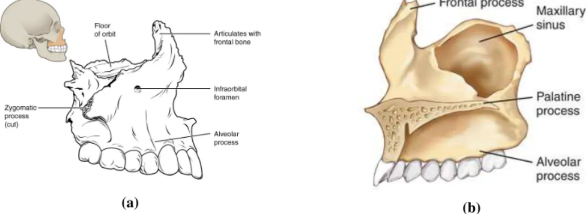
2.1 Maxillary bone. (a) Location of the bone and close-up lateral view. (b) Medial view. . . 5
2.2 Upper jaw (green). ([7]) . . . 6
2.3 Roof of the mouth (palate) and identification of the upper teeth ([8]) . . . 6
2.4 (a) Unilateral ([11]) and (b) Bilateral ([12]) Posterior Crossbites . . . 7
2.5 Appliance used in [4] . . . 7
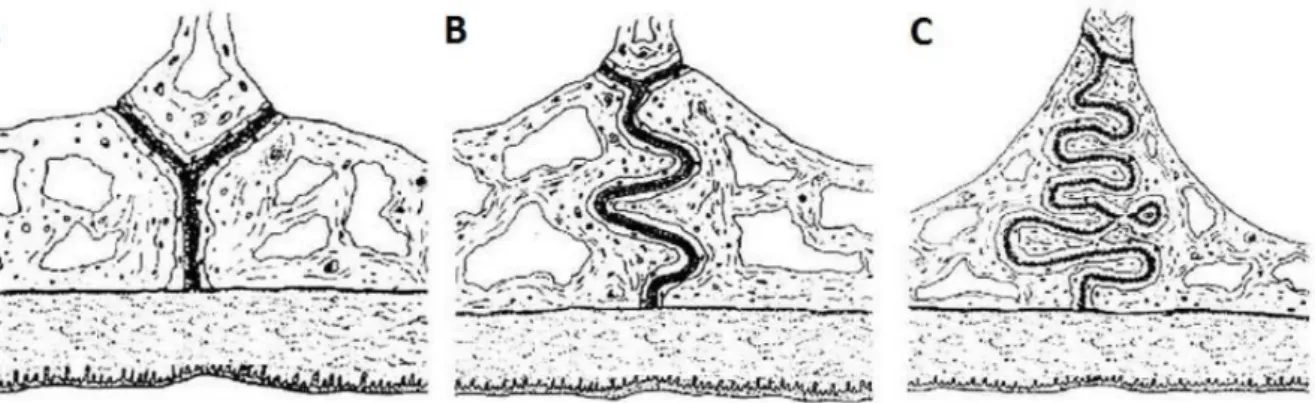
2.6 Illustration of different stage of the maturation process of the median palatine suture. (A) infantile period (B) juvenile period (C) adolescence period. Adapted from [16] . . . 8
2.7 Illustration of the opening of the suture during a maxillary expansion. The white part illustrates the initial position of the teeth and the gray the final. . . 8
2.8 Spring-type appliance. . . 10
2.9 Applied force throughout the expansion with a spring-type appliance [3] . . . 10
2.10 Applied force throughout the expansion with a magnetic appliance [3] . . . 11
2.11 Shape memory alloy appliance composed by nickel-titanium [3] . . . 11
2.12 Illustration of a screw-type appliance being activated with a specific key [30] . . . 11
2.13 Applied force by a screw-type appliance throughout the expansion. (a) Applied force by a screw-type appliance over the time. (b) Expansion provided by a screw-type appliance over the time. [3] . . . 12
2.14 Appliance used in [31] . . . 13
2.15 Hyrax appliance [34] . . . 14
3.3 Automatic maxillary expansion appliance design. (A) Top section view (appliance expanded) 1. Micromotor (0308B Faulhaber) 2. Gearhead (03A) 3. Micro gears 4. Microelectronics (PCB) 5. Screw 6. Cylindrical nut 7. Battery 8. Spring to fix battery 9. Casing. (B) Top section view (appliance closed). The blue arrows indicate the region
where the wires can be placed to anchor the appliance to the teeth (C) Isometric view. . . 19
3.4 0308B micromotor from Faulhaber [47] . . . 20
3.5 Mechanism of a brushless motor. . . 21
3.6 0308B micromotor from Faulhaber with its linear actuator [47] . . . 21
3.7 MSP430G2553 - 32-pin version [51] . . . 23
3.8 Energy density comparison between different types of primary batteries [60] . . . 24
3.9 Zinc-air cell components. Adapted from [65] . . . 26
3.10 Temperature effect on Zn-A cells [60] . . . 27
3.11 Relative Humidity effect on Zn-A cells (at +21ºC) [60] . . . 28
3.12 Discharge profile of Zn-A cells inside the holder in ambient environmental conditions (black) and in the presence of saliva (blue). Adapted from [5] . . . 29
4.1 Schematic of the electronic circuit for Test 1. Highlighted with red is the part correspondent to the discharge circuit of the cell. . . 32
4.2 PCB of the circuit in Figure 4.1 including the components and connectors needed to program the microcontroller and its comparison with a 20cents coin. . . 33
4.3 Configuration of the battery to power the microcontroller and its dimensions (in mm). . . 33
4.4 Voltage at the terminals of 2 Zn-A cells, in series, in series with a resistor. The transition in the voltage represents the instant when the voltage at the cell’s terminals started to be measured. . . 34
4.5 PCB integrated with the Zn-A cells. . . 34
4.6 Schematic of the electronic circuit for Test 2. . . 36
4.7 PCB of the circuit in Figure 4.6 including the components and connectors needed to program the microcontroller and its comparison with a 20 cents coin. . . 37
4.8 CAD model of the casing with the following dimensions: 25 × 17.50 × 10 mm3. . . 39
4.9 3D printed casing. . . 39
4.10 Teflon membrane covering the hole. . . 39
4.11 PTFE membrane. Diameter: 47 mm and Pore size: 0.2µm (Sterlitech Corporation) . . . 40 xvi
4.12 Cast and Acrylic Mouthguard of one of the participants. . . 40
4.13 Example of a final appliance used to perform a test. (a) inferior view: the casing is involved by acrylic resin and covered by teflon membrane (b) superior view: it is possible to see the PLA part (black) of the casing. The PLA has some transparency allows the user to see the LED light. . . 41
4.14 Example of the appliance fixed to one of the participants teeth. . . 41
5.1 Zn-A cell discharge profile during test I in vivo. (Subject 1) . . . 44
5.2 Casing used for test II. (a) CAD model of the Casing. Dimensions in millimeters. (b) 3D printed model. . . 45
5.3 Zn-A cell discharge profile during test II. The dashed lines indicate the moment when the appliance was removed from the intraoral environment and then placed in the mouth again. (Subject 1) . . . 46
5.4 Zn-A cell discharge profile during test III. (Subject 1) . . . 47
5.5 Zn-A cell’s voltage measured during test IV. (1) and (2) in vivo; (3) outside the mouth. During part (2), the microcontroller wasn’t able to store data. (Subject 1) . . . 48
5.6 Zn-A cell’s voltage measured during test V. The dashed line limits the moment when the microcontroller failed. (Subject 1) . . . 49
5.7 Zn-A cell’s voltage measured during the test of subject 2. . . 50
5.8 Zn-A cell’s voltage measured during the test of subject 3. The dashed line indicates the moment when the battery started to fail. . . 51
5.9 Zn-A cell’s voltage measured during the test of subject 4. . . 51
5.10 Appliance used by subject 3. (a) before the test (b) after the test. . . 51
5.11 Stainless steel casing used for test VI . . . 52
5.12 Zn-A cell’s voltage measured during the test VII. The interval between the dashed line corresponds to the moment when the microcontroller didn’t stored values. (Subject 1) . . 53
5.13 Stainless steel casing used for test VIII. The holes were made anterior and posteriorly. . . 54
5.14 Zn-A cell’s voltage measured during the test VIII. The interval between the dashed line corresponds to the moment when the microcontroller didn’t stored values. (Subject 1) . . 54
A.2 Experiment 2. Zn-A cell’s discharge profile when discharged with a background current
of 2 mA and pulses of 10 mA during 100 ms every 200 ms. . . 68
B.1 Signed Informed Consent 1 . . . 70
B.2 Signed Informed Consent 2 . . . 71
B.3 Signed Informed Consent 3 . . . 72
B.4 Signed Informed Consent 4 . . . 73
List of Tables
2.1 Comparison between rapid and slow maxillary expansion treatments using a screw-type appliance 10 2.2 Short time expansion (right after the expansion) and long time expansion (two or more
years after the retention period) verified in different studies. The expansion value corresponds to the difference between the molar teeth (intermolar distance). . . 14 3.1 Specifications of the motor driver . . . 22 3.2 Batteries used in intraoral medical devices and wireless systems (including some prototypes) 24 3.3 Zinc-air cells specifications . . . 25 4.1 Number of times that the LED blinks accordingly to the voltage of the Zn-A cell measure
during the test 1. . . 35 4.2 Specifications of the motor (0308B Faulhaber) . . . 35 4.3 Number of times the LED blinks accordingly to the voltage of the Zn-A cell measure
Abbreviations
Zn-A Zinc-air
HPT High Power Test
SME Slow Maxillary Expansion RME Rapid Maxillary Expansion ADC Analog-to-Digital Converter RH Relative Humidity
Li-ion Lithium ion
PCB Printed Circuit Board PWM Pulse-Width Modulation
MOSFET Metal Oxide Semiconductor Field Effect Transistor RPM Revolutions Per Minute
PLA Polylactic acid
List of Symbols
O2 Oxygen H2O Water OH− Hydroxide ion Zn Zinc Zn2+ Zinc ion Zn(OH)2 Zinc hydroxide ZnO Zinc oxidee Electron
→ Net forward reaction E0 Standard reduction potential
Chapter 1
Introduction
1.1
Motivation
In the orthodontic branch of dentistry, posterior crossbites are common malocclusions with a prevalence of 7% to 23% [1, 2]. This problem is usually corrected by performing a maxillary expansion, which involves the utilization of an orthodontic expander on the maxillae.
Nowadays, to carry out a maxillary expansion, several appliances with different activation methods can be used. These methods can vary between the use of springs, screws, magnets or other materials, all of which being capable of applying sufficient force to provide the maxillary expansion, but with different magnitudes which lead to different treatment durations [3]. From the diversity of appliances, the most used and the ones which can provide a faster treatment have a screw-type activation. The screw is activated by turning a key, which will allow the expansion of the appliance, thus opening the suture and separating the bones. After a few weeks, this will result in the desired maxillary expansion.
The first use of the appliance with an expander screw was in the mid-19th century [4]. Since then, this type of appliance has not been improved significantly, staying merely mechanic and depending on a manual activation to perform the expansion. This latter feature is one of the major disadvantages of the appliance. Moreover, due to the mechanical nature of the expander, there is the need to go to the dentist more often to make some adjustments or to replace some of its parts.
Therefore, it is necessary to design a new device which removes the need for a manual activation and that exploits the new existent technologies, namely related to mechanics and electronics. Nowadays, we have already motors of small dimensions, in the millimeter-order, denominated by micro motors. Thus, the use of this motor, along with a microcontroller, controlling its activation, makes it possible to develop an automatic maxillary expander.
CHAPTER 1. INTRODUCTION
1.2
Objectives
The principal goal of this thesis is to work towards the development of an automatic maxillary expansion appliance. This appliance will be comprising a microcontroller and a micro motor, which will allow the automatic activation of the device by being controlled by the first one.
Before designing and prototyping the appliance is necessary to study the best energetic solution, that is, an appropriate battery to power the components since the device will not function as desired without an efficient solution. In this case, the battery constitutes a problem, because the intraoral environment conditions differ from the ones in which the batteries are designed for, that is, the ambient environment. In addition, the battery has to be small due to the limited space inside the mouth. Thus, the major focus of this thesis is going to be the selection and testing of an adequate battery for the intraoral environment in order to power an automatic maxillary expansion appliance.
Some couple of years ago, Amaral et al. [5] have studied the viability of using Zinc-air (Zn-A) cells in intraoral devices, testing them in an artificial intraoral environment. Their results have shown that using these cells in that environment is an adequate solution.
Although the results pointed to the possibility of using the Zn-A cells in an intraoral device, these cells were not tested in a real environment. Therefore, the primary goal of this project work is to continue the study started in [5] by testing the Zn-A cells in a real intraoral environment. This way, it is going to be possible to conclude whether those cells are in fact an efficient and adequate solution to power the electronics of the device, inside a mouth.
Two different experiments are going to be made to achieve this: • Evaluate the performance of a cell in a real intraoral environment.
• Test the capability of the cell to power the automatic maxillary expansion appliance.
A test device needs to be developed to perform these experiments in a real intraoral environment. This device needs a casing capable of partially isolate the cells and the electronics from the oral cavity, to avoid the direct contact between them. After having the test device, the tests are going to be performed with the help of an orthodontist that will be applying the device on the participants’ teeth.
1.3
Contributions
The Zn-A cells were never tested inside a real intraoral environment, so this project work will provide new knowledge about the performance of those cells in vivo. Also, an article was written to be submitted for Journal of Medical Devices from The American Society of Mechanical Engineers.
CHAPTER 1. INTRODUCTION
1.4
Thesis Outline
This thesis is divided into six chapters, this introductory chapter and five more.
The chapter 2 is dedicated to the maxillary expansion. The chapter begins with a brief anatomical introduction of the maxillary bones to understand when the maxillary expansion is needed. Then, the treatment itself is explained, addressing the biology processes behind it. Also, different appliances used to perform the expansion are described, giving particular focus to the one with screw-type activation.
Considering one of the disadvantages of the cited appliance, in chapter 3, an improved device is proposed, specifically an automatic maxillary expansion appliance. Besides the concept, the design of the appliance is proposed, taking into account the expansion mechanism and all the components needed. As explained in the previous section, in this thesis, the power source of the device is going to explored, particularly the use of Zn-A cells. The specifications of these cells and the possibility of using them in an intraoral environment are discussed. Finally, the tests which are going to be performed to evaluate their performance in a real intraoral environment are proposed.
Since the tests are going to be performed inside human mouths, in chapter 4, the device which is going to be used to perform the tests is described, including the electronic circuits which are going to be used, the casing and the final assembly of the used appliance.
Then, in chapter 5, all the tests performed are described and the respective results are presented and discussed.
Chapter 2
Maxillary Expansion
This chapter addresses the concept of maxillary expansion. In the first section (section 2.1), a brief anatomical introduction is made to understand the need of performing such expansion. The second section (section 2.2) is dedicated to the biological response which occurs during the procedure. Lastly, in the third section (section 2.3), different types of appliances are distinguished.
2.1
Maxillary bone
The maxillary bone is a facial bone located between the orbit and mouth cavities, articulated with other bones, either facial bones - such as the nasal, lacrimal, palatine and zygomatic - or cranial bones, such as the frontal, sphenoid and ethmoid. This bone comprises a body, pyramidal in shape, and four processes: the zygomatic, the frontal, the alveolar and the palatine process, which are identified in Figure 2.1.
(a) (b)
CHAPTER 2. MAXILLARY EXPANSION
wall of the nasal cavity through its medial surface, where it articulates with the ethmoid bone. The upper border of this process also articulates with the frontal bone and the anterior border with the nasal.
• The alveolar process, in the inferior surface of the maxilla, has eight cavities, the teeth sockets, responsible for supporting the roots of the superior teeth.
• The palatine process is a horizontal medially directed projection, which has an upper surface forming part of the nasal cavity and an under surface forming part of the roof of the mouth. Two lateral maxillary bones, the maxillae, form the upper jaw, which is represented with green in Figure 2.2, and meet through the palatine processes. Theses processes are joined by a suture named median palatine suture, forming the roof of the mouth (the palate), as shown in Figure 2.3 [6]. The articulation of these two bones also forms the alveolar arch or maxillary arch, where the superior teeth are housed (also seen in Figure 2.3).
Figure 2.2: Upper jaw (green). ([7]) Figure 2.3: Roof of the mouth (palate) and identification of the upper teeth ([8])
The lower jaw, the mandible, also has an alveolar process, forming the mandibular arch, where the inferior teeth are held. Although the maxillary bones are not articulated with the mandible, they are related through the dental arches. In normal conditions of bone growth, the superior dental arch is a bit wider and larger than the inferior one, to provide a proper occlusion when closing the mouth. However, skeletal discrepancies can occur due to deficiencies during bone growth, giving rise to skeletal malocclusions [9]. One example is the transverse maxillary deficiency, which can lead to a posterior crossbite when the upper jaw is narrower than the lower one.
The posterior crossbite is the most common transverse malocclusion with a prevalence of 7% to 23% [1, 2, 10]. When the discrepancy between the jaws is only present in one of the lateral sides of the maxilla, it is named unilateral posterior crossbite (Figure 2.4a). On the other hand, when the discrepancy is present at both lateral sides, it is called bilateral posterior crossbite (Figure 2.4b).
CHAPTER 2. MAXILLARY EXPANSION
(a) (b)
Figure 2.4: (a) Unilateral ([11]) and (b) Bilateral ([12]) Posterior Crossbites
This type of malocclusion can constrict the nasopharyngeal airways, which makes it difficult to breathe through the nose, leading to mouth breathing and causing difficulties associated with mastication. Thus, correcting this condition is not only important on an aesthetic level, but even more in a functional level [13]. The correction of this type of malocclusion passes through the widening of the palate, that is, a maxillary expansion. In the next section, this treatment is described.
2.2
Maxillary expansion treatment
The maxillary expansion consists in increasing the width of the upper jaw by separating the two maxillary bones through the application of forces. The first reference to this kind of treatment was made in 1860 by Angell [4], who introduced the concept of maxillary expansion through the separation of the maxillary bones using a screw-type maxillary expansion appliance. This appliance, illustrated in Figure 2.5, was fixed to the superior teeth and was capable of applying sufficient forces to expand the palate. The expansion was verified by the appearance of a diastema1between the upper central incisors after two weeks of treatment.
Figure 2.5: Appliance used in [4]
Because the underlying processes and its consequences were not known at the time, this expansion generated some skepticism. However, with the increase of knowledge about this treatment, more dentists supported this technique and nowadays is a common procedure to correct transverse maxillary deficiencies and other conditions, such as upper teeth crowding.
CHAPTER 2. MAXILLARY EXPANSION
which joins the bones through connective tissue, suffers some morphological changes during the cranial and facial growth [14].
Melsen [15] verified that the suture, during the infantile period, reveals a Y-shape in the frontal section, as illustrated in Figure 2.6A, with the surface of the vomer forming the V-shape. During the juvenile period, the Y-shape of the suture is lost, acquiring a more sinuous course due to the formation of bone spicules on the margins (Figure 2.6B). These bone spicules become more interdigitated during adolescence, creating an interlocked course, as seen in Figure 2.6C. Only later in time, in adulthood, the suture is fused by obliteration of the connective tissue fibers with calcified tissue [15, 16].
Figure 2.6: Illustration of different stage of the maturation process of the median palatine suture. (A) infantile period (B) juvenile period (C) adolescence period. Adapted from [16]
Therefore, the expansion should be performed within the first stages of the maturation, since there is less resistance to the expansion due to the presence of less calcified tissue. This way, the separation of the suture can be achieved by the application of forces transversal to the suture through the use of an appliance attached to the teeth [17]. Also, the applied forces will move the bone, instead of the teeth. The Figure 2.7 illustrates the way that the suture opens due to the application of such forces. Since the resistance to the expansion is lower in the anterior region of the suture, because there are lesser bone structures, the maxillary bones separate with a V-shape. In the end, the expansion creates a diastema at the incisor teeth as observed in [4].
Figure 2.7: Illustration of the opening of the suture during a maxillary expansion. The white part illustrates the initial position of the teeth and the gray the final.
CHAPTER 2. MAXILLARY EXPANSION
As the stage of the maturation of the suture advances, the resistance to maxillary expansion increases. The higher the resistance to the separation of the maxillae, minor changes occur at the skeletal level (orthopedics), increasing the occurrence of dentoalveolar modifications (orthodontics), when using a maxillary expansion appliance [18]. When the application of forces through the appliance is not sufficient to move the bones, it is necessary to perform surgery to cut the bone, denominated osteotomy, to provide the separation and new bone growth [19].
2.2.2 Biological response to the expansion
When sufficiently high forces are applied, that is, forces which exceed the limit needed for sutural resistance, changes in the sutural connective tissue are induced [20]. Moreover, the median palatine suture is a bone growth site, that is, a region where the formation of new bone occurs in response to external stimuli, such as the application of external forces [14, 21, 22]. Thus, new bone growth will occur to fill the suture’s gap created with the separation.
In the first hours, right after the first application of forces, some trauma occurs within the sutural area, leading to disruption of collagen fiber bundles and cell death, such as the death of fibroblasts (fiber-forming cell of the connective tissue, which secrete collagen) [21, 23]. During the next 3 to 4 days, the process of bone formation begins through the pre-existing and undamaged osteoblasts (bone-forming cells) at the suture margins. These cells then form concentric layers of bone along the suture margins. During the following 1 to 2 weeks, the formation of new bone continues, as well as the development of collagen fibers [23]. According to the applied tension, the collagen fibers and cells become aligned transversely across the suture [21].
After completing the desired expansion, bone and suture remodeling occurs until the normal morphology is reached. A retention appliance should be used to promote the conclusion of the bone and suture remodeling in order to avoid the relapse of the expansion. This appliance will also allow the dissipation of residual forces accumulated during the treatment [24].
2.2.3 Types of treatment
If the surgery is not needed, two types of expansion can be performed: Slow Maxillary Expansion (SME) or Rapid Maxillary Expansion (RME). The main characteristics of both treatments are summed up in Table 2.1.
In the SME, the forces involved throughout the treatment are lower than in RME. To achieve the same expansion, the SME treatment will take more time than in the RME.
The higher forces in the RME allow more orthopedic changes, but the process of separating the bones can cause more trauma in the affected tissues than when performing a SME.
CHAPTER 2. MAXILLARY EXPANSION
Table 2.1: Comparison between rapid and slow maxillary expansion treatments using a screw-type appliance
Rapid maxillary expansion Slow maxillary expansion
Applied forces with magnitudes up to 100 N [19, 25] Applied forces with 2 to 20 N of magnitude [19, 25] 1 to 3 weeks of treatment [19, 25] 7 to 15 weeks of treatment [26]
Maximum skeletal movement [20, 27] Produce more orthodontic modifications [27]
Microtrauma may arise [20] Better tissue adaptation [27]
2.3
Maxillary expansion appliances
Different types of appliances are used today to perform the maxillary expansion. Considering their activation method, they can be divided into four categories [3]:
• spring-type appliances: composed by springs. One example can be seen in Figure 2.8.
Figure 2.8: Spring-type appliance.
The spring will be compressed and when applied on maxillae, it will exert an opposite force to that deformation, perpendicular to the line of the median palatine suture. The applied forces may vary between 2.4 and 3.9 N decreasing its magnitude with the displacement, as shown in Figure 2.9. Thus, if the resultant expansion is still not the one desired, the appliance has to be adjusted to provide more expansion [3].
Figure 2.9: Applied force throughout the expansion with a spring-type appliance [3]
CHAPTER 2. MAXILLARY EXPANSION
• magnetic appliances: with incorporated magnets which will apply opposing forces, perpendicular to the line of the median palatine suture, allowing the maxillary expansion [28]. It can generate forces of 2.5 to 5 N, which will also decrease with the expansion, as shown in Figure 2.10 [20].
Figure 2.10: Applied force throughout the expansion with a magnetic appliance [3]
• shape memory alloy appliances: consist of alloys which can be deformed at a temperature lower than its transition temperature. When the temperature is higher than the transition temperature, the alloy returns to its original shape, exerting constant forces that will allow the expansion.
Some of these appliances are composed by nickel-titanium, such as the one represented in Figure 2.11. This material has a transition temperature of 34◦C, adequate for the intraoral environment [29].
Figure 2.11: Shape memory alloy appliance composed by nickel-titanium [3]
• screw-type appliances: comprise an expansion screw, that expands the device when the person rotates it with a specific key, as illustrated in Figure 2.12.
CHAPTER 2. MAXILLARY EXPANSION
to the previous ones. As the screw is rotated, the force increases (magnitude peaks shown in Figure 2.13a). Within the next hours the force decreases, but as the screw is rotated once more the applied force increases again, now with accumulated forces. Thus, a higher frequency of activation, will lead to greater applied forces.
(a) (b)
Figure 2.13: Applied force by a screw-type appliance throughout the expansion. (a) Applied force by a screw-type appliance over the time. (b) Expansion provided by a screw-type appliance over the time. [3]
The first three devices are used when the dentist wants to perform a SME because the appliances can’t produce forces of high magnitude. In the screw-type appliances, the activation of the screw can be controlled. This way, it is possible to perform either a SME or a RME. In the first case, the screw is activated two to three times a week, while, in the second case, the activations increase to two times a day.
Due to its versatility, the screw-type appliance is the most used among dentists. Thus, they will be the focus of this thesis. The next section is dedicated to the evolution of this type of appliances.
2.3.1 Evolution of Screw-type appliances
As referred earlier, the first reference to the concept of maxillary expansion was in [4], where the first screw-type maxillary expansion appliance was introduced. The appliance, illustrated in Figure 2.5, comprised a jackscrew that could be rotated by a specific key to provide the application of forces.
Although the concept of maxillary expansion was introduced through this study, namely the RME, the popularization of this method was done some years after with the studies of Haas [31, 32]. In 1961, Haas [31] improved the appliance proposed in [4]. It consisted of an expansion screw activated by a key as well, but instead of having the appliance only anchored to the teeth, the author suggested a dento-mucosal support, that is besides the dental support, the appliance also had an acrylic plate covering the mucosa of the palate (Figure 2.14). This way, the appliance besides applying force on the teeth, applied force on the bone as well.
CHAPTER 2. MAXILLARY EXPANSION
Figure 2.14: Appliance used in [31]
In [31], the author tested the new appliance in 45 individuals (9 to 18 years old) with maxillary insufficiencies. The treatment consisted of activating the appliance twice a day (each activation: 1/4 turn ≈ 0.2 a 0.25 mm) until reaching the needed expansion. After that, the appliance was retained for 3 months without activations to allow the bone formation at the suture and to avoid relapses. During the expansion, the participants reported some pressure at the alveolar processes and palate. The pressure was higher during the activation of the appliance, then, after some minutes, it was dissipated. Regarding the results of the expansion, after 10 to 14 days the distance between the second/third molar teeth was 5.5 mm, maximum, and 1.5 mm, minimum. The expansion resulted in the separation of the upper central incisors, forming a diastema. Also, some adverse reactions in the soft palate, such as moderate hypertrophy, due to the direct contact between the acrylic plate and the palate.
In 1964, Isaacson and Ingram [24] carried out a study about the forces present when using a Haas-type appliance. Five participants (8 to 15 years old) used this appliance together with a dynamometer to measure the applied forces throughout the expansion. When the appliance was first activated (1/4 turn like in [31]), forces with magnitude from 1.36 to 4.53 kg of force were generated, reaching 10 kg (100 N) of force after 15 days, due to force accumulation. The authors considered that this accumulation is the origin of the pressure felt by the participants all over the face, including the nose. Besides that, the load produced per activation was lower in the younger participants than, the older ones, which indicates that the resistance to expansion is higher as the person grows. Thus, a lower applied force would be sufficient to perform the expansion in the younger.
Posteriorly, the Haas-type appliance was considered as unclean, since the acrylic plate covers the palate making it difficult to clean. Also, sometimes adverse reactions occured in the soft tissue of the palate. Considering this problem, in 1968, Biederman [33] developed an appliance named Hyrax (Hygienic appliance for rapid expansion). The activation method of this device is similar to the one in [31], i.e. it uses an expansion screw, but instead of being dento-mucosal supported, it is only dental supported, as shown in Figure 2.15, which facilitates the cleaning process.
CHAPTER 2. MAXILLARY EXPANSION
Figure 2.15: Hyrax appliance [34]
The concept of this appliance is similar to the Haas-type appliance. Thus, the results obtained by both appliances regarding the increase of the maxilla doesn’t seem to differ significantly [35, 36]. Some values obtained using these appliances are shown in Table 2.2.
Table 2.2: Short time expansion (right after the expansion) and long time expansion (two or more years after the retention period) verified in different studies. The expansion value corresponds to the difference between the molar teeth (intermolar distance).
Expansion type Appliance Short time expansion Long time expansion Reference
Slow Haas 5.3 mm 4.0 mm [25]
Slow Hyrax 4.7 mm 3.6 mm [25]
Rapid Hyrax 8.0 mm 3.6 mm [37]
Rapid Haas 4.4 mm N/A [38]
Over the time, other appliances similar to the Hyrax and Haas-type have emerged, only changing their support. For example, in 1973, Cohen and Silverman [39] constructed an appliance with dental support using acrylic covering the teeth (Figure 2.16). This way, teeth inclination during the expansion process is avoided, which sometimes happens when using the other appliances. In addition, the placement is more simple with this appliance compared to the others [20]. In 1977, Mondro and Litt [40] came up with a better solution to place and to remove the appliance, which involved only the expansion screw and acrylic. In this case, the wires between the expander and the acrylic didn’t exist. The acrylic involved the teeth and was extended to the middle of the palate where the expander was incorporated.
Figure 2.16: Appliance with the Cohen and Silverman design [41]
CHAPTER 2. MAXILLARY EXPANSION
Later, in 2004, Wichelhaus, Geserick and Ball [42] proposed an appliance similar to the Hyrax, but with wires of nickel-titanium instead of stainless steel, to reduce the application of forces with high magnitude. The authors tested the appliance in the Instron universal testing machine and observed that when the appliance was activated six times a day, the magnitude of the force applied was between 12 and 14 N [43].
More recently, in 2011, Halicio˘glu, Kiki and Yavuz [43] tested an appliance with the same characteristics as the one in [42], in five individuals, with a mean age of 12.88 ± 0.76 years old. The treatment consisted in activating the screw with 2/4 turn (0.4 mm) 3 times a day. The mean time of the treatment was 7.52 ± 1.04 days, with a retention period of 6 months. After this time, zero relapses were registered. Thus, the authors considered that this way of combining a rapid expansion (regarding the treatment time) and slow (related to the applied forces) produce similar results compared with the other appliances, but in less time (≈ 1 week).
Nowadays, the Hyrax appliance and its variants are the most used [3]. Although improvements have been made, namely related to the applied forces and the support, these appliances still have a common disadvantage, which is the manual activation of the screw. These appliances demand the user to keep track of the activations performed to follow the recommended treatment. Thus, if the patient forgets to activate the appliance, the results can be compromised. Moreover, the user usually is a child, so the parents have to be in charge of the activation. Therefore, creating an automatic appliance would remove the intervention of the user/parent, facilitating the treatment. The next chapter is dedicated to this type of appliances.
Chapter 3
Automatic Maxillary Expansion Appliance
In this chapter, the concept of an automatic maxillary expansion is introduced (section 3.1). In section 3.2, an automatic maxillary expansion appliance is proposed, giving particular attention to its power source in section 3.3.
3.1
Concept
As the name implies, an automatic maxillary expansion appliance should be able to be expanded automatically, allowing a maxillary expansion without the user intervention. Since the automatic apparatus removes this intervention, the frequency of activation can also be increased, so the applied forces per activation can be decreased, allowing a more comfortable expansion for the user.
At the moment, there aren’t automatic maxillary expansion appliances in the market, but Sharizli et al. [44, 45] have proposed one appliance with such characteristics. The schematic of the appliance proposed by the authors is represented in Figure 3.1. As seen, the Hyrax screw is integrated with a micro motor, micro gear and a microcontroller to transform its activations into automatic. The expander activates the screw through the micro motor, which in turn is controlled by a microcontroller. This way, the user doesn’t need to activate the appliance and with the micro motor it is possible to control the applied forces, in such a way that these can become lighter and more continuous.
CHAPTER 3. AUTOMATIC MAXILLARY EXPANSION APPLIANCE
The authors divided the construction of the prototype in five different phases ([44]):
1. Preliminary design: deciding how to activate the screw without a manual activation and deciding the materials to use, including the micro motor, the micro gear and the microcontroller.
2. Mechanical modifications: changing the Hyrax appliance to incorporate the micro gear.
3. Design of the microcontroller system: design of the Printed Circuit Board (PCB) with the components required to control the expander.
4. System integration: Integration of all components: microcontroller system, micro motor and the modified Hyrax - Figure 3.2.
5. Testing the prototype.
Figure 3.2: Automated rapid maxillary expander [44]
In 2009, the first tests of the prototype were performed in a maxilla model (the one shown in Figure 3.2). The tests consisted of applying forces in one direction (x direction), which resulted in a translation in the same direction. The force applied to the four teeth in which the appliance was anchored (upper first premolar and molar teeth) was measured. Each test had a duration of 5 days in which 10 activations (twice daily) of 90° were performed. Ten tests were carried out with the results showing that the force was constant throughout the days between 0.3 and 0.4 N [45].
3.2
Proposal
Considering the previous study as a proof of concept, we decided to improve the automatic maxillary expansion appliance. The concept is similar, that is, we intend to use a microcontroller and a micro motor with the adequate gear to allow the automatic expansion, but without using the Hyrax screw.
Our proposal comprises an automatic expansible casing which will be anchored to the teeth (tooth-borne) through the use of wires (of stainless steel, for example). The housing can be fixed to four teeth, the two superior premolar and two molars, just as in a Hyrax or Haas appliance (Figure 2.14, Figure 2.15).
CHAPTER 3. AUTOMATIC MAXILLARY EXPANSION APPLIANCE
This way, as the casing starts to expand, the device will apply forces transversely to the line of the suture, which will lead to the desired expansion.
The Figure 3.3 represents our design proposal for the automatic maxillary expansion appliance designed with SolidWorks. The expansible casing comprises two parts which will slide against each other to provide the expansion. This casing will also support the components of the device and isolate them from the intraoral environment.
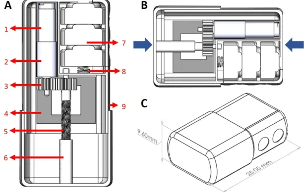
Figure 3.3: Automatic maxillary expansion appliance design. (A) Top section view (appliance expanded) 1. Micromotor (0308B Faulhaber) 2. Gearhead (03A) 3. Micro gears 4. Microelectronics (PCB) 5. Screw 6. Cylindrical nut 7. Battery 8. Spring to fix battery 9. Casing. (B) Top section view (appliance closed). The blue arrows indicate the region where the wires can be placed to anchor the appliance to the teeth (C) Isometric view.
The dimensions of the appliance are 25.05 x 15.84 x 9.60 mm3, which increases to 32.05 x 15.84 x 9.60 mm3when expanded. The linear actuator used here allows an expansion of 7 mm, but this can be increased according to the expansion needed. Moreover, in Figure 3.3B, it is possible to see the region where the wires can be placed to anchor the appliance to the teeth (indicated by blue arrows) and in Figure 3.3C are represented two holes that were designed taking into consideration the performance of the cells selected in section 3.3.
CHAPTER 3. AUTOMATIC MAXILLARY EXPANSION APPLIANCE
[46]. Although there are other metals with greater resistance to corrosion, such as gold or platinum, the costs involved are higher.
In the CAD model, we have a micro motor (1) with its gearhead (2) attached to a micro gear (3). To minimize the dimensions of the appliance, the micro motor is not centered, but we added spur gears to align the linear actuator (5/6) with the center of the appliance. This way, the applied force is well distributed to allow the two parts of the appliance to slide against each other easily. The expansion is possible because the casing of the appliance is composed of two parts. One that houses all the components and the second one with a nut (6) which will be connected to the screw (5) of the linear actuator. When the motor is activated the screw rotates and the nut, which is fixed to the other part of the casing, will move linearly along the screw, providing the expansion.
The microelectronics (4) comprise a PCB with a motor driver and a microcontroller needed to control the motor. The powering of all components is ensured by a battery (7). These components, including the motor as well, will be described in the following subsections.
3.2.1 Motor (1)
The motor is needed to perform the automated expansion. In this case, as we are designing an intraoral medical device, we need to take into consideration the limited space inside the mouth. Thus, a motor with small dimension is required, namely a micro motor. For our application, we are going to use the brushless DC micro motor 0308B from Faulhaber which was previously chosen by the team working on this project. This motor, shown in Figure 3.4, is a 3-phase motor, has a diameter of 3 mm, a length of 8.4 mm and weights 0.31 g.
Figure 3.4: 0308B micromotor from Faulhaber [47]
This motor can be powered by batteries, having a nominal low voltage of 3 Volts, which allow us to avoid high voltages inside the mouth. The brushless motors have permanent magnets which rotate around a fixed armature, as illustrated in Figure 3.5. When electrical current powers a permanent magnet, the motor will move, so no physical commutator (brush) is necessary. An electronic controller can be used to continually switch the phase to the windings to keep the motor turning [48]. This technology increases the reliability and lifetime of the motor since it is less susceptible to mechanical wear [49].
CHAPTER 3. AUTOMATIC MAXILLARY EXPANSION APPLIANCE
Figure 3.5: Mechanism of a brushless motor.
Another advantage of the brushless DC motor is their high torque per weight ratio (sensitivity). The 0308B micromotor can reach a torque of 0.023 mNm (miliNewton meter) at 15000 Revolutions Per Minute (RPM). Adding a linear actuator, with a gearhead of 125:1 reduction ratio, the motor can provide a force up to 2.8 N or 4.2 N in continuous or intermittent mode, respectively. The Figure 3.6 shows the motor with its linear actuator. In this configuration, the maximum diameter is 3.4 mm and the length is 22.85 mm.
Figure 3.6: 0308B micromotor from Faulhaber with its linear actuator [47]
3.2.2 Microelectronics (4)
To control the motor previously described, we need a motor driver and a microcontroller. 3.2.2.1 Motor driver
In order to move the motor, it is necessary to provide power to each phase in a correct sequence. We can program the desired sequence in a microcontroller, but it doesn’t have the necessary current per pin
CHAPTER 3. AUTOMATIC MAXILLARY EXPANSION APPLIANCE
Table 3.1: Specifications of the motor driver
Power Supply Voltage 2 − 5.5 V PWM Input Frequency 1 − 100 kHz Maximum Output Current 750 mA
Max Standby Current 40 µA Max Power Supply Current 10 mA
Dimension 3 × 3 × 0.5 mm
The rotational speed and direction of the motor will be controlled by digital input signals (PWM and DIR, respectively). The speed of the motor can be adjusted by changing the Pulse-Width Modulation (PWM) duty cycle and the rotation depends on the DIR pin state. Another digital input pin, the RP ROG, is used to configure the electro-mechanical coupling coefficient of the motor (”motor constant”) according to the used motor. Through a digital output pin, the FG, it is possible to provide information to an external controller about the speed and phase of the motor.
3.2.2.2 Microcontroller
A microcontroller is an integrated circuit comprising not only a microprocessor but also programmable input/output peripherals, analog-to-digital converter, timers and memory, which allows the information to be read and written in order to store it. One of the microcontrollers’ advantages is their low power consumption (≈ mA) and their ability to enter a sleep/wait mode which allows a consumption even lower (≈ µA). This feature is particularly interesting for our application, since we are designing a battery-driven device and because we will only need to activate the motor for a duration of time, cyclically.
There are several microcontrollers available, such as the ones from Intel®, Atmel, and others. The microcontroller available and selected for this project was the MSP430 from Texas Instrument, which has a 16-Bit central processing unit (CPU). The major advantages of these microcontrollers are the ultra-low-power operating modes and their low costs. In particular, the microcontroller selected was the MSP430G2553 [50], which can be powered with 1.8 to 3.6 V, has a 10-Bit Analog-to-Digital Converter (ADC), a flash memory of 16 KB and RAM of 512 B. During its active mode the consumption is about 230 µA, achieving 0.1 µA in its lowest power mode. Depending on the version of the microcontroller, it can have 16 or 24 programmable input/output peripherals. Its size can also vary, for example, the 32-pin version, represented in Figure 3.7, is the smallest one, having the following dimensions: 5 x 5 x 0.9 mm. In this case, the dimension is a critical feature, so this version would be ideal for the application.
CHAPTER 3. AUTOMATIC MAXILLARY EXPANSION APPLIANCE
Figure 3.7: MSP430G2553 - 32-pin version [51]
Using the timer of the microcontroller, we can configure it to generate automatically a PWM output to control a DC motor. The activation of the motor is programmed to be periodic and with a determined duration. The microcontroller will control the motor through the motor driver using the pins PWM and DIR.
3.2.3 Battery (4)
To power all the electronics, a battery with a voltage similar to the nominal voltage of the components is recommended. Since the appliance is going to be used inside the intraoral environmental, its selection has to be carefully done taking into account:
• its composition, to avoid toxic materials;
• its size and capacity, because we have limited space but still need to have sufficient capacity to power the electronics;
• the environment conditions in which the battery is going to operate (intraoral) since some conditions may influence its performance.
As the power source is such an important component of this appliance, the next section of this chapter is dedicated to it.
3.3
Power Source
A wide variety of medical devices, such as hearing aids, cardiac pacemakers and other implantable devices, is powered by internal batteries [52]. Over the years, these devices have been designed to be smaller and lighter to minimize the user’s discomfort. Since the battery is responsible for occupying a large fraction of the device’s volume, from 25 to 60% [53], the design of smaller devices, inevitably, passes through the selection of batteries with a high volumetric energy density [54]. Usually, the Lithium and Lithium ion (Li-ion) batteries are selected because they have high energy density, both gravimetric (small) and volumetric (light) and a reasonable lifetime [55].
CHAPTER 3. AUTOMATIC MAXILLARY EXPANSION APPLIANCE
shown in Table 3.2, but the possibility of using coin shaped Zn-A cells as batteries for intraoral medical devices was exploited in [5].
Table 3.2: Batteries used in intraoral medical devices and wireless systems (including some prototypes) Device Reference Battery type Dimension Nominal Voltage Typical Capacity
mm3 V mAh Automatic Mandibular Distraction [56] Li-ion (Rechargeable) 21 x 31 x 3.7 3.7 120 Tongue Computer Interface [57] Li-ion (Rechargeable) 11.5 x 18 x 2.8 3.7 20 Intraoral Tongue Drive System [58] Li-ion (Rechargeable) 18 x 24 x 3.5 3.7 110 Arch-Shaped Intraoral
Tongue Drive System [59]
Li-ion
(Rechargeable) 12 x 15 x 5 3.7 50
Although these cells are not rechargeable and have a shorter lifetime than the Lithium ones, considering an automatic maxillary expander, the device doesn’t need a lifetime as high as a pacemaker needs, because the usage is limited to a period of time [60]. Thus, in these cases, it is possible to abdicate from a higher lifetime in order to choose a smaller and lighter battery, since the Zn-A cells have a higher volumetric and gravimetric energy density than the majority of primary (see Figure 3.8) and Li-ion (secondary) batteries. The last ones have an average volumetric and gravimetric energy density of 400 Wh/l and 150 Wh/kg, whereas the Zn-A cells have 1500 Wh/L and 400 Wh/kg, respectively.
Figure 3.8: Energy density comparison between different types of primary batteries [60]
Considering these features of the Zn-A cells, in the following subsections, the characteristics of the Zn-A cells are described and the possibility of using these cells in the intraoral environment is also discussed.
CHAPTER 3. AUTOMATIC MAXILLARY EXPANSION APPLIANCE
3.3.1 Zinc-Air Cells
The Zn-A cells are primary cells which, as the name implies, can provide electrical power through the interaction of the zinc, inside the cell, and the atmospheric oxygen. These cells have been used in some medical devices, namely in hearing aids, and in telemetry devices [60].
Overall characteristics of the Zn-A cell [60–63]:
• Light. Has one of the highest gravimetric energy densities (≈ 400 Wh/kg) compared with other cells (Figure 3.8), making the cell light.
• Small. Has a volumetric energy density of ≈ 1500 Wh/l, because the cell volume is almost filled only by zinc. This feature allows the construction of a cell with small dimensions. In Table 3.3 the dimensions of the coin shaped Zn-A cells are registered, as well as some other specifications.
Table 3.3: Zinc-air cells specifications
Type Model Diameter Height Weight Nominal Voltage Nominal Capacity (ANSI) (mm) (mm) (g) (V) (mAh) 10 7005ZD 5.8 3.6 0.3 1.4 70 a 100* 312 7002ZD 7.9 3.6 0.6 1.4 134 a 180* 13 7000ZD 7.9 5.4 0.9 1.4 260 a 300* 675 7003ZD 11.6 5.4 1.8 1.4 600 a 650*
*Range based on the values of the following manufacturers: Duracell®[60], Rayovac®[60] and Power one [64].
• Discharges with constant voltage. Has a constant internal resistance.
• Long shelf life. With the tab sealing the holes (that is, without entrance of air and other gasses), it loses 2% of its capacity in one year (store at +21◦C).
• Short lifetime. When activated, the constant air exposure and the environmental conditions will discharge the cell, even when in open circuit.
• Limited power output. A higher air disposal, will allow a higher output power, but a shorter lifetime. Thus, it is important to establish a trade-off between the two variables.
CHAPTER 3. AUTOMATIC MAXILLARY EXPANSION APPLIANCE
The Zn-A cell comprises:
• Anode: zinc powder and electrolyte; • Cathode: catalyzed carbon;
• Electrolyte: Potassium hydroxide.
The cathode case has air entrances (identified as air hole in Figure 3.9), which are sealed by a tab. When this tab is removed, the atmospheric oxygen flows into the cell. Then, the oxygen diffuses through a Teflon membrane and comes in contact with the cathode, which reduces it. Afterward, the reduced oxygen interacts with the anode, releasing electrons (Equation 3.1). From the global reaction, theoretically the cell produces 1.65 V, but in practice, this value is approximately 1.4 V [60].
Figure 3.9: Zinc-air cell components. Adapted from [65]
Cathodic Reaction: 1 2O2+ H2O + 2e → 2OH − E0 = 0.40V Anodic Reaction: Zn→ Zn2++ 2e Zn2++ 2OH−→ Zn(OH)2 E0 = 1.25V Zn(OH)2 → ZnO + H2O Overall Reaction: Zn +1 2O2→ ZnO E 0= 1.65V (3.1)
The oxygen consumption is a major factor for the cells’ operating current, being directly proportional. The oxygen transfer rate is dependent on the air holes’ dimensions so larger holes would allow a higher operating current capability. However, due to other gasses transfer, namely water vapor, which has a degradable impact, usually, these holes are small, to balance both transfer rate. Another variable regulating the oxygen and water vapor transfer rates is the porosity of the diffusion membrane, which together with the holes’ size set a maximum continuous-current capability for the cells (limiting current) [60]. Thus,
CHAPTER 3. AUTOMATIC MAXILLARY EXPANSION APPLIANCE
the limiting current is dependent on air availability and the environmental conditions, mainly the relative humidity, which will influence the water vapor transfer rate (more details in the next sections).
The cell discharges with a constant voltage if the average current doesn’t exceed the limiting current even with pulse currents higher than that value. The cell supports these currents because when the load is lower than the limiting current, a reservoir of oxygen builds up within the cell, which allows it to handle higher currents during the pulse. However, the pulses duration must not be too long to avoid oxygen-starvation. In order words, if a single applied pulse has high current and long duration, the electrochemical reaction occurs at a faster rate than the rate at the reservoir of oxygen builds up within the cell; consequently, the cell runs out of oxygen and the voltage declines. Also, if the limiting current is exceeded the cell becomes oxygen-starved and the voltage decreases [60].
3.3.1.1 Effects of environmental conditions
As stated before, the performance of the Zn-A cells depends on the environmental conditions, namely the temperature and humidity levels.
The temperature will influence the performance of the cell as follows: low temperatures reduce the ionic mobility, diminishing the capacity of the cell (Figure 3.10). In addition, the voltage also varies with temperature. Fixing the current, if the temperature is lower than the optimal temperature, the cell’s voltage is going to decrease, as seen in Figure 3.10. The optimal temperature to discharge the cell is between 10 and 40◦C [60].
Figure 3.10: Temperature effect on Zn-A cells [60]
Regarding the humidity, extreme levels (either too high or too low) affect the cell’s performance negatively. Considering a typical electrolyte (potassium hydroxide concentration of 30%), the cell will lose water if the RH is lower than 60% and will accumulate water if it’s higher than 60% (Figure 3.11), decreasing the lifetime of the cell or its power. The loss of water increases the concentration of the electrolyte, making it difficult to maintain the discharge reaction. Also, the gain of water dilutes the
CHAPTER 3. AUTOMATIC MAXILLARY EXPANSION APPLIANCE
Figure 3.11: Relative Humidity effect on Zn-A cells (at +21ºC) [60]
3.3.2 Zinc-air cells in an intraoral environment
The intraoral environmental conditions vary throughout the day mainly due to the secretion of saliva, which can reach 2 liters per day with a higher flow rate in the afternoon than in the morning [66].
The RH varies from 80% to 95% throughout the day, depending on the mouth region [67]. For example, Saraiva et al. [68] verified that the RH is higher in the molar site (RH ≈ 90.8%) than the incisor site (RH ≈ 84.8%). Regarding the temperature’s variation, it also varies throughout the day between 30 and 36◦C [69, 70].
Comparing these values with the optimal values of temperature and RH of the Zn-A cell, the temperature of the intraoral environment is not going to influence the discharge profile. The same doesn’t happen when analyzing the RH of the mouth because it’s much higher than the optimal value. Thus, the water vapor transfer rate will influence the performance of the cell negatively, decreasing its limiting current and the capacity of the cell as described previously.
3.3.2.1 in vitro intraoral environment
In order to preview the discharge profile of the Zn-A cells under an intraoral environment, some in vitrotests were made in [5]. This project work had the goal of studying the feasibility of using these cells in intraoral medical devices. The authors started by analyzing the discharge profile of 312 Zn-A Rayovac®cells performing the HPT:
1. under three different levels of RH: 50, 70 and 90% at 37◦C. The levels of RH and the temperature were controlled by a climatic chamber.
2. at ambient temperature and RH, but placed inside a metallic holder with an air entrance covered by a Teflon membrane.
3. the same as the last one but with the presence of artificial saliva. The holder was submerged in the artificial saliva for 20 seconds every 2 minutes to simulate the intraoral environment and the secretion of saliva.

![Figure 3.2: Automated rapid maxillary expander [44]](https://thumb-eu.123doks.com/thumbv2/123dok_br/15630098.1056030/44.892.212.680.484.681/figure-automated-rapid-maxillary-expander.webp)

![Figure 3.9: Zinc-air cell components. Adapted from [65]](https://thumb-eu.123doks.com/thumbv2/123dok_br/15630098.1056030/52.892.232.656.466.725/figure-zinc-air-cell-components-adapted-from.webp)


