ESTG Cargo 2 Team
IPL - Instituto Politécnico de Leiria
Team nº 24
Author’s: Prof. Nuno Rodrigues
Tiago Nunes Marco Santos António Pires Dinarte Abreu Eduardo Farinha Luís Marques Nuno Gomes Rodolfo Mouta 5th of June, 2009
Table of Contents
1. Executive Summary...2
2. Background...3
3. Problem statement and objectives ...3
4. Aerodynamics ...5
5. Calculation of Payload ...13
6. Wing and Tail Structure ...14
7. Fuselage and Landing Gear ...17
8. Control Systems and Power Trust ...19
9. Materials and Construction...21
10. Possible Design Modifications ...22
11. Project Cost and Planning ...23
12. Team’s Organization and Capabilities ...25
13. Engineering Software ...25
14. References ...27
1. Executive Summary
This report summarizes the project of "ESTG CARGO 2009", an aircraft designed by a student team of Escola Superior de Tecnologia e Gestão, of the Instituto Politécnico de Leiria (ESTG-IPL), for the Air Cargo Challenge (ACC) 2009.
This document describes the main aspects of the design process, including some of the approaches that were chosen by the team to achieve the objectives of the ACC, namely to create a radio controlled (RC) aircraft that will lift the most weight, while meeting a set of specifications. Detailed drawings of the ESTG-IPL Cargo plane will be presented, together with the technical and experimental considerations that justify the most relevant design options.
The main design features of the airplane were defined early in the design process, namely the use of a single high wing aircraft, with a Selig1223 airfoil. Since then, an analysis of the wing's aspect ratio has been made, in order to determine the optimum dimensions of the wing, in terms of the generated lift and drag.
Other considerations have also been taken into account, like the use of an independent cargo bay, with easy weight loading access and the use of and extension harm, that will allow the positioning of the plane's engine in front of the wing, in order to improve the airflow and to move the plane's centre of gravity forward.
Work has also been done regarding the project of the aircraft's structure, in order to keep the plane's weight to a minimum, while supporting the high loads required for a good performance in the competition.
Some of the design decisions described in this report result from the knowledge gathered from the participation of the ESTG-IPL team in previous editions of the ACC. Nevertheless, extensive studies have been developed in order to eliminate some of the observed inefficiencies or to further improve some design options that proved to be successful in the past.
Following a brief background of the team's involvement and the goals of the ACC, this report will address the main technical issues of the ESTG-IPL's aircraft, namely Aerodynamics, Payload Calculation, Materials and Construction, Wing Structure,
Fuselage and Landing Gear, Control Systems and Power and Possible Design Modifications.
Following these technical considerations, some organizational issues, regarding the execution plan, team's budget and team organization will be discussed.
2. Background
The idea of competing in AirCrago Challenge 09 comes, mainly, from the fact that we enjoyed very much our previous participation, in 2007, and from the fact that we were able to gather almost the same team to work in this year’s competition. Certainly that the results obtained in the previous competition gave us motivation for a new participation, but also compelled us to raise the expectations, searching this year better results.
Adding to the ’07 team new and fresh blood, we decided to go through, this time with knowledge that we didn’t have 2 years ago, about the project, building and flight of the airplane.
Since the team is mainly composed by elements that also worked in the previous competition, we were capable to identify the problems as they appear. Right after de ’07 edition, the team gathered together and tried to identify all the problems we came across, in an attempt to avoid them in this year’s competition.
Nevertheless, and because all members continue to study and most of us are now working at the same time, we faced the major restriction of all: availability. From a crew of 9, it was possible to divide the elements according to their expertise, electrical and mechanical, distributing the little time available, always trying to obey the deadlines.
3. Problem statement and objectives
The evaluation of team’s performance is divided into two parts, project and fly, so, to do a good final punctuation it is needed a good individual classification.
In a project the main goal is to elaborate one report to show and justify our options. In the competition’s weekend, we need to defend our project in an oral presentation. It is also mandatory the presentation, in this report, of the chart of Payload Weight versus Density altitude.
In the second part of evaluation, witch is the part of the flight, the main goal is to do a valid flight with the highest possible load, without forgetting the time which we spend loading the plane. The angle of landing is also an evaluation point.
Like the maximum distance of landing is imitated to 60meters, and the horizontal projected area is 0,7m2, the main problem consists in finding the best configuration between drag, lift, wingspan, wing’s chord and weight of the plane. This combination of parameters should give the maximum lift at the end of 60m limit of taking-off. The complete flight must have a taking-off, a complete 360º run and a successful landing in 120m.
With this in mind, the team objectives are:
- Project one airplane, with the maximum horizontal projected area of 0,7m2. - Choose the right dimension of the plane for the best run of take-off in 60meters;
- Consider the use of only one motor, AXI Gold 2820/10, feed of Lipo Battery of 3 Cell in series, ensuring always a consumption of the brushless motor do not exceed 45 Amp;
- Select 3 propellers, with the maximum efficiency possible; - Project a Cargo Bay, with the best accessibility possible;
- Project the entire plane in a way that the cargo bay should be located at centre of gravity;
- It is mandatory the plane fits in a box with 1100x500x400mm;
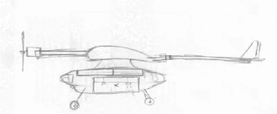
Figure 1 – Main Sketch.
4. Aerodynamics
In an aircraft aerodynamics, the wing represents an extremely important role in the performance. All aspects must be carefully considered in order to achieve the perfect design. The teams look to essential parameters for a wing design such as wing position, airfoil, wingspan, chord and sweep.
The wing should give the stability to the plane, so, with that purpose, the team decided to place the wings on top of the fuselage. This will allow a very stable plane because when the plane is rolling in a flight, the fuselage will force the plane back into its normal position. Another key issue on wings placement is how they are connected with the fuselage. The team thinks that connections should be as minimum as possible, in order to maximize the wing area, and consequently, the plane will produce more lift. The minimum connection area is limited for the structural robustness. The type of wing that the plane will use is called a high wing. This wing will allow a less control’s dependence from load that means the plane has a more roll stability.
Based on team’s previous experience, the airfoil is the same used on last AirCargo Challenge, named SELIG 1223. With this airfoil, the team had a good load on last Challenge, but a quick search in the internet was useful to see that the other teams on competition over the world see this airfoil very interesting for the similar purposes. To validate this, we use the figure 2, where different airfoils are compared. As we can see the SELIG 1223 as the best lift and drag coefficients.
Figure 2 – Comparison between different airfoils[1]
The SELIG 1223, figure 3, is an airfoil designed for higher lift forces than other airfoils, but with an increase in Drag force. For the team, this is not a problem, since the main aim is to lift the maximum load possible.
Figure 3 - SELIG 1223 airfoil
The next step is to choose the wing’s dimension. In this edition, the AirCargo Challenge juries define 0.7m2for the maximum projected area. Based on this rule the Team defined 0.6m2for the wing area.
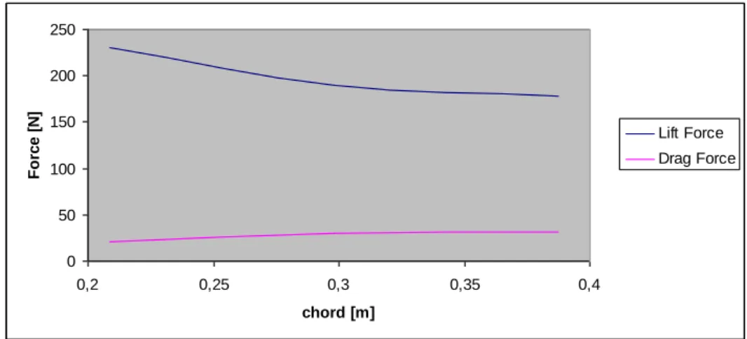
Our initial approach was the usage of Ansys CFX, a software tool, to understand the behavior of different wings, changing the wingspan and the chord. The team was analyzing the draft and lift forces, as we can see in figure 4. With a big chord we have a less lift and more drag.
Figure 4 – Lift and Drag force vs chord
But, in fact, there is another important consideration in wing design, called the aspect ratio of the plane’s wing and defined by equation 1. This is a ratio between wingspan (b) squared to the surface area (S).
2
b Ar
S (eq. 1)
The lift is related with aspect ratio, where higher aspect ratio produces more lift than a plane with lower values for aspect ratio. Despite those kind of plane can’t fly very fast, the speed is not an important parameter for the aim of project, so the purposes of ESTG Cargo 2 is a plane with high aspect ratio. This will implicate a longer wingspan. Our goal is to have an aspect ratio higher than 10, which is a normal value for sailplane. In figure 5 we can see the variation of aspect ratio with different wingspans for a fixed wing area.
Figure 5 – Aspect Ratio for different Wingspan
0 50 100 150 200 250 0,2 0,25 0,3 0,35 0,4 chord [m] Fo rc e [ N ] Lift Force Drag Force 0 5 10 15 20 25 1 1,5 2 2,5 3 3,5 A s pec t R a ti o Wingspan[m]
Observing the chart, we can see that for an aspect ratio higher than 10, we have a minimal wingspan of 2,5m.
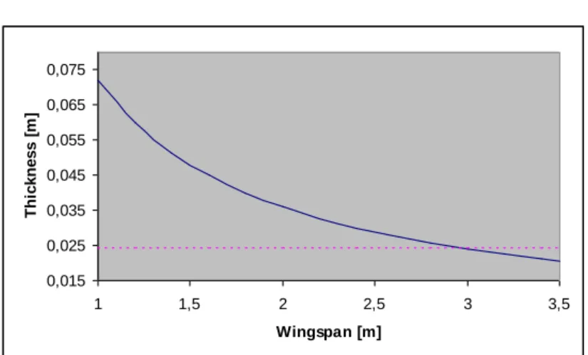
Another point for the selection of wingspan is the thickness of the aerofoil. Based in the team’s idea for wing structure (see chapter Wing Structure and Construction) we need a minimal thickness of 0,024m. In chart seen in figure 6, we can observe that our purpose is archived for a wingspan of 3m. The thickness dimension is near 12% of the chord. The value of chord is calculated from equation 2.
S c
b (eq. 2)
Figure 6 – The thickness of an aerofoil for different wingspans.
Mixing the information from the both charts, we decide for 3m of wingspan. With this we will have a chord of 0,2m.
Based on these values, and using the equation 3, we can calculate that our plane will fly in a Re between 1x10⁵ and 6x10⁵.
Re vc (eq. 3)
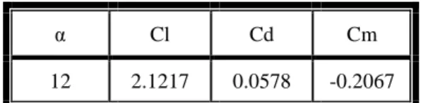
The next step was to calculate the angle of attack. We use JavaFoil, to analyze our airfoil. This is a web application that can give important results about drag, lift, and pressure distribution. As we can see on table 1, the best attack angle is 12º, where we can get the maximum lift coefficient.
0,015 0,025 0,035 0,045 0,055 0,065 0,075 1 1,5 2 2,5 3 3,5 Wingspan [m] Th ic k ne s s [ m ]
Table 1 – Different parameters
α Cl Cd Cm
12 2.1217 0.0578 -0.2067
From Profili 2, another software tool, we get other important information like the chart shown in figure 7. There we can se the variation of relation between drag and lift, for different angles of attack and different Reynolds number.
Figure 7 - Drag coefficient (Cd) vs lift coefficient (Cl).
On figure 8, we can see the pressure coefficient distribution over the airfoil. As we can see, the upper side has higher values than the lower side.
Figure 8 - Pressure Coefficient Distribution
Based on previous values for wing dimensions, we calculate from equation 4 for elliptic chord, equation 5 for Stender chord and equation 6 for the lift force over the wing span, the distribution of lift force over the wing span. The result can be seen at figure 9.
2 4 2 1 e S y c b b (eq. 4) . s e c c c (eq. 5) s L W c bc (eq. 6)
Figure 9 - Lift force over Wing Span.
Last parameter of our wing, is the sweep. Since this aspect has an important role in supersonic planes, as it allows for higher speeds but less lift, the team though this is not important for our plane, since our purpose is to have the maximum lift possible. So, the team kept the wings perpendicular to the fuselage.
Another important part on aircraft aerodynamics design is the tail. The main aim of the tail is to give some stabilization since it holds the rudder, which is used to balance out any yaw created during a rolling manoeuvre. Our aim on the tail design are the properly dimension to ensure the needed stabilization and to minimize the drag, since the tail doesn’t produce any lift.
Several tail planes can be used in an aero model. Some criteria were used to select a tail from different configuration, like conventional, V-tail, T-tail, vertical tail and flying wing. Those criteria are:
o Low Speed Handling: since the airplane is expected to fly at low speed, it must be able to maneuver in a low Reynolds number;
o Environment;
o Weight: the tail plane must be light to maximize potential flight score but must be able to counteract nose-down tendencies;
o Drag efficiencies: drag should be minimized in designs to make a more efficient use of available power and increase speed;
o Ease of fabrication: during flight testing, if any part breaks, repair or reconstruction must not be complex or time-consuming.
0 10 20 30 40 50 60 70 80 0 0,2 0,4 0,6 0,8 1 1,2 1,4 1,6 Wing Span[m] Li ft [N /m ]
We found a very interesting table, where different criteria were used to select one tail. Each criteria, had a punctuation between 1 to 5, where 5 is the best, and 1 is the worst, and for each criteria was given weighting factors. This can be seen at table 2.
Table 2 – Tail selection[4].
Based on this table we choose the conventional tail. The tail is divided in horizontal and vertical tail. Starting with horizontal tail, we used equations 6 to 9 to calculate the chord and wingspan of the tail. In equation 7, we calculate the volume, which is defined as the multiplication of wing area, wing chord and volume coefficient of horizontal tail.
H H
V V S c (eq. 7)
The area of horizontal empennage is given by equation 8, witch is defined by the ratio between de volume of horizontal empennage and distance between gravitational centres of the wing and tail.
' H H H V S l (eq. 8)
For the tail wingspan, we use the equation 9, based on equation 1 of the aspect ratio.
.
H H H
b A S (eq. 9)
The chord is given in equation 10, and is similar to equation 2.
H H H S c b (eq. 10)
For the vertical empennage, we can use the same equations, unless for the volume calculation. For this case, the volume can be calculated as a multiplication of wing area, wingspan and volume coefficient of vertical tail. That is express in equation 11.
V V
V V S b (eq. 11)
So, based on the upper equations, we can resume our results in the next tables. In table 3 we can see the parameters needed for the calculation of tail parameters. In our reference we found the suggestion of 3.5 for the aspect ratio of the horizontal tail, and 1.2 for the vertical tail. For the volume coefficient, on the same reference, they propose 0.3 for horizontal tail, and 0.015 for vertical tail. In table 3, the Omega is a reference for a horizontal tail or vertical tail.
Table 3 – Values of different parameters needed for the calculation of tail parameters
Volume coefficient
Wing
area Chord
Between gravitational centres of the wing and
tail Aspect ratio V S [m2] c [m] l' [m] Ar Horizontal empennage 0.3 - - 1 3.5 Vertical empennage 0.015 - - 1 1.2 Wing - 0.6 0.2 - -
On table 4, we can look the calculated parameters for the both tail parts.
Table 4 – Values of different parameters needed for the calculation of tail parameters.
Volume Wing area Chord Tailspan
V [m3] S [m2] c [m] b [m]
Horizontal
Tail 0.048 0.04 0.1069 0.3741
vertical Tail 0.036 0.03 0.1581 0.1897
We decided, yet, for choosing a NACA 0009SM airfoil for both tails, since this airfoil has lower drag force.
In model planes, the V-n diagram is very important information. For our plane the team considers a structural load factor (n) as 10. Based on equation 12 for the velocity, we have the diagram express in figure 10.
1 2 L W V SC n (eq. 12)
Figure 10 - V-n diagram.
We can see velocity loss, given when n=1, and Vs 11.83 /m s and the maneuver
velocity is VA Vs nmax 37, 40 /m s.
5. Calculation of Payload
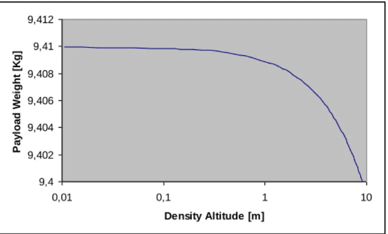
The payload weight is calculated based on equation 14, and the results, depending on the density altitude, are shown in figure 11, with a velocity of 12m/s. This velocity was achieved in ground tests. These tests can be described in section Control Systems and
Power. The payload weight was calculated based on equation 13 and 14. For the density
altitude calculation was used the equation 18. The Equations 15 until 17 were used as auxiliary helps. 2 1 2 L L P F C A V (eq. 13) L plane PL F W (eq. 14) 0 . T T L H (eq. 15) 0 0 . (1 ) qM RL L H P P T (eq. 16) 01000 PM RT (eq. 17) -15 -10 -5 0 5 10 15 0 10 20 30 40 50 60 n Velocity [m/s] CLmax+ limit CLmax- limit Strutural limit Va=37,40 Strutural limit Vs=11,83m/s
0.234969
44.3308 42.2665
Da (eq. 18)
Figure 11 - Payload weight vs. density altitude.
As we saw in figure 11, the plane is able to lift around 9.4kg of load. The linear approximation equation is given in equation 19.
9.41 0.0011
PL Da (eq. 19)
6. Wing and Tail Structure
The wing has a rectangular geometry with a 200mm of chord and a 3m of wingspan. For that chord, the SELIG 1223 airfoil’s thickness is 24mm, witch his project is, by it self, an interesting challenge. Adding to this difficulty, we have the regulations commitment that all planes should be able to be transported in 1100X500X400mm box, witch causes the wing structural design more complex. With a wingspan of 3m and the previous limitation, we were forced to fraction the wing in three segments. So, these three distinct segments must be ready to properly be connected. This can be seen in figure 12. 9,4 9,402 9,404 9,406 9,408 9,41 9,412 0,01 0,1 1 10 Density Altitude [m] P a y loa d W e igh t [K g]
Figure 12 – Wing.
This wing is made by two conical rods, one main and other secondary, and frames ribs. The rods coning shape in the wing segments allow a perfect connection between the outside segment’s root and central segment’s tip. The central segment has a 50mm outside rod spar, to promote the best assembly between those segments. This mean, that the diameter rod in outside segment’s root is larger than the tip rod diameter. This can be seen at figure 13.
Figure 13 – Rod connection.
The ribs are build in sandwich composite made by one layer 0.90º carbon fiber with 120g/m2 and a PVC foam core with a density of 75Kg/m3. One way to low the weight of these ribs is to do a frame structure. As the skin is made by polyester film, the rib’s border is glued to one balsa blade with 10x1mm. This will help the adhesion between the polyester film and ribs.
Figure 14 – Ribs assembly in the spars.
It is in this element that the motor structure, the tail’s rod and the fuselage rib’s connections are assembled. These ribs are made in carbon fiber, since the all the lift is transferred between the fuselage and wings through these components. In figure 15 we can see the connection above referred.
Figure 15 - Cross let.
The tail has a shape of inverted T, based on NACA 0009 airfoil, in order to low the drag. Both vertical and horizontal tail are build by sandwich ribs, identical to wing and balsa’s spar. The leading edge is made by balsa, in order to ensure the best geometry definition. The skin is made by Polyester film.
The elevator and rudder are fixed by a shaft in the end of tails. The tail is supported by a carbon rod, because it’s lower weight. The tail structure can be seen at figure 16.
Figure 16 – Tail structure. All the draws can be seen at Attachment II.
7. Fuselage and Landing Gear
The fuselage is a key element, since inside is the cargo bay. The contact between the fuselage and the wing is done in a minimum connection surface, achieving a bigger wing’s area. Another key aspect is the body shape. We use a neutral airfoil NACA 00018. So, by this way, this shape can reduce the drag.
All the assembly is dismountable and connected to the central wing, through one connection to central rib. This assembly has two pieces, being one of them mobile. This allows a faster and easier accessibility to cargo bay. This fast access is a fundamental aspect, since there is a limit time to put all load’s inside. Another important point is the time of this operation, since less time spent means more points the team. In figure 17 we can see all the assembly.
Figure 17 – Fuselage.
The movable zone of cargo bay works like a drawer, allowing just the longitudinal movement. As we can see in figure 18, the load is placed in this chamber. This space has one rib, done in balsa, involved in a carbon fiber skin. To lock this movable drawer, we will use one pin with a spring. This lock system can be seen at figure 19. The second half of cargo bay was built in carbon fiber with epoxy resin. This carbon skin is fixed to the central rib.
Figure 18 – Mobile Zone
Figura 19 – Lock of movable Zone
The rear landing gear will be assembled with a carbon blade. With this material, the landing gear can have enough flexibility and strength. This landing gear can be built with several carbon blades, allowing the blades to slide, minimizing the risk of delamination failure. This rear landing gear can be seen at figure 20. The front landing gear will be a spring steel lifter. The wheels will be built on PVC.
Figura 20 – Rear Landing Gear. Like the wing, all the drawings can be seen in Attachment II.
8. Control Systems and Power Trust
To ensure the right selection of the propellers that we’ll use in the competition, we decided to run some velocity tests, for different types of propellers, in order to choose the ones that allowed maximum speed at the take-off limit.
Since our new model is yet to be assembled, for security reasons and because the tests we pretended could be run in the ground, we decided to do them with another model without the wing mounted. Nevertheless, we are fully aware that the drag caused by wings is an important contribute in the results. Later, we will repeat these tests with the new model totally assembled.
We measured the velocity evolution by installing a GPS device in the model. This equipment was configured to log the model’s instant speed second by second (minimum available time gap). The records were uploaded to a computer in CSV (Comma Separated Values) format and assessed in spreadsheet software.
We tested many types of propellers, for 2 different loads. Some of the propellers tests were repeated to ensure data consistency due to possible faulting testing conditions, like battery charge variations or GPS precision errors.
Since the regulations tell us that we have a 60m runway take-off limit, we run the tests covering around 100m, obtaining a larger quantity of GPS points, thus allowing to a better understanding of the velocity evolution.
As an example, we show figure 21 that is a result of part of the data processed. The chart relates, for each type of propeller, the model’s speed with the distance covered, for an extra load of 4,5kg. This chart allows us to clearly identify the speed at the 60m take-off limit.
Figure 21 – Different propellers speed.
As we realize even before processing the data, larger propellers allows higher accelerations. This fact is confirmed in the previous chart, showing that the propeller with better performances is the 12x6E.
According to a table from the motor’s manufacturer, and bearing in mind that 12x6E is not the one that shows higher efficiency in electrical to mechanical conversion, it is the one that that allows us to do a better use of the mechanical power (from the group of propellers used in the tests). It is relevant to say that, in this context, the battery autonomy is not a fundamental requirement for the contest, thus, lack of efficiency is not an obstacle. The current limitation of 45A was not exceeded.
All said, 12x6E propeller is, for now, our main propeller, selected to equip our airplane. Nevertheless, we still have the possibility, facing results from new tests, of choosing another type of propeller, possibly with larger diameter (e.g. 13x…).
0 20 40 60 80 100 120 0 10 20 30 40 50 60 Speed Vs Distance Load: 4.5Kg 12x06E 12x08E 12x06C 11x7E 10x7E 10x5E Take-off line Distance [m] Sp e e d [ Km /h ]
Our control system can be seen at figure 22. For that we have different servos, one RF receiver FP-R1480P PCM1024, a battery pack with 3200mAh, an ESC Jeti Model SPIN 66 and a Motor defined by regulations.
Figure 22 – System Control
9. Materials and Construction
The wings and vertical tail of the plane will both be constructed using the method of vacuum bagging, to ensure that there are very few imperfections after lay-up of the wing materials, from excess amounts of epoxy. Vacuum bagging will also press the layers of the skin closer to the material’s core, reducing the overall weight as the epoxy will be removed from the structure.
However, before vacuum bagging can begin, it is necessary to determine the materials to be used in the plane.
For their lightweight and strength, the composite materials seem the best approach. Different materials and combinations can be used. These materials will be used in critical zones. On table 4, we can see different fibres and properties and on table 5, we the different matrixes and properties.
Table 4 – Fiber Material and properties
Fiber
Material Strength Modulus Ease of bonding Cost
Carbon +++ +++ +++ High
Glass ++ ++ +++ Low-Medium
Aramid +++ ++ + High
Table 5 – Matrix Material and properties
Matrix material Tensile strength High temp. capability Chemical resistance Mould shrinkage Cost
Carbon ++ ++ ++ high low
Glass ++ + +++ low medium
Aramid ++ ++ ++ low medium / high
Based on properties from table 4 and 5, we choose epoxy and carbon composite, for their weight, easy of usage and mechanical properties.
We will use also balsa. This is a very light material and has good properties. It’s very used in model planes. For zones where structural needs are not strong enough, we will use this material.
Finally, another material that we will use is ORACOVER. This is covering material used in the plane. It is made from light polyester, and can be applied with different colors. We will use the colors of our School – dark red and white.
To build the plane we will need the construction of several moulds. These moulds will be made in milling polyurethane foam, because they’re cheaper and hardness enough to withstand the vacuum bagging.
10.
Possible Design Modifications
We will use a super critical airfoil. This means that we will have higher induced drag than normal. The use of winglets can avoid this situation. Our focus is in study of the winglet design. Some studies have shown that winglets increase efficiency and speed, because of their advantage in a reduction up to 20% on drag, based on their reduction of wingtip vortices.
We’ll need to look carefully to the winglets design because if a winglet is too small, the airfoil will require a larger lift coefficient, and if is too large, there is a high winglet loading and this can cause sections of wing to stall prematurely.
We find some practical tips to project, but those need a more deep analysis. There is an advice to design a winglet length of 20% of wingspan. The chord can have a reduction of 30%. This can be seen at figure 23. Based on this, our main goal, in the future, is to understand the behavior of the winglets in our plane. We want to use CFD software to project the needed dimensions of the winglet.
Figure 23 – Winglet Geometry [8]
In the future we can use software based on Vortex Lattice Method for an auxiliary study. This could be useful for total understanding of dynamical behavior of the plane and to verify our calculations.
11.
Project Cost and Planning
Before we made official our participation in the event, we elaborated an early budget to ask for support to the Polytechnic Institute of Leiria, the institute that gathers 5 schools, including our School of Technology and Management, that immediately said yes. Besides this financial support, we also ask for logistic collaboration, for the use of the mechanical workshops, as for the transportation to the competition. The table 6 resumes our expenses.
Table 6 - Budget
Type Designation Cost
Construction materials
Carbon fiber + epoxy resin 120,00 €
Carbon rod 240,00 € PVC foam 34,00 € Milling Polyurethane 60,00 € Balsa 12,00 € Plywood 18,00 € Epoxy 35,00 €
Links, hinge, lifter 30,00 €
Oracover 44,00 € Electronics Motor 84,00 € Battery Pack's 172,00 € Servos 44,00 € Plugs 30,00 € general Propeller 100,00 €
Propeller fixings, spinner 30,00 € Competition fee 1.200,00 €
Total 2.253,00 €
Since the school we represent owns some usable equipment, and because we have some equipment acquired for the previous competition, there was some material that we didn’t have to buy, like de transmitter, the receiver, the ESC or battery chargers.
Another important task in Team management is the planning of team’s work. In order to achieve success in the project, we consider organization and correct distribution of tasks fundamental. To create the plan of execution we use Project software.
The team creates a schedule for better organization, and based on upper considerations, we can define three big groups of work:
o Design – Project and design of the aircraft. This is the current stage; o Construction – Construction of the plane components and moulds; o Testing – Test procedures.
The design was the longest stage, where we devoted 60% of our time. After this, will be the construction with 22% of time and for the testing we spent 9%. The research is a constant task along the project. The planning can be seen at Attachment I.
12.
Team’s Organization and Capabilities
The team has members with different backgrounds. We have 5 students from Mechanical engineering and 1 teacher and 2 students from Electronic engineering. Our interesting about aeronautics and model planes mix a several experiences, acquired throughout life. Next we show the team’s competences:
Table 5 – Team of ESTG Cargo 2
Name Responsibility Qualifications
Nuno Rodrigues Professor Electronic engineer
Tiago Nunes Team leader, structures
UAV construction, Structures and materials knowledge
Marco Santos Pilot Electronic engineer
Previous RC plane experience Luís Marques Structures and design
Mechanical engineering
expertise in CAD, Structures and materials knowledge
Eduardo Farinha construction Mechanical engineering expertise in CAD, research skills Dinarte Abreu Computer modeling and
construction
Mechanical engineering
Expertise in Computer modeling and research skills
Antonio Pires Electronics and control
Electronic engineer Previous RC plane experience Knowledge of circuits and control systems Nuno Gomes Aerodynamics
Mechanical engineering Knowledge of aerodynamics and
research skills
13.
Engineering Software
During our project, the team used several software packages, in order to help in achieve the best design. The software used during our project:
o Floworks – flow’s studies; o Solidworks – plane modeling; o ANSYS CFX – flow’s studies;
o Profili – calculation of aerodynamics parameters; o Microsoft Excel – general purpose spreadsheet work; o Autocad – 2d drawing;
o Project – Team’s work scheduling; o Garmin Map Source – GPS utility.
14.
References
[1] -http://www.stevens.edu/ses/me/fileadmin/me/senior_design/2004/grp13/graphs.html [2] - http://wahiduddin.net/calc/density_altitude.htm [3] - http://www.mspc.eng.br/fldetc/fluid_06B0.shtml [4] - http://www.stevens.edu/ses/me/fileadmin/me/senior_design/2006/group05/design.html[5] - Anderson, John D., Jr.: Fundamentals of Aerodynamics, 4th ed., McGraw-Hill Book Company, Boston, 2007.
[6] - Anderson, John D., Jr: Aircraft Performance and Design, 1th ed., McGraw-Hill Book Company, Boston, 1999.
[7] – Cursos de Aeromodelismo, Princípios Básicos, Universidade da Beira Interior, 2001.
[8] - Dan Shafer, James Pembridge, Mike Reill, Winglest.
![Figure 2 – Comparison between different airfoils [1]](https://thumb-eu.123doks.com/thumbv2/123dok_br/18541728.905316/7.892.273.637.135.447/figure-comparison-between-different-airfoils.webp)

![Table 2 – Tail selection [4] .](https://thumb-eu.123doks.com/thumbv2/123dok_br/18541728.905316/12.892.201.713.275.418/table-tail-selection.webp)