Preparation and evaluation of orthodontic setup
Telma Martins de Araújo1, Lílian Martins Fonseca2, Luciana Duarte Caldas2, Roberto Amarante Costa-Pinto3
Introduction: An orthodontic or diagnostic setup consists in cutting and realigning the teeth in plaster models, making it an important resource in orthodontic treatment planning.
Objective: The aim of this article is to provide a detailed description of a technique to build an orthodontic setup model and a method to evaluate it.
Conclusions: Although laborious, orthodontic setup procedure and analysis can provide important information such as the need for dental extractions, interproximal stripping, anchorage system, among others.
Keywords: Orthodontics. Diagnosis and planning. Dental casts.
How to cite this article: Araújo TM, Fonseca LM, Caldas LD, Costa-Pinto RA.
Preparation and evaluation of orthodontic setup. Dental Press J Orthod. 2012 May-June;17(3):146-65.
Submitted: April 9, 2012 - Revised and accepted: April 30, 2012
» The authors report no commercial, proprietary, or financial interest in the products or companies described in this article.
» Patients displayed in this article previously approved the use of their facial and in-traoral photographs.
Contact address: Telma Martins de Araújo
Av. Araújo Pinho, 62 – 7° andar – Canela, Salvador/BA – Brazil Zip code: 40.110-913 - E-mail: [email protected]
1 Full Professor of Orthodontics, Federal University of Bahia. PhD and MSc in
Orthodontics, Federal University of Rio de Janeiro. Coordinator of the Center for Orthodontics and Facial Orthopedics Professor Édimo José Soares Martins, Federal University of Bahia. Former President of the Brazilian Board of Orthodontics (BBO).
2 Students attending the Specialization Program in Orthodontics, Federal University
of Bahia.
3 MSc in Orthodontics, Federal University of Rio de Janeiro. Professor of
Orthodontics, EBMSP. Collaborating Faculty Member, Specialization Program in Orthodontics, Federal University of Bahia.
INTRODUCTION
Plaster casts of the dental arches play a key role in orthodontic diagnosis1 since, besides revealing
the occlusal conditions of the patient in the three dimensions of space, they allow for the performance of many different analysis that assist in orthodon-tic treatment planning. These include analysis of space discrepancy in mixed and permanent denti-tion, dental arch symmetry, Bolton discrepancy and orthodontic setup procedure.2-6
In 1953, Kesling, after developing a tooth posi-tioner as an aid in finishing orthodontic treatments, suggested that cutting and repositioning the teeth in duplicate study models of the malocclusions
would allow simulation of the results before start-ing orthodontic treatment.7
information to implement a proposed treatment.
ORTHODONTIC SETUP PROCEDURE
Models must be properly fabricated to faithfully reproduce the patient’s malocclusion, then duplicat-ed and polishduplicat-ed to streamline the setup procduplicat-edure. Furthermore, a treatment plan should be selected
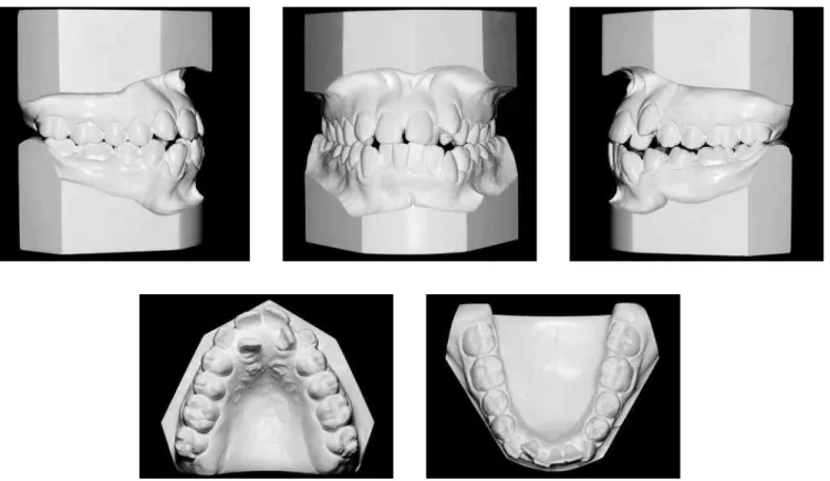
Soares Martins Center for Orthodontics and Facial Orthopedics. A treatment plan was proposed after reviewing data collected in the clinical examination, patient history, intra and extraoral images, comple-mentary exams, cephalometric tracing and orth-odontic models (Fig 1-3). Facial analysis revealed lip incompetence, convex profile, decreased nasolabial
Figure 2 - Initial study models.
lower anterior crowding, with discrepancy of -11.2 mm and -5.5 mm, respectively. Her incisors were in an edge-to-edge relationship, proclined (1-NA=28° and 8 mm, 1-NB=36° and 12 mm), and teeth # 12, 22, 24 and 25 in crossbite, in addition to a tooth size discrepancy9 showing 2.8 mm excess in the lower
anterior region. The degree of complexity found (46 points) made it a highly complex malocclusion.10
The treatment planned for correcting this mal-occlusion involved the extraction of the upper and lower first premolars to eliminate the discrepancy between the teeth and basal bones, and retracting the anterior teeth to balance the facial profile.
The setup procedure comprises the steps de-scribed next (The list of materials used can be found on the website www.dentalpress.com.br/revistas).
Midline registration
Coinciding the upper and lower dental midlines is one of the treatment objectives, be it for aesthetic and/ or functional purposes, be it to accomplish adequate
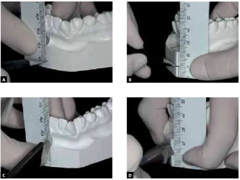
and facing the operator. One must then note the posi-tion of the upper and lower dental midlines relative to the facial midline. In a front view of the patient at rest and with lips slightly parted, one should imagine a line passing through the groove of the upper lip philtrum, and the distance from this line to a midpoint between the upper and lower central incisors should be esti-mated. This patient had a greater than 2 mm midline deviation to the right side while the lower midline co-incided with the facial midline. The transfer of this in-formation to the bases of the upper and lower plaster models, duly supported on a glass plate, is to be per-formed using 0.5 mm mechanical pencil and a ruler. Thereafter, grooves with depth and width of approxi-mately 1 mm should be made in the demarcated sites using a ruler and stylus (Fig 4).
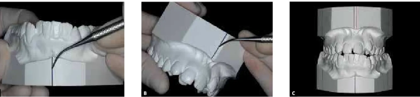
The grooves corresponding to the initial midlines should be filled with blue wax and heated in a dripper, and the registration of the correct midlines targeted by the orthodontic treatment should be performed using heated #7 red wax (Fig. 5). This information
Figure 4 - A, B)Record of the initial upper and lower midlines using a ruler and 0.5 mm mechanical pencil; C, D) grooves with 1 mm width and depth, made with a stylet.
A B
Figure 5 - A, B) Midline grooves filled with heated wax in the lower and upper models; C) filled midlines with initial midlines in blue and the changes planned for the upper midline in red.
A B C
will guide the correct establishment of the midlines when mounting of the teeth.
First molar registration
The mesiodistal axial inclination of upper and lower posterior teeth, preferentially first molars, should also be recorded. In order to verify the axial inclination of these teeth, assuming dental crowns are intact, one can evaluate the relationship be-tween marginal ridges and adjacent teeth, and analyze the relationship of the tooth roots in pan-oramic and/or periapical radiographs. Once these references have been defined, grooves with width and depth of approximately 0.5 mm should be made on the teeth and model bases. On maxillary molar
teeth the grooves must be marked at the center of the mesiobuccal cusp, and on the lower molars the mark should be made on the groove between the mesiobuccal cusp and the median cusp. Both should be extended to the bases of the models using a ruler. However, should the first molars be missing, the second or third molar may be used as reference. These grooves must be filled with blue wax heated in a dripper (Fig 6). If the first molars are missing, the second or third molars can be used as reference.
Recording the position of the upper and lower molars on the model bases is important to check for changes in the movement of these teeth in the an-teroposterior direction, such as loss of anchorage, distalizations or correction of dental inclinations. Figure 6 - A, B) Record of the center of the
up-per molar mesiobuccal cusp and groove between the mesiobuccal cusp and the median cusp on the lower molar; C, D) record of the molar posi-tions on the model bases, and E) tooth and base
grooves filled with blue wax. A B
D E
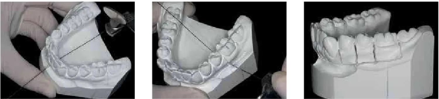
Figure 7 - A) Record of the arch form with 0.021 x 0.026-in stainless steel wire showing its position on the incisal edges and buccal cusps of teeth; B) checking the symmetry chart.
A B
Figure 8 - A) Transfer of the midline of the model to the lingual area of the alveolar ridge; B) record of the anterior posterior position of the lower incisors using condensation cure silicone; C) anterior and posterior incisor extensions of approximately 6 mm.
A B C
Lower dental arch form registration
To avoid relapses, studies recommend that the original form of the lower dental arch not be changed to ensure stability of the occlusion achieved with the orthodontic treatment.11 To record the
origi-nal form, a guiding arch should be prepared using thicker wires, such as stainless steel rectangular 0.021 x 0.026-in or round 0.032-in wires in order to prevent deformation during the phases of the setup procedure. This arch should be fabricated by passing it through the incisal edges of the incisors, canine cusps and buccal cusps of premolars and molars. In mounting the teeth, some modifications may be needed, since the goal is to record the form of the basal bone. Therefore, if the posterior teeth are too buccally inclined relative to the basal bone, the arch should be contracted. If, on the other hand, the teeth exhibit a very pronounced lingual inclination, the arch should have its form further expanded. It is advisable to check the symmetry of this parable in a symmetry chart before starting setup procedure (Fig 7).
Lower incisor registration
The position of the incisors at the end of treat-ment clearly indicates that a successful, satisfactory occlusion and a balanced profile have been achieved.
Figure 10 - A, B, C) Demarcation and removal of the silicone part in the lingual region of incisors to allow the simulation of the retraction of these teeth; D) placement of graph paper.
A B
C D
Figure 9 - Transfer of the midline marked on the model for the silicone and median cutting of this guide.
Then, a piece of graph paper extending vertically and horizontally should be glued to the silicone (Fig 10). This graph paper will serve to quantify the extent to which the simulation of tooth movement is in accordance with the treatment plan, regard-less of whether such movement is an intrusion, extrusion, proclination or retroclination. When the treatment plan provides for proclination or ex-trusion of anterior teeth, before placing the graph paper one should remove part of the silicone in the anterior or superior region to the labial incisal edge, respectively.
Another silicone cure registration must be per-formed in the posterior region to ensure that the
vertical dimension is accurate between the upper and lower models (Fig 11). This record is particu-larly important in cases where there is occlusal in-stability, as in the presence of open bite or when many posterior teeth are missing. Thus, after re-moval of the teeth and while realigning them, one avoids the risk of deviations in the transverse di-rection and loss of vertical dimension.
Tooth identification and cutting
Figure 11 - Registration with silicone in the posterior region to maintain the vertical dimension of the models when mounting the setup model.
Figure 12 - Tooth identification using 0.5 mm mechanical pencil.
Figure 13 - Demarcation of a guideline for cutting the teeth in the model base in both dental arches.
For the removal of the upper and lower teeth, a line must be drawn limiting the region of the alveo-lar ridge, approximately 5 mm from the cervical re-gion of the teeth (Fig 13). Some exceptions should be considered, such as buccal ectopia and gingival recession. It is essential to ensure that the tooth stumps that result from cutting the teeth are high enough to be subsequently attached to the wax.
The models must be drilled in the buccolingual direction, with the aid of a #6 round bur mounted in a handpiece, on the limited horizontal line near the midlines of the teeth. The hole diameter should be about 2 mm, sufficient for inserting a thin spiral saw (Fig 14).
The decision regarding from which lower model quadrant one should start cutting depends on sev-eral factors, including: Midline deviation, crowding, diastemas, lateral open bites and tooth agenesis. In other words, the block of teeth to be initially high-lighted should be opposite to the midline, for exam-ple. In this case, the lower dental midline was cor-rect, but had more than 2 mm deviation to the right. Cutting was therefore started on the opposite side, so that the upper incisor on the left was properly mounted in the middle of dental arch, thus leading to the positioning of other teeth in this segment.
Figure 16 - A, B) Explorer #5 being used to heighten the interdental limits; C) after separating the block of teeth from the model; some finger pressure should be applied to the stumps to separate teeth.
Figure 15 - Horizontal and vertical sections in the lower alveolar ridge of the left quadrant using thin spiral saw mounted on the frame of a bow saw.
A B C
and attached to a bow saw to enable horizontal cut-ting as far as the penultimate tooth, but only in the quadrant chosen. It is recommended that the sec-ond molars not be initially removed in order to help maintain vertical dimension. From the section in the horizontal direction, new sections between the teeth must be made in the vertical direction using a straight saw, taking care not to break the contact points in order to avoid fracturing the dental struc-tures and compromising the mesiodistal dimen-sion of the teeth (Fig 15). After the horizontal and
vertical cutting, an explorer #5 must heighten the interdental limits, providing a guide for the frac-ture line. Only then should a light finger pressure be applied to weaken the embrasures and separate the teeth (Fig 16). The plaster stump of each tooth should be stripped with a steel or tungsten dental bur, slenderizing the stump while carefully preserv-ing the mesiodistal dimension of each tooth without removing the dentogingival limit (Fig 17).
Once the teeth have been prepared, their mesio-distal dimensions should be checked with a caliper,
comparing them with the sizes of the original model of the initial study, which recorded the patient’s malocclusion (Fig 18).
Following, the area corresponding to the base of the alveolar model should be leveled flush with a steel or tungsten carbide cutter to avoid interfer-ences when mounting the teeth. A central groove should be made in the ridge area using the same cutter to preserve the buccal and lingual boundar-ies of the region, as these will be useful when carv-ing the wax. Subsequently, small cavities should be bored with a round bur #6 in order to create re-tention for insertion and fixation of the wax. Soon
afterwards, any debris that may interfere with the wax adhesion should be removed with a brush and/ or compressed air (Fig 19). This entire sequence of procedures should be performed in the ipsilateral quadrant in the upper arch.
Tooth mounting
To mount the teeth, the model base should be pre-pared in the following sequence: Complete filling of the central groove in the alveolar base with a layer of melted red wax #7; placing of a strip of utility wax, also red, with a height of approximately 6 mm (Fig. 20). Using a silicone bite registration, the lower central
A B
C D
Figure 17 - A, B) Stripping the tooth stumps with a steel bur, taking care to maintain the mesial-distal dimension of each tooth, without removing the dentogingival limit; C, D) making retentions in the stumps with a carborundum disk.
A B
C D
Figure 20 - Filling the central groove of the alveolar ridge with red wax #7; a strip of utility wax is attached to the red wax to allow the teeth to be set in place.
Figure 19 - A, B) Leveling the lower alveolar base and making a central groove; C) boring small holes (cavities) with a round bur #6 to create undercuts; D) removal of plaster residues using a compressed air syringe.
incisor is positioned in the utility wax according to the changes proposed in the treatment plan, consid-ering proclination, retraction, intrusion or extru-sion. Next, the remaining teeth are positioned using as reference the archwire form which best represents the original dental arch form (Fig 21). A 3 mm retrac-tion was planned in this case for the lower incisors. After determining the position of the teeth, excess utility wax is removed and the spaces between the teeth filled with hot wax #7 (Fig 22).
When mounting the teeth one should follow the guidelines and the six keys to a normal occlusion introduced by Robert Strang12 and Lawrence
An-drews,13 whereas the arch form and intercanine and
intermolar widths should be preserved.
Once one of the lower quadrants has been fully mounted, the same procedures should be repeated in mounting the upper teeth on the same side, en-suring the best possible intercuspation, while main-taining the vertical and transverse dimensions (Fig 23). After mounting is completed on one side, one must repeat all procedures on the other side of the dental arch (Fig 24).
Figure 21 - A) Positioning the lower left central incisor in accordance with the proposed reduction of 3 mm in the treatment plan; B, C) mounting the remaining quadrant teeth; D) checking for the correct tooth positions using the archwire from the arch form registration.
Figure 23 - A) Mounting of teeth on the upper and lower left side as far as the first molars; B, C) checking to ensure maintenance of the vertical dimen-sion, considering the total height of the bases (initial and setup); if necessary, use of posterior silicone record, illustrated in Figure 11.
Figure 24 - Mounting the left and right quadrants as far as the first molars. The archwire registering the original archform (Fig 7) should be used to check the shape and symmetry of the lower arch construction.
Figure 22 - Setting the tooth stumps with heated red wax #7.
A B
C
A
D
B C
of each quadrant (Fig 25). Once mounting is com-plete, the occlusion should be checked in its contact points, marginal ridge height and axial inclination of the anterior and posterior teeth.
Waxing, carving and finishing
Heated red wax #7 should be placed over and around the stubs, from the alveolar base to the cervi-cal region of all teeth. This type of wax is used because of its greater strength and superior conservation of the setup. The gingival margins are then shaped using a Hollemback carver taking into account the height and shape of the crowns and original ze-niths of each tooth. Maintaining the gingival margin while preparing the teeth can assist in the process of
carving and waxing. The wax should be plasticized using a Hannau type lamp, rendering it thoroughly even and smooth. For finishing, the models should undergo a second procedure, namely, pearling. To this end, the setup should be dipped in a container with soap solution, with the teeth facing down, thus allowing all surfaces to submerge. Within no longer than two hours, the models must be removed from the solution, washed in running water, and rubbed with cotton soaked in the same solution. Finally, it should be allowed to dry for at least 24 hours in a ventilated, dust free environment, on absorbent pa-per, with the teeth facing downwards. Plaster polish-ing should be accomplished by rubbpolish-ing a silk fabric on the teeth and model base (Figs 26, 27).
Figure 25 - Careful removal of the lower second molar, ensuring that the posterior cutting is done exactly on the distal surface of the tooth.
Figure 26 - A) Adjustment and shaping of the gingival margins with a Hollemback carver; B) wax plasticized with the aid of a Hannau lamp to ensure total smoothness; C)immersion in soap solution; D) washing in running water to remove residues; E) plaster polished with silk fabric; F) polishing of gypsum with silk fabric.
A B C
E
Figure 27 - Finished setup model.
SETUP ANALYSIS
Once the setup is ready, much information is gen-erated and if a judicious method is not used to analyze it one may not derive its full benefits. The use of an evaluation form based on the model, first suggested by Cury-Saramago and Vilella14 is recommended. The
proposed method includes ten items: Extractions, changes in the basal bones, lower incisor position, leveling, midlines, dental arch form, molar and ca-nine relationship, anchorage, interproximal stripping and cosmetic finishing (Fig 28). The manner in which data are acquired and recorded, as well as the type of information that can be obtained will be presented below, along with remarks on the analysis of the clini-cal case presented in this article (Fig 27).
Extractions
Under this topic one should record the extrac-tions which were necessary for treating the maloc-clusion. Additionally, the mesiodistal dimensions of the extracted teeth should be recorded as these
dimensions are an indication of the space gained for alignment, leveling, repositioning of the anterior teeth and correction of the midlines. In the example described above, teeth numbers 14, 24, 34 and 44 were extracted, resulting in a space gain of 16.8 mm in the upper and 17 mm in the lower arch.
Basal bones
Under this item one should record the amount of growth planned for the treatment period, and the extent of maxillary/mandibular advancement or setback determined in planning orthognathic sur-gery, which can be measured by the extent of wax placed on the posterior edge of the models. Since this was not a growing patient and surgery was not planned, nothing was recorded on the card.
Lower incisors
Patient: Age: Date:
1. EXTRACTIONS
1.1 Yes: (x) No: ( )
1.2 Space gained: Upper Lower:
2. BASAL BONES
2.1 Growth: ( ) Surgery: ( ) None: (X)
3. LOWER INCISORS
3.1 Retraction: (X) Proclination: ( ) Maintenance: ( )
3.2 Intrusion: ( ) Extrusion: ()
4. LEVELING
4.1 Overbite - Initial: Setup:
4.2 Intrusion: ( ) Extrusion: (X)
5. MIDLINES
5.1 Upper - Initial: Setup:
5.2 Lower - Initial: Setup:
5.3 Space - Extraction: (X) Distalization: ( ) Interproximal stripping: ( )
6. DENTAL ARCH FORM
6.1 Lower - Expansion: (X) Contraction: (X) Maintenance: ( )
Widths - Intermolar - Initial: Setup: Intercanine: Initial: Setup:
6.2 Upper - Expansion: (X) Contraction: ( ) Maintenance: ( )
Widths - Intermolar - Initial: Setup: Intercanine: Initial: Setup:
7. MOLAR AND CANINE ANTEROPOSTERIOR RELATIONSHIP
7.1 Intermolar - Initial: Right: Left:
Setup: Right: Left:
7.2 Intercanine - Initial: Right: Left:
Setup: Right: Left:
7.3 Intercuspation - Satisfactory: (X) - Limitations: ( )
8. ANCHORAGE
8.1 Anchorage loss: (X) Upper Right: Left: Lower Right: Left: 8.2 Distal movement: ( ) Upper Right: Left: Lower Right: Left:
9. INTERPROXIMAL STRIPPING
9.1 3 to 3 - Upper: ( ) Lower: (X)
9.2 4 to 6 - Upper: ( ) Lower: ( )
9.3 Tooth size discrepancy - 6 anterior teeth: (X) 12: ( )
10. COSMETIC FINISHING 10.1 Stripping: (X) 10.2 Augmentation: ( )
Figure 28 - Form used for setup analysis.
Teeth 14, 24, 34 and 44
ACGB 14 years 04/29/2002
16.8 mm (8.4 + 8.4)
3 mm
17 mm (8.5 + 8.5)
0 mm
upper incisors 2 mm
2.8 mm lower teeth
3.5 mm 3.0 mm 4.0 mm 3.5 mm
2.8 mm in teeth 32, 42, 33 and 43
lingual marginal ridges of teeth 11 and 21 45 mm
51 mm
44 mm
52 mm deviated 2 mm to the right
canines
Class I occlusion
Class I occlusion Class I occlusion
Class I occlusion
Class I occlusion
Class I occlusion Class I occlusion
Class I occlusion molars
pre-molars
coincident
coincident coincident
30.5 mm 37 mm
26.5 mm 28 mm
Leveling
To assess changes in dental leveling one should note the amount of overbite and curve of Spee pres-ent in the initial malocclusion, and the correction made in the setup. It is important to stress that this leveling occurred by intrusion or extrusion of ante-rior or posteante-rior teeth accomplished according to the diagnosis and treatment plan. In the case presented in this study, the edge-to-edge relationship in the an-terior region identified at the beginning of treatment was corrected by extruding the upper incisors.
Midlines
One should record the changes made in the up-per and lower midlines (Fig 27), and how space was obtained for this procedure, such as premolar ex-tractions, distalization of posterior teeth or strip-ping. In the setup described in this study, the upper midline was corrected by deviating it 2 mm to the left; space was gained from premolar extractions.
Dental arches
In order to evaluate the lower dental arch form once the setup is complete, one should use an arch-wire form compatible with the original dental arch form (Fig 7). In this case, it can be observed that the form was retained to the extent possible (Fig 24C). One should also compare the distances between the upper and lower canines and molars on the setup with the measurements obtained from the mod-els that contain the malocclusion, and record the changes. In the clinical case there was practically no changes in the intermolar distance in both arches, the intercanine width, on the other hand, increased due to the fact that these teeth were distalized to achieve leveling, alignment and incisor retraction.
Molars and canines
In this section, one should record, in addition to the initial relationship of these teeth, the position they occupy after simulating the treatment, and
marks in the aforesaid teeth at their final positions (Fig 27). Intercuspation should be assessed, and any difficulty in mounting the setup, noted. This step is important as it enhances treatment predictability given the possibility that the same problems may also occur during orthodontic therapy. In this case, the relationship of the molars and canines in the an-teroposterior direction was maintained. Intercus-pation was improved thanks to the space obtained from the extractions.
Anchorage
Any anterior posterior movement observed in the molars must be recorded. For this purpose, a ruler is placed on the base of the model, and the reg-istration line is extended from the starting position of the molars. Thus, one can measure with another ruler the amount and direction (mesial or distal) of tooth movement. Another form of assessment is to measure the distance between the distal end of the last tooth and the retromolar region in the upper and lower arches. However, this method is effec-tive only if this region has been carefully cut at the distal end of the last tooth in the setup model. This information will be useful for planning the anchor-age to be used in the orthodontic treatment of the malocclusion. In the case described in this article, 3.5 mm anchorage was lost in the upper right quad-rant, 3 mm in the upper left quadquad-rant, 4 mm in the lower right quadrant and 3.5 mm in the lower left quadrant. Planning the anchorage for treating the aforementioned malocclusion required the use of a Nance button and lingual bar.
Interproximal stripping
Figure 29 - Finished treatment showing the treatment objectives were achieved according to plan.
posterior segment, or both. It is important to note that this stripping should only be carried out when Bolton discrepancy9 is present, or else a Bolton
dis-crepancy will be created in the opposing arch. Prior to stripping, one should also ascertain that the sizes of all teeth are symmetrical, since if tooth symmetry is not present, the teeth with larger mesiodistal di-mensions should be stripped first, thereby establish-ing symmetry with the homologous teeth. In the case
Figure 30 - Final study models.
that may interfere with a proper posterior intercus-pation. The need for gradual reshaping in the case of microteeth, asymmetries of homologous teeth, Bolton discrepancy, or large teeth showing signs of substantial incisal wear should also be noted. Af-ter achieving the best possible inAf-tercuspation it is important to record the factors that hindered the achievement of an even better intercuspation. Some such factors are the presence of eccentric or worn cusps, restorations with improper shape or size, as well as teeth with increased or decreased buccolin-gual dimensions. In this case, some stripping of the palatal ridges of teeth 11 and 21 was performed.
Figure 32 - A) Total and B) partial superimpositions of initial (black) and final (red) cephalomet-ric tracings.
A B
Figure 31 - Profile and panoramic radiographs, and final cephalometric tracing.
this treatment received 9 points, which is consid-ered a good finishing score.
With the development of and reduction in the cost of three-dimensional scanning technology, along with the ability to perform computerized analyses, virtual models of the dental arches have become increasingly common in clinical orthodon-tics. The computer programs designed to meet this market demand are becoming increasingly effective and thorough. Today, it is possible to quickly and easily analyze asymmetries, space discrepancies,
Figure 33 - Digital setup performed with OrthoAnalyzer software.
1. Hou HM, Wong RWK, Hägg U. The uses of orthodontic study models in diagnosis and treatment planning. Hong Kong Dent J. 2006;3(2):107-15.
2. Bolognese AM, Mucha JN, Mangim VCN, Moreira TC, Goraieb SM, Menezes LM, et al. Setup: uma técnica de confecção. Rev Soc Bras Ortodon. 1995;2(8):245-9. 3. Tavares CAE, Zanini LK. A confecção do “Set up” de diagnóstico ortodôntico. Rev
Dental Press Ortod Ortop Facial. 1999;4(5):20-3.
4. Ruellas ACO. Montagem de diagnóstico ortodôntico simplificado (set up). J Bras Ortodon Ortop Facial. 2000;5(30):57-60.
5. Vianna MS, Saga AY, Casagrande FA, Camargo ES. Setup: um auxílio no diagnóstico ortodôntico. J Bras Ortodon Ortop Facial. 2002;7(11):398-405.
6. Kesling HD. The diagnostic setup with consideration of the third dimension. Am J Orthod. 1956;42(10):740-8.
7. Andrade BNG, Almeida RC, Carvalho FAR, Quintão CCA, Almeida MAO. Avaliação da confiabilidade do setup no diagnóstico e planejamento ortodôntico. Ortodontia. 2010;43(4):389-95.
8. Habib F, Fleischmann LA, Gama SKC, Araújo TM. Obtenção de modelos ortodônticos. Rev Dental Press Ortod Ortop Facial. 2007;12(3):146-56.
REFERENCES
when simulating the tooth movements according to the manual setup construction method described in this article. Figure 33 shows the digital setup of one and the same patient.
Finally, a manual or digital reading of the setup is recommended, recording all information obtained
9. Bolton WA. The clinical application of tooth size analysis. Am J Orthod. 1962;48(7):504-29.
10. Cangialosi TJ, Riolo ML, Owens SE Jr, Dykhouse VJ, Moffitt AH, Grubb JE, et al. The ABO discrepancy index: a measure of case complexity. Am J Orthod Dentofacial Orthop. 2004;125(3):270-8.
11. Triviño T, Siqueira DF, Scanavini MA. A forma do arco dentário inferior na visão da literatura. Rev Dental Press Ortod Ortop Facial. 2007;12(6):61-72.
12. Strang RH, Thompson WM. A textbook of Orthodontia. 4th. ed. Philadelphia: Lea & Febiger; 1958.
13. Andrews LF. The six keys to normal occlusion. Am J Orthod Dentofacial Orthop. 1972;62(3):296-309.
14. Cury-Saramago AA, Vilella OV. Analisando o setup. Rev Soc Bras Ortodon. 2005;5(2):107-18.
15. Casko JS, Vaden JL, Kokich VG, Damone J, James RD, Cangialosi TJ, et al. Objective grading system for dental casts and panoramic radiographs. Am J Orthod Dentofacial Orthop. 1998;114(5):589-99.