Determination of Gaseous Analytes in Flow Systems.
A Review
Celio Pasquini*, and Maria do Carmo Hespanhol da Silva
Instituto de Química, Universidade Estadual de Campinas,
C.P. 6154, 13083-970 Campinas - SP, Brazil
Uma revisão crítica dos trabalhos visando a aplicação de sistemas de análises químicas em fluxo à determinação de analitos gasosos em amostras gasosas é apresentada. Os sistemas em fluxo constituem em uma alternativa apropriada para manipulação e processamento de amostras gasosas sendo, no entanto, encontrados na literatura um número relativamente pequeno de trabalhos relacionados a este assunto. Por outro lado, o advento de sistemas automatizados utilizando microcomputadores e de novos dispositivos, tais como válvulas solenóides miniaturizadas, as quais facilitam a manipulação das amostras gasosas, o fácil acesso a padrões gasosos, e o aumento da demanda por determinações de analitos gasosos, têm contribuído para o recente progresso associado ao uso de sistemas em fluxo. Pode-se concluir que os sistemas em fluxo constituem uma opção rápida, versátil, capaz de ser aplicada a uma ampla faixa de concentração, de fácil operação com consumo de amostra relativamente pequeno, constituindo-se em uma alternativa de baixo custo para determinação de analitos gasosos.
Efforts to develop flow systems for the determination of gaseous analytes in gaseous samples are critically reviewed. Although flow systems present a suitable alternative to management and processing of gaseous samples, relatively few papers dealing with this subject are found in the literature. The increased demand for determination of gaseous analytes, the advent of automated systems based on microcomputers and new devices, such as miniature solenoid valves, which facilitate manipulation of gaseous samples, and the easy access to gaseous standards has, along, driven some recent progress towards the use of flow systems. Flow systems constitute a versatile option capable to be applied to a wide concentration range, rapid, easy to operate with relatively low sample volume, becoming a low cost approach for determination of gaseous analytes.
Keywords:gaseous analytes, flow analysis, gas analysis
Introduction
Interest in the determination of analytes present in the atmosphere for environmental monitoring and control could alone justify the efforts aiming to develop analytical methodologies dealing with the determination of gaseous analytes in gaseous samples. However, the interest in such determinations is broadened in fields such as respirometry, production of synthetic gaseous mixtures for use in hospi-tals and industries, packaging atmospheres for food preser-vation, and occupational exposure, to mention only but a few.
Determination of gaseous analytes requires analytical methods able of dealing with wide concentration ranges that go from a few volumetric parts per billion to parts per cent. To suit the analyte properties, and their concentration ranges, the analytical method should be capable to employ
various detection techniques, which can provide the neces-sary detectability and selectivity.
The most employed techniques for gas analysis include chromatography and dedicated gas analysers based on di-rect detection of the analyte by, for example, IR absorption, fluorescence or specific solid state sensors. Chromatogra-phy posses high versatility and can deal with analysis of gaseous mixtures and identification of individual compo-nents in a gaseous mixture. Detectability is good but opera-tion of the instrument is complex whereas its cost is high and the determination of a single analyte may require about 10 min. Dedicated instruments often lack versatility and thus cannot be properly considered low cost, in view of their limited versatility. The aspects related to low cost and versatility in gas analysis are being explored by the meth-ods based on flowing media as presented in this review. Review
Gaseous samples are fluids that can be transported inside the flow analyser manifolds. Their interaction with liquid fluid media, employed in flow systems, could be easily predicted. However, despite the fact that the first flow analysis principle1, was based on the coexistence of liquid and gaseous phases inside the analyser manifold, continuous flow analysis has never been used for determi-nation of gaseous samples. On the other hand, in modern unsegmented or monosegmented flow systems this interac-tion has been promoted in a number of different ways. The way how interaction is achieved does not matter, the intent is always the same, namely, to transfer the gaseous analyte to a liquid phase to be further processed and/or detected.
In this paper any system where the contact area between the liquid phase and gaseous sample is renewable, it is considered as a flow system developed for the determina-tion of gaseous analytes. The renewal of the contact area is achieved by flushing, at some stage of the process, the liquid phase. The possibility of reagent renewal is, perhaps, the main advantage of flow systems applied to gas analysis. In view of the above definition, this paper does not include those works in which a flow system is employed to determine an analyte that can be volatilised under certain conditions but that is found initially dissolved in a liquid or solid sample. For the same reason, the systems where the couple between the gaseous sample and liquid phase is not made directly inside the analyser and in which the gas sample is previously scrubbed into a liquid solution (i.e., a batch operation accomplished outside the flow manifold) which is further introduced into a flow system, is also not considered. In these cases, the gaseous sample is, in fact, effectively converted to a liquid sample.
General Approach to Flow Analysis Applied
to Gaseous Samples
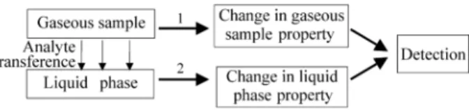
Figure 1 shows the usual steps associated with flow systems designed for determination of gaseous analytes in gaseous samples. To date, the only properties directly associated to the gaseous sample, employed in flow sys-tems (path 1, Fig. 1) make use of the volume contraction resulting from analyte absorption by the liquid phase2 or of a gas phase reaction to produce a temperature change in the acceptor stream3. Other flow systems exploit a change in a liquid phase property (path 2) as, for example, the forma-tion of a light absorbing compound by reacforma-tion between a reagent and the absorbed analyte, a change in conductivity or inhibition of chemiluminescence intensity. Detectability of such an approach is dependent mainly on the efficiency of analyte transference to the liquid phase, and on the characteristic of the change in the liquid property and its dependence on the analyte quantity. This last factor is determined, for example, by the molar absorptivity of the compound formed after reaction between the reagent and
analyte. Selectivity is usually attained by the reaction oc-curring between the analyte and a reagent present in the liquid phase, although the use of membranes or permeation tubes can be also employed, mainly to prevent interferences of particulate matter.
Systems Employed only for Gas Sampling
and Transportation
After the introduction of the Flow Injection (FI) concept to flow analysis, a paper was published in which the adap-tation of FI to gaseous sample analysis was implemented by using the system only for gas transportation and sam-pling4. An inert gas was employed to transport the injected gaseous sample towards a solid interface where an absorp-tion reacabsorp-tion occurred. The advantages of such an approach were the improvement in precision of the sampling volume and the easy of sample manipulation while increasing the sample throughput. The general principle could be used for adaptation of any specific detector to a FI system with the advantages described above and some works reporting this have been published5-8.
Systems Employing Intermittent Flow of the
Liquid Absorbing Phase
Holding a small volume of the liquid absorbing phase and promoting its contact with a large volume of the gaseous sample to concentrate the analyte is a practice that can be adopted to increase the detectability. The acceptor solution can be retained as a film on the tube wall, in small volumes isolated from the gaseous sample by a membrane or a porous polymer tube or as a hanging drop at the end of a capillary tube.
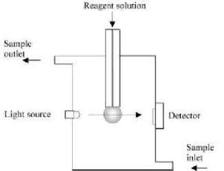
Within this approach, a number of papers have been published making use of a hanging drop of an acceptor solution. This approach was introduced by Dasgupta and co-workers9,10 and results in an intermittent flow system such as that depicted in Fig. 2. The property of the liquid phase followed is the change in light absorbance caused by the reaction of the analyte with a reagent present in the liquid drop. On finishing a determination, the drop is re-moved, a fresh solution of the absorbing solution is pumped into position, and the system is ready for another determi-nation. The system has the advantage of the reproducibility of the drop volume and suitable detectability was achieved for the determination of NO2. Another advantage is the very
low consumption of reagents. On the other hand, the effi-ciency of analyte transportation to the drop depends on the gas sample flow rate and this has not yet been evaluated for the proposed systems9,10. The system requires an external control of the sample flow rate (which needs to be constant) and/or use of a volume sampling device. Detection itself is difficult in view of the need for a light beam alignment on a small curved cross section of the drop. The optical path, a parameter that can be used to improve the detectability, is restricted by the drop size and, in this case, is small compared with other systems. Sample throughput, as in most of the systems employing in-line concentration, is a function of the required detectability.
Other systems, employing intermittent flow, have been proposed in which the acceptor reagent solution is held in a section of a flow cell and separated by a PTFE membrane, as shown in Fig. 311-15, inside a inner porous tube of a two concentric tube denuder12,15 or as film on the inner wall of a single tube denuder16.
In the membrane approach and in the two-tube denuder approach the gaseous sample is impelled under constant flow through the upper part of the cell or through the inner porous tube. The gaseous analyte permeates the membrane or the tube wall and is collected by a suitable reagent solution. Recently the membrane permeation cell was im-proved by having detection in a cell employing an optical path of 2.4 cm. This was applied in a system for the determination of NO2 13. The detectability achieved is of few ppbv(nL L-1) of NO2 in air. However, for this last system, transference of the analyte is only about 2% of the original quantity present in the sample, as the permeation step is a slow process. A compromise between sample flow rate and analyte transference does exist. On average, about 10 samples can be processed in an hour, and the detectabi-lity is satisfactory for determination of NO2 in atmospheric air. As a positive feature, the use of membrane permeation
prevents interference caused by particles present in the gaseous sample.
Another simple and ingenious approach to gas collec-tion for further introduccollec-tion to a flow system is based on a capillary loop that is first dipped in the collecting solution and then exposed to the gas sample17. The small volume of solution retained by the capillary loop acts as a resevoir. The system has been employed with a capillary electropho-resis separation system but its use along with flow systems could be easily achieved.
Systems Based on Flowing Liquid/Gas
Acceptor
The systems employing static acceptor solutions for in-line analyte concentration can also be used with the acceptor liquid flowing continuously. Usually a lower de-tectability is obtained but the overall operation of the analyser is simplified. Most of the flow systems described so far in the literature make use of a continuously flowing acceptor solution. However, there are different ways to produce the flowing acceptor stream and to promote the contact between the gaseous sample and the absorber. These kinds of systems can be classified as described below.
Flow Injection Systems
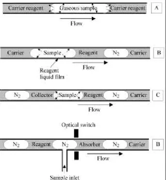
The direct injection of the gaseous sample in a suitable carrier/reagent solution in FI systems has been proposed as an alternative to perform a truly non-stop flow determina-tion of the gaseous analyte18. Figure 4A shows how analyte transference from gas to liquid/reagent carrier is accom-plished. Although the authors that have employed this approach do not discuss it, transference of the gaseous analyte to the reagent solution would be processed through the liquid-gas interface and also by having some of the analyte adsorbed on the hydrophobic material of the tubing wall (usually PTFE or polyethylene) and further trans-ported towards the liquid phase. The species formed in the liquid phase is subjected to dispersion in the carrier/absorb-ing fluid.
Figure 2. Schematic presentation of the hanging drop / dropping flow system for spectrophotometric gaseous analyte determination.
Early works considered that the passage of the gaseous portion of the flow pattern, generated by the sample intro-duction, would affect the analytical signal. This was true in the earlier FI systems when a chart recorder was employed. The detectability was, therefore, sometimes sacrificed in order to remove the residual gaseous sample prior to detec-tion18,19.
To avoid perturbation of the detection system caused by passage of the gaseous portion without its prior separa-tion, a flow system was developed in which the flow direction is sequentially reversed. This operation prevents the injected gaseous sample from reaching the detector while the transfer of the analyte is maximised20. The num-ber of cycles of reversion determines the detectability of the determination as more analyte is incorporated in the absorbing solution in each flow inversion operation. How-ever, data on the efficiency of the analyte transfer achieved in such systems were not reported.
The determination of CO2 in concentration ranges of interest for atmospheric air has been proposed by injecting the gaseous sample in a liquid flow system and permeating the CO2 through a PTFE membrane to a deionised water acceptor stream. The change in conductivity of this stream caused by the collection (which embodies dissolution fol-lowed by ionization) of the carbon dioxide was employed as the analytical signal21.
Another FI system for determination of high contents of NH3 used membrane permeation and a gaseous acceptor stream containing CO2 and H2O vapour to react with the permeated NH3, producing a change in the temperature of the acceptor gaseous phase which is sensed by a thermis-tor3.
Continuous Film Flow and Dropping
Systems
A flowing film or growing/falling drop acceptor solu-tion was employed for the determinasolu-tion of hydroperoxides and gaseous chlorine9,22. The system for determination of hydroperoxides differs from that for chlorine because the acceptor solution first flows as a thin film formed outside a capillary. The film absorbs the analyte which is trans-ported towards an electrochemical voltammetric detector which operates in the drop formed by the slowly flowing (50 µL min-1) acceptor solution. Detection for the chlorine determination is spectrophotometric and is made directly in the growing drop which is renewed continuously and acts as the absorber.
Monosegmented and Bisegmented Flow
Systems
Recently the monosegmented flow approach23 ex-ploited for gaseous sample determination. The system has the intrinsic characteristic of simultaneous introduction of
gas and liquid phases in to the manifold. The monoseg-mented system generates the flow pattern, in Figure 4B, after a single movement of the sample introduction device. Immediately after introduction, the central liquid monoseg-ment does not contain the reagent which is added further in the manifold24. As the material employed for the manifold construction is glass (a hydrophilic material) a thin film of the reagent solution is produced on the wall of the tube manifold. The sample is carried over this film and the analyte transference yield is improved over systems em-ploying membranes and/or FI systems where dispersion of the product in the liquid phase causes a reduction of the sensitivity.
This monosegmented system has been employed for determination of CO2 and O2 in concentrations higher than 2% (v/v) by following the volume contraction of the in-jected sample2. This parameter was evaluated by accessing the time elapsed for the gaseous sample segment to cross two optical switches fixed in the glass tube. The first optical switch finds the volume before analyte absorption and the second (at the end of the reactor tube) finds the volume after absorption. Two procedures have been developed. One is based on the assumption of total analyte absorption and the other (more accurate) based on calibration with standards. Studies reveal that O2 absorption by a layer of pyrogallate
in a strong alkaline medium is near 100% for gaseous samples containing the O2 in the range of 2-40%(v/v) and CO2 in the range 5-40%. The monosegmented system present low dependence on temperature fluctuations as the two volume measurements of the gas sample are made within less than one minute of each other.
The monosegmented system was also employed for CO2 determination in concentration range it is found in atmospheric air (100-800 ppmv)25. In this case, no reagent is used and the change in conductivity of the deionised water present in the liquid segment is monitored.
A bisegmented system was conceived with the purpose to employ path 2 of the general approach on the use of flow systems in gas analysis. Figure 4C shows the flow pattern employed for a continuous operation of the flow system. As in the monosegmented system, the complex flow pattern is generated in a simple way by the sampling device. The first liquid segment of the pattern contains the reagent and creates an absorbing layer on the glass tube wall. The gaseous sample, introduced in a repeatable volume, runs over the reagent film and forms a product that is retained in the layer. The second liquid segment comes later, remov-ing the product from the layer and transportremov-ing it to the detector.
The system was used for spectrophotometric determi-nation of O2 (using alkaline pyrogallate as the color-form-ing reagent) in samples containcolor-form-ing the analyte in concentrations in the range 0.2 - 1%(v/v)26.
The bisegmented system can be arranged to work in the intermittent flow mode allowing analyte in-line concentra-tion as shown in Fig. 4D26. The approach was also applied to NO2 determination. In that case the absorbing solution contains triethanolamine and the reagent liquid is that proposed by Griess and commonly employed for the deter-mination of NO2- in liquid solutions. The main advantage of this system is to permit two different media, one used for absorption and other for reaction. This characteristics can improve the versatility of the flow system. Because the system promotes a direct and well favoured contact (due the large contact surface) between the gaseous analyte and the absorbing or reacting solution, the transference yield is favoured and was determined to reach about 80% of the analyte quantity present in the sample volume26.
Steady State Flow Systems
Several works can be found in which the gaseous sam-ple and the liquid absorbing solution are placed in contact, with both flowing continuously. A steady analytical signal is obtained reflecting the content of the gaseous analyte and allowing for real time monitoring27,28. In one of the sys-tems27, the contact between sample and reagent is attained by segmentation of the absorbing liquid with the gaseous sample. The system has been employed for determination of H2S in atmospheric air. A separation of the gaseous
phase is employed before spectrophotometric monitoring of the liquid phase.
In another work28, the gaseous sample is blown onto the surface of a specially constructed cell where the enhace-ment of luminol-cobalt(II) phthalocyanine chemilumine-cence, caused by the CO2 present in the gaseous sample, is observed. In this last system the sample can be also injected in a discrete volume and the system approximates a FI system.
Finally another continuous flow system was described in which the sample and acceptor gaseous streams are separated by a silicone membrane29 The system was ap-plied to the determination of SO2 using a coulometric detector.
Survey on the Gaseous Analytes Determined
by Flow Systems
Table 1 summarises the gaseous analytes determined by flow based methods and their principal characteristics. Several authors do not report an interference study. Some-times it is assumed that the same interferences, shown by the conventional batch procedure and made with the use of the same reagent employed in the flow system, occur in the flow system. Although this is true for most of the cases, a detailed investigation of the degree the interference occur-ring in the flow system is always advised because, under dynamic and kinetically controlled conditions, the relative interference can change for each concomitant.
Conclusion
Use of the flow approach, in its various forms, has revealed that it constitutes a valuable analytical tool for gaseous analyte determination in gaseous samples. The methods developed under this approach are rapid, versatile, able to using low sample volumes and result in a low cost both per determination and for the analyser. Under these aspects the flow systems compete favourably with chroma-tography or dedicated instruments employing solid state sensors.
The flow systems developed have demonstrated that they can be used for determination of gaseous analytes present in a wide concentration range. Direct determination in true, continuous flow systems is possible while, if the concentration range of the analyte is very low, the system can be operated in the intermittent flow mode to precon-centrate the analyte in a small volume of the absorbing/re-agent solution before detection, improving the detectability of the determination. Some of the developed systems have not been applied to real samples; the necessary and detailed investigation concerning this aspect can show the true capabilities of those systems.
addi-P as q u in i & d a S ilv a J . B ra z. C h em . S o c .
Table 1. Gaseous analytes determined by flow systems.
Analyte Concentration (v/v)
Matrix Samples h-1
Detection / Flow technique Reference
NO2 500ppm -- 10%
30 --100 ppb 24 --122 ppb 0.05 - 97 ppb 25 -- 200 ppb 1 -- 500 ppm
Synthetic air Synthetic air Synthetic air N2 Synthetic air Synthetic air 60 12 10 20 5 24
Spectrophotometry / Reversal FI+ Spectrophotometry / Drop-Liquid film flow
Spectrophotometry / Intermittent flow / Membrane denuder / Permeation cell Potentiometric / Intermittent flow / Membrane permeation
Spectrophotometry / Bisegmented flow Galvanic detection / FI for sample transport
20 10 13 14 26 8
O2 1 -- 80%
0.1 -- 2%
0.5 -- 19%
N2/O2/CO2 Food packaging
atmosphere Atmosphere over
post-climateric fruits
30 30
200
Volume contraction / Monosegmented flow Spectrophotometry / Bisegmented flow
O2 electrochemical analyser / FI for sample transportation
2 26 5
NH3 1.3 - 197 ppb Synthetic air 12 -- 60 Potentiometric / Tubular membrane continuous flow or FI 12
CO2 9.4%
1 -- 40% 50 -- 800 ppm
1 -- 100% 100 -- 800 ppm
0.3 -- 20% 50 -- 600 ppm
Synthetic air Synthetic mixtures Human breath Synthetic mixtures Synthetic air Synthetic mixtures Atmospheric air 20-110 30 900 60 6-60 60
Thermometry / FI
Volume contraction / Monosegmented flow Chemiluminescence / Continuous flow/ FI
Conductimetry / Monosegmented flow
Conductimetry / Spectrophotometry / Intermittent flow/ Silicone membrane Conductimetry / FI membrane permeation
3 2 28 25 15 21
Cl2 0 -- 1100 ppb
4 -- 70 ppm
Filtered house air Synthetic air
30 100-120
Spectrophotometric / Dropping collecting flow Solid phase spectrophotometry / FI
9 4
Br2 4 -- 70 ppm Synthetic air 100-120 Solid phase spectrophotometry / FI 4
H2S 0.092 - 11.5 ppb 0 -- 0.4%
Atmospheric air Synthetic mixtures
* 30
Fluorimetry / Continuous flow
Spectrophotometric / intermittent flow/ Silicone membrane / FI
27 15 HCN 50 -- 150 ppm Synthetic air 12 Spectrophotometry / Intermittent flow/ Silicone membrane / FI 15
Hydroperoxides 12 -- 200 ppb Atmospheric air 40 Voltammetry / Film / Dropping flow 22
SO2 1.7 -- 175 ppb
30 -- 627 ppb 0.5 -- 15.0 ppm
10-1000 ppm Synthetic air Atmospheric air Synthetic air/ Indoor air Synthetic samples 30 9 20-50 *
Spectrophotometry/ Continuous/Intermittent flow/ FI Conductimetry/ FI
Spectrophotometric / FI
Coulometric / Silicone membrane/ Continuous Flow
12 16 18
29 + Flow Injection.
tional research efforts should be addressed to make use of changes in properties of the gas samples directly instead of properties related to the liquid phase, which have been successfully employed by most of the flow methods devel-oped so far. In this aspect, reactions in the gaseous phase and gaseous properties such as thermal conductivity and gas phase fluorescence and absorption, along with hyphen-ated systems, constructed by coupling the flow manifold to mass detection, for example, should be evaluated in the future.
Acknowledgements
The authors are grateful to Dr. C.H. Collins for manu-script language revision. M.C.H.S. is grateful to FAPESP for a fellowship (proc. no. 95/06756-0).
References
1. Skeggs, L.T. Am. J. Clin. Pathol.1957, 28, 311. 2. da Silva, M.C.H.; Pasquini, C. Anal. Chim. Acta1997,
349, 377.
3. Liu, S.J.; Tubino, M. Anal. Chim. Acta1998,366, 5. 4. Ramasamy, S.M.; Jabbar, M.S.A.; Mottola, H.A.
Anal. Chem.1980, 52, 2062.
5. Saltveit Jr, M.E; Strike, T. HortScience1989, 24 145. 6. Alexander, P.W.; Di Benedetto, L.T.; Dimitrakopou-los, T.; Hibbert, D.B.; Ngila, J.C.; Sequeira, M.; Shiels, D. Talanta1996, 43, 915.
7. Alava-Moreno, F.; Valencia-González, M.J.; Sanz-Medel, A.; Díaz-García, M.E. Analyst1997, 122, 807. 8. Liu, S.J.; Shen, H.X.; Feng, J.X.; Tubino, M. J. Autom.
Chem.1998, 20, 17.
9. Liu, H.; Dasgupta, P.K. Anal. Chem. 1995, 67, 2042. 10. Cardoso, A.A.; Dasgupta, P.K. Anal. Chem. 1995,67,
2562.
11. Pranitis, D.M.; Meyerhoff, M.E. Anal. Chem.1987,
59, 2345.
12. Frenzel, W. Anal. Chim. Acta, 1994, 291, 305. 13. Schepers, D.; Schulze, G.; Frenzel, W. Anal Chim.
Acta 1995,308 109.
14. Frenzel, W. Fresenius J. Anal. Chem.1990, 336, 21. 15. Kubáñ, V. Scripta Fac. Sci. Nat. Univ. Masaryk. Brun.
1994,24, 43.
16. Gács, I.; Ferraroli, R. Anal. Chim. Acta 1992, 269, 177.
17. Dasgupta, P.K.; Kar, S. Anal. Chem. 1995, 67, 3853. 18. Ramasamy, S.M.; Mottola, H. A. Anal. Chem.1982,
54 283.
19. Ríos, A.; Luque de Castro, M.D.; Valcárcel, M.; Mot-tola, H.A. Anal. Chem. 1987, 59 666.
20. Cañete, F.; Ríos, F.C.A.; Luque de Castro, M.D.; Valcárcel, M. Anal. Chim. Acta 1989, 224 127. 21. Guimarães, J.R. PhD Thesis; Universidade Estadual
de Campinas; Campinas; São Paulo; Brazil, 1995. 22. Huang, H.; Dasgupta, P.K. Talanta1997, 44, 605. 23. Pasquini, C.; de Oliveira, W.A. Anal. Chem. 1985, 57,
2575.
24. Raimundo Jr., I.M.; Pasquini, C. Analyst1997, 122, 1039.
25. da Silva, M.C.H.; Rohwedder, J.J.R.; Pasquini, C.
Anal. Chim. Acta 1998, 366, 223.
26. da Silva, M.C.H.; Pasquini, C. Anal. Chim. Acta, accepted for publication, 1999.
27. Jaeschke, W.; Schunn, H.; Haunold, W. Fresenius J. Anal. Chem. 1995, 351, 27.
28. Lan, Z.H.; Motolla, H.A. Anal. Chim. Acta, 1996, 329, 305.
29. Liu, S.J.; Shen, H.X.; Feng, J.X.; Tubino, M. Fre-senius J. Anal. Chem.1997, 357, 1045.
Received: February 26, 1999