Numerical and Experimental Study of a Real Scale
Wafle Slab
Análise Teórico-Experimental de uma Laje Nervurada
em Escala Natural
P. F. SCHWETZ a
F. P. S. L. GASTAL b [email protected]
L. C. P. SILVA F° C
a Departamento de Engenharia Civil, Universidade Federal do Rio Grande do Sul, [email protected], Av. Osvaldo Aranha, 99 – Térreo,
CEP 90035-190, Porto Alegre, Brasil;
b Departamento de Engenharia Civil, Universidade Federal do Rio Grande do Sul, [email protected], Av. Osvaldo Aranha, 99 – Térreo, CEP 90035-190,
Porto Alegre, Brasil.
c Departamento de Engenharia Civil, Universidade Federal do Rio Grande do Sul, [email protected], Av. Osvaldo Aranha, 99 – Térreo,
CEP 90035-190, Porto Alegre, Brasil.
Abstract
Resumo
Nowadays, wafle slabs are a demand for structural designers, as a consequence of architectural design evolution and new building management concepts, in spite of its laborious numerical modeling. Therefore, it becomes necessary to know more about the structural behavior and improve the theoretical models used for simulating these slabs. The objective of this work was to analyze the adequacy of a design method widely used in the modeling of wafle slabs, verifying if it represents the slab behavior satisfactorily. A real scale wafle slab submitted to a load in a localized area was instrumented with strain gages and delection gages for measuring speciic strain and delection in different points. The numerical analysis was made using a grid model developed by a local software company specialized in structural analysis. Tests showed a linear behavior, even though residual results could indicate cracking in some isolated sections. Numerically computed delections presented a good estimate to test results and the experimental strains deined the presence of bending moments coincident with the forecasts of the theoretical model.
Keywords: wafle slab, reinforced concrete, grid analysis, instrumentation.
Soluções estruturais soisticadas e racionais são exigências crescentes no cotidiano de projetistas de estruturas, como conseqüência da evolu
-ção dos projetos arquitetônicos e dos novos conceitos de gerenciamento das construções. As lajes nervuradas se enquadram nesta realidade como uma atraente alternativa, por propiciar economia de materiais e mão-de-obra, com redução de perdas e aumento da produtividade, exigindo, porém, uma laboriosa modelagem numérica. Para entender melhor como funciona, na prática, este sistema construtivo, torna-se ne
-cessário obter um maior conhecimento sobre seu comportamento estrutural, bem como aperfeiçoar os modelos teóricos empregados para seu projeto e simulação. O objetivo deste trabalho é analisar a adequação de métodos de cálculo empregados na modelagem destas estruturas, veriicando se os mesmos representam satisfatoriamente seu comportamento. Para tanto, foi instrumentada uma laje nervurada de concreto armado em escala natural. O estudo mediu deformações no concreto e deslocamentos verticais em seções características da estrutura sub
-metida a um carregamento localizado em uma área pré-estabelecida. A análise numérica foi feita empregando-se o modelo de análise matricial de grelhas do Sistema Computacional TQS v11.0. A análise dos resultados demonstrou que a laje nervurada em estudo apresentou uma tendência ao comportamento linear em todas as etapas de carregamento, sem issuração da estrutura como um todo, embora os resíduos no processo de descarga tenham sugerido indícios de um início de issuração em algumas seções isoladas. O comportamento da laje esteve dentro do previsto, com deslocamentos verticais na mesma ordem de grandeza das previsões teóricas e deformações especíicas indicando a presença de momentos letores nas seções instrumentadas coincidentes com os previstos pela análise numérica.
1. Introduction
Structural analysis of building loors by computerized numerical methods is currently being used in structural design ofices. The design with the aid of computer programs is almost essential, mainly because of the rate imposed by structural design contrac
-tors and the request to evaluate the various possibilities of struc
-tural systems, which must bring economic feasibility, speed and versatility of application (DIAS [1]).
In line with this trend, the use of wafle slabs is gradually becom
-ing an attractive structural solution. This structural system can be deined as a grid of ribs, distributed in one or more directions, regu
-larly spaced, connected by a top concrete slab (PEREIRA [2]). The ribbed system is an evolution of solid slabs. It results from
the elimination of concrete below the neutral axis, which allows an economic increase on the total thickness of the slab with the creation of voids in a rhythmic arrangement. Therefore, there is a reduction on the structure self-weight and a more eficient use of materials, steel and concrete.
The static analysis of wafle slabs aims to determine the amount and distribution of shear forces, bending and torsional moments acting on the structure. It is intended to ind out the required reinforcement necessary to satisfactorily resist to these efforts. Moreover, it is es
-sential the evaluation of displacements that occur in the structure submitted to service load, considering a non-linear behavior. Concerning to shear force, the greatest risk of failure comes from the punching of plate, which is characterized as a combined phe
-nomenon of normal and tangential stresses. Thus, the area sur
high negative bending moments, is reinforced with a solid slab re
-gion (MONTOYA [3]).
In Brazil, civil engineers still use a conventional reinforced con
-crete system (solid slab-beam-column). But, in recent years, there was a sudden increase in the use of wafle slabs. That however, makes necessary to develop procedures and standards to guide the use of such constructive system.
Knowledge of reinforced concrete ribbed slab behavior is yet un
-satisfactory, although some numerical and experimental research results on this structural system can be found (Ajdukiewicz & Kliszczewicz 1986 [4]; Selistre 2000 [5]; Abdul-Wahab & Khalil 2000 [6]; Soares 2003 [7]; Schwetz 2005[8]).
Traditionally, wafle slabs have been analyzed using simpliied methods, based on the Theory of Elasticity, developed for solid slabs. However, experimental tests conirm that this is not appro
-priate because the wafle slab geometry can not develop the same torsional moments of a solid slab with the same inertia. Therefore, it presents higher bending moments and vertical displacements. Aiming to better understand the behavior of reinforced concrete ribbed slabs, and to quantify stresses and displacements of the structure in a more realistic way, a real scale wafle slab was sub
-mitted to a localized area load and instrumented for measuring speciic strains and delections. Results from a computational anal
-ysis were eventually compared to the experimental ones.
2. Numerical Analysis
Numerical methods and sophisticated computer programs are being used in the calculation of reinforced concrete structures. Among the available methods, the most used for the resolution of complex structures, such as wafle slabs, are those that analyze them as grids, following the procedures of Matrix Analysis or the Finite Element Method.
In this paper, the numerical analysis was performed using a matri
-cial grillage model developed by a Brazilian software house spe
-cialized in structural analysis, called Sistema Computacional CAD/ TQS. This software was chosen because it was the one adopted in the design of the structure under study, as indicated in item 2.1. (TQS[9]). The TQS system performs linear and non-linear analy
-sis of the structure. In a linear analy-sis, the reinforcement is not considered in determining the stiffness of the cross-sections. The non-linear analysis calculates vertical displacements, considering the adopted reinforcement and the physical non-linearity of con
-crete due to cracking, based on standards of Brazilian Code NBR 6118:2003 (ABNT[10]).
2.1 Slab Geometry and Load Distribution
The wafle slab under study was designed by a commercial de
-sign company of reinforced concrete structures, in the city of Porto Alegre, Brazil, that adopted the software CAD / TQS for Windows for the structural analysis. The modeling of the structure was made directly in the software´s graphic interface and the designer was allowed to deine his own design criteria.
This was the rooing loor of a commercial building and Fig 1 shows its inal formwork and geometric properties. The whole structure consists of two towers, A and B, linked by an area where elevator and stairs are placed. The experimental program concerns only tower A, due to time and inancial constraints.
To avoid excessive deformations, edge-beams were adopted by the structural designer. Also, the region surrounding the central pillar, which has negative bending moments and shear punching, was strengthened with a 32.5 cm depth solid slab region.
In the original design, the slab was exposed to its self-weight (4,1 kN/m2), to a permanent load (1,5 kN/m2) and to an accidental load
(1,0 kN/m2). In the experimental program, however, the wafle slab
was submitted only to a load in a localized area
-cal analyses. Displacements and strains should be adequately measurable in the experimental tests. Furthermore, they should not be in excess of those resulting from the application of the original design load. With these limitations in mind, the numerical investigation deined as an appropriate area for the experimental load the one shown in Fig 2 and the load intensity adopted was 6,6 kN/m2.
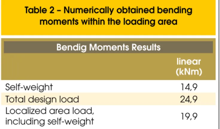
Tables 1 and 2 show, respectively, numerically obtained displace
-ment and bending mo-ments, within the deined region, for the three loading situations: slab weight only, total design load and, self-weight plus the experimental load.
Fig 3 shows numerically obtained vertical displacements, within the experimental loading area, for a uniformly distributed incre
-mental load applied on the whole slab. Also, Table 1, shows that the localized load (including self-weight) resulting displacement is 0.5 cm. Putting these information together, it can be determined, for the experimental load, an equivalent uniformly distributed load, applied in the whole slab, as far as displacements are concerned. This equivalent load corresponds to half of sum of permanent and accidental design loads. Such conclusion is shown in Fig 3, and Table 2 presents a similar idea regarding bending moments in the same region.
From the conclusion above, the deined experimental localized load was considered adequate for representing the wafle slab be
-havior in an experimental test.
Concrete was designed to achieve a compressive strength (fck) of
30 MPa at 28 days and a modulus of elasticity (E) of 26 GPa, both speciied in the original structure design. The clear cover was de
-ined according to Brazilian Code NBR 6118:2003 (ABNT, 2004). The adopted Poisson’s ratio was
ν
=
0
,
2
and the value used for reinforced concrete weight per unit volume was .The software design criteria used in this work were the same set by the original structure designer, as deined below.
2.2 CAD/TQS Main Design Criteria
TQS system offers the possibility of adopting some speciic design cri
-teria that allows the determination of efforts and reinforcement draw
-ing details accord-ing to the usual practice of the structural designer. The main design criteria adopted in this work are listed below.
n Restraint
The design criteria used for restraint in columns is called indepen-dent elastic restraint. In this case, each beam has a separate link to the column, deined by spring coeficients in the X and Y direc
-tions. These coeficients allow the reduction of clamping between beams and columns. The value adopted for the reduction coef
-icient was 4, which is the program default.
In addition to the springs in the X and Y directions, a spring in the Z direction may be introduced. The value adopted for re
-ducing the spring coeficient in Z direction was 1, which is the
program default.
n Plastiication on internal columns of wafle slabs
In intermediate columns, there are many ways to simulate plasti
-ication and to allow the consideration of torsion in the grid of the solid region around the columns. Thus, the bars inside the solid region are separated from the other ones, so that they could have more torsion and less lexure rigidity. The program extends the ribs into the solid region, completing the space between them with intermediate bars. The sum of the bar’s width in each direction is equal to the solid region width, and the edge-bars have a half width. The bars inside the solid region have a torsion inertia divi
-sor, while the edge-ribs may receive another divisor value. In this work, the torsion inertia divisor of the bars inside and outside of the solid region is the same and the value used was 6, which is the
program default.
Moreover, all bars in the solid slab region have their lexure inertia reduced by a parameter, simulating plastiication, which allows a better distribution of positive bending moments in the bars of the grid. This reduction parameter was taken as being equal to 1.6.
n Torsion in grillage
The CAD/TQS system allows considering torsion in grillage ribs, although this is not the default criteria of the software. In this work, torsion was supported only by the columns and edge-beams.
2.3 Numerical Results
After the necessary data has been provided, the software auto
-matically generated a numerical model of the slab, consisting on 1335 nodes and 2276 bars, as shown in Fig 4. The brown points indicate the localized area load.
2.3.1 Numerical Analysis for the localized area load, including the structure’s self-weight
the localized area load, including self-weight. These results were obtained from a linear analysis of the wafle slab.
Performed a non-linear analysis, to verify maximum vertical dis
-placements, it was obtained the results shown in Fig 7. The red lines represent bars in which the numerical analysis predicts cracking. TQS system does not allow performing any analysis without con
-sidering the structure’s self-weight. The experimental tests, howev
-er, measured vertical displacements only for the application of the localized area load, after the acting of the self weight. To compare such results, it was carried out an additional numerical analysis, considering only the slab self-weight. Thus, the desired numerical
results, concerning the effect of the localized area load only, could be obtained by the difference between both analyses.
2.3.2 Numerical Analysis considering only wafle slab self-weight
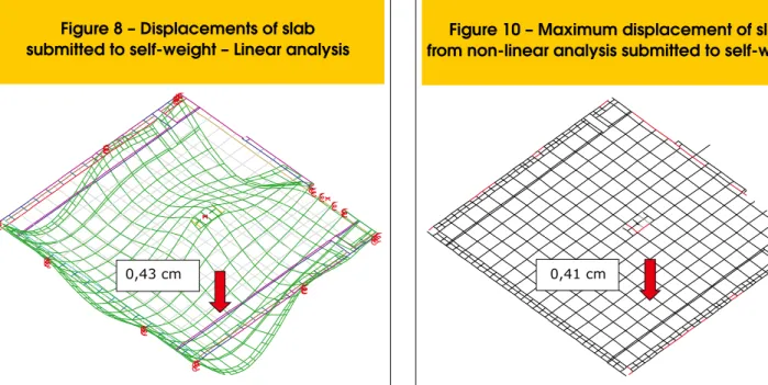
Fig 8 and 9 show, respectively, the deformed coniguration of the slab and the distribution of bending moments considering only the wafle slab self-weight. These results were obtained from a linear analysis of the slab.
of cracking in the grillage caused by self-weight. Interestingly, vertical displacements from the non-linear analysis result slightly lower then the ones obtained by linear analysis. This odd outcome resulted from the combination of two factors. The irst is that self-weight did not cause slab cracking and, therefore, no loss of stiffness. The second factor is that the non-linear analysis accounts for the presence of the reinforcement, which the linear does not, thus considering a more rigid structure.
3. Experimental Program
The experimental program was conceived aiming the measuring of strains and vertical displacements in some speciic sections of the
wafle slab, which was previously analyzed by a numerical model. The formwork was built with plastic cubes developed for wafle slabs
by Ulma Fôrmas e Escoramentos Ltda. This system is composed by
a modular supporting structure for the plastic cubes (Fig 11a), which is supported by metallic tubes that are very easily dismounted (Fig 11b). Reinforcement consisted of CA 50 and CA 60 steel bars, summa
-rized in Tables 3 and 4. The general position of the rib reinforce
-ment is found in Fig. 12. It can be observed that, in addition to posi
-tive and nega-tive reinforcement, the designer speciied a welded mesh, in CA 60 steel, for the top slab. This mesh was placed due to possible tension stresses in the top slab lower ibers, within the voids between the ribs.
Fig 13 shows the slab ready to be cast.
3.1 Instrumentation
Concrete strain gauges were placed in three cross-section of the structure. In each of those points, there were strain gauges in the top and in the bottom face (Fig 14).
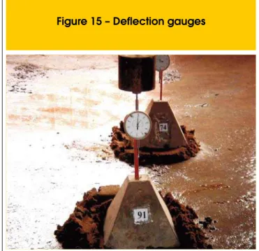
To measure vertical displacements, the wafle slab was instrument
-ed with 5 delection gauges. Those were ix-ed in concrete bases, leveled and positioned in the loor below (Fig 15). The position of instrumented points can be seen at Fig 16.
3.2 Wafle Slab Test
The test was performed 46 days after the structure’s casting and the load was applied in 4 steps, using cement bags, weighting 50 kg each (Fig 17).
At the end of each of the four loading and / or unloading steps, vertical displacements were measured by the delection gauges, and speciic strains obtained through a data acquisition system. Control specimen cylinders were cast along with the slab, to determine concrete’s modulus of elasticity (E) and compressive strength (fck). The
according to the standards of Brazilian Code NBR 8522:1984 (ABNT [11]). The average value obtained for three specimens was E=35,74 GPa. The concrete compressive strength at 28 days was determined from the compression test of the control specimens, according to the recom
-mendations of Brazilian Code NBR 5739:1994 (ABNT [12]). The value obtained for the concrete compressive strength was fck = 37,2 MPa.
4. Comparison between Test
and Numerical Results
The tested slab was numerically analyzed considering two sets of values for the parameters compressive strength (fck) and modulus of elasticity (E), the ones speciied by the structural designer and the obtained experimentally from the test specimens.
Numerical and experimental results were then compared, concern
-ing speciic strains and vertical displacements, in some speciic points showed in Fig 16.
4.1 Vertical Displacements
Figures 18 to 22 show experimentally measured vertical displace
-ments, compared to the numerical ones, obtained from the slab non-linear analyses considering both values for compressive strength (fck) and modulus of elasticity (E).
The slab presented a near linear behavior under crescent loading and test results were very close to the numerical ones. Instrument
-ed points 1 and 2, show-ed displacements close to the numerical predictions when adopting the experimental modulus of elasticity. On the other hand, points 3, 4 and 5, agreed more closely with nu
It is noticed that delection gauges 3, 4 and 5 presented some re
-sidual results during unloading, which may indicate a beginning of cracking in the area after total loading, However, the slab did not show any visual signs of cracking.
4.2 Speciic Strain
The numerical values for speciic strains were obtained from the bending moment results. For such calculation, the section mo
-ments of inertia were determined considering the presence of the reinforcement, for both cracked and uncracked cross-section, ap
-plying the Transformed Cross-Section Method (PARK [13]) Table 5 shows the calculated values of strains, in concrete and at the reinforcement, for cracked and uncracked sections and for both modulus of elasticity, determined according to recommenda
-tions of Brazilian Code NBR 6118:2003 (ABNT [6])
Figs 23 to 28 present the comparison between numerical and ex
-perimental strains, for each load stage in all instrumented points.
-all uncracked behavior, in accordance with the results of the
just developing under the total load, but not yet imposing a crack
-ing like behavior for the whole structure. That was also indicated by the numerical analysis.
Figs 23 and 24 indicate the presence of bending stresses in top slab, within the voids between ribs, thus conirming the adequacy of the welded steel mesh speciied by the design engineer.
5. Final Conclusions
The presented results showed that the wafle slab under study be
-haved in a linear like fashion during the loading process, indicating no overall cracking, but only in some localized areas, as numeri -cally predicted.
It was also observed that the measured vertical displacements and strains were satisfactorily close to the numerically predicted ones, indicating an adequate response of the numerical model used in the analysis.
6. Acknowledgements
The authors gratefully acknowledge to CNPq, to Projetak – Tava-res Eng. Associados S/C Ltda and to Maiojama Participações for
their support to this work.
7. References
[01] DIAS, R. H. Análise Numérica de Pavimentos de Edifícios em Lajes Nervuradas. Dissertação (Mestrado em Engenharia) – Escola de Engenharia de São Carlos, Universidade de São Paulo (USP), São Carlos, 2003.
[02] PEREIRA, V. F. Projeto de lajes treliçadas armadas em duas direções. Artigo Técnico. Disponível em: http://www.ufes.br/~ctjr/outeng/artigos/art4.pdf. Acesso em 06/12/2003.
[03] MONTOYA P.J.; MESEGUER A.G.;CABRE,F.M. Hormigón armado. 10 ed. Barcelona: Editorial Gustavo Gili, S. A., [197-].
[04] AJDUKIEWICZ, A.; STAROLSKI, W. Reinforced-concrete slab-column stuctures. New York: Elsevier Science Publishers, 1990.
[05] SELISTRE, S. L.C. Análise Teórico-Experimental de uma Laje Nervurada de Microconcreto Submetida a um Carregamento Uniformemente Distribuído. Dissertação (Mestrado em Engenharia) – Curso de Pós-Graduação em Engenharia Civil, Universidade Federal do Rio Grande do Sul, Porto Alegre, 2000. [06] ABDUL-WAHAB, H. M. S.; KHALIL, M. H. Rigidity and Strength of Orthotropic Reinforced Concrete Wafle Slabs. Journal of Structural Engineering, v. 126, n. 2, Feb., p. 219-227, 2000.
[07] SOARES, Y.V. Análise Experimental de Lajes Cogumelo Nervuradas de Concreto Armado com Pilares Metálicos. Dissertação (Mestrado em Engenharia) – Curso de Pós-Graduação em Engenharia Civil, UFSC, Florianópolis, 2003.
[08] SCHWETZ, P. F. Análise teórico-experimental de uma laje nervurada modelo reduzido sujeita a um
carregamento linear. Dissertação (Mestrado em Engenharia) – Curso de Pós-Graduação em Engenharia Civil, UFRGS, Porto Alegre, 2005. [09] TQS Informática Ltda. (a) . Sistemas Computacionais
– Engenharia Estrutural: CAD/Formas. São Paulo, s.d. várias paginações.
[10] ASSOCIAÇÃO BRASILEIRA DE NORMAS TÉCNICAS. NBR 6118:2003 : Projeto e Execução de Obras de Concreto Armado. Rio de Janeiro, 2004.
[11] ASSOCIAÇÃO BRASILEIRA DE NORMAS TÉCNICAS. NBR 8522:1984 : concreto – determinação do módulo de deformação estática e diagrama – tensão de deformação – Método de ensaio. Rio de Janeiro, 1984. [12] ASSOCIAÇÃO BRASILEIRA DE NORMAS TÉCNICAS.
NBR 5739:1994 : concreto – ensaio de compressão de corpos de prova cilíndricos. Rio de Janeiro, 1994. [13] PARK R.; PAULAY T. Reinforced Concrete Structures.