A ield investigation of load-induced delections using a FWD device allowed evaluating the joint behavior of plain jointed concrete pavements regarding its load transfer eficiency (LTE) at joints. Such parameter, at non dowelled joints, present a large variation along day hours as well as along the seasons (winter and summer); while dowelled joints disclosed little variation for LTE with values ranging from 90 to 100%, non dowelled joints have reduced trans-fer eficiency between 50% (winter) to 60% (summer). Using FEM-based software it was allowed to estimate very similar values, matching the ield data, conirming the requirements for considering LTE behavior at joints during structural analysis and design of concrete pavements.
Keywords: joints; plain concrete pavements; load transfer.
Medidas de delexões com o falling weight delectometer permitiram a avaliação do comportamento de juntas em pavimentos de concreto simples do ponto de vista de sua eiciência de transferência de cargas (LTE). As investigações mostraram importantes variações nesse parâmetro, quando não há dispositivos de transferência de cargas, entre horários de dias bem como entre estações climáticas distintas (inverno e verão); enquanto que juntas com barras de transferência apresentam, pouca variação nesse parâmetro e encontrando-se em geral entre 90 e 100% de capacidade de transferência, quando há quedas de temperatura, as juntas sem barras chegam a apresentar capacidade de transferência reduzida para 50% no inverno e para 60% no verão. Valores estimados de transferência de carga com um programa de elementos initos permitiram conirmar a necessidade de tratamento teórico do problema em fases de análise estrutural e projetos de pavimentos de concreto com juntas.
Palavras-chave: juntas; pavimentos de concreto simples; transferência de carga.
Effects of temperature changes on load transfer in plain
concrete pavement joints
Efeito das variações de temperatura na transferência
de cargas em juntas de pavimentos de concreto
G. M. COLIM a [email protected]
J. T. BALBO b [email protected]
L. KHAZANOVICH c [email protected]
a Rua Bogotá, nº 148 – Setor Anhanguera, Araguaína – TO - CEP: 74.817-510
b Escola Politécnica da USP, Departamento de Engenharia de Transportes, [email protected], Av. Prof. Almeida Prado 83, travessa 2, CEP 05516-000, Cidade Universitária, São Paulo, Brazil.
c University of Minnesota at Twin Cities, Department of Civil Engineering, 500 Pillsbury Drive S.E., Minneapolis, 55455-0116, USA.
Abstract
1. Introduction
Almost all types of concrete pavement in slab systems have joints with the exception of pavements with continuous reinforcement, whose joints, when occur, are only constructive ones. In addition, shrinkage cracks can be seen as joints. The joints are cross-sec-tional and longitudinal and in both cases, load transfer occur be-tween side or successive slabs when a load is approaching to this joint, whether or not there is effort transmission element. There may be load transfer due to dowel bars; however, in the absence of that, yet load transfer occurs by interlock effect between ag-gregates in particular when it is a contraction joint. This friction mechanism and shear in concrete adjacent vertical faces may also occur either in construction joints or between pre-fabricated slabs in equal or lesser scale (Figure [1]).
The load transfer effect consideration in concrete pavement joints is essential in design and structural analysis whether new or in old loor restoration. Through these effects is that horizontal stresses imposed in structural system, next to these joints, can be drastically reduced, which is a positive fact in determining project resistance for concrete, reinforcement rates, slab thickness and structural re-inforcements. The smaller or larger load transfer eficiency is de-pendent on the system temperature (joint opening), the modulus of subgrade reaction and the joint type (contraction with or without load transfer, construction or expansion bars). The effective mea-sure of load transfer effects can be done, experimentally, by using two techniques. In the irst one, the pavement is instrumented with
strain gages and load cells that allow to measure deformations in
concrete and pressure on lower layers by approaching a moving load to a joint; however, this procedure is expensive, which will be take into account as an alternative technique. The vertical defor-mations can be measured on the concrete surface (delections), in two opposite positions, orthogonally and also away from the joint, when the load is applied in one of positions [1]. With performing load transfer, the discharged slab move d2 in a more or less
sym-pathetic way to the charged slab d1 moving, thus allowing the de-termination of an arbitrarily named parameter for the load transfer eficiency (from English load transfer eficiency – LTE), according to equation [1]:
(1)
[%]
100
1 2
´
=
d
d
LTE
By equation [1], if the charge transfer is null, the delection in the discharged slab is also null, in which case only the charged slab undergoes deformation. When LTE reaches 100%, the load trans-fer is the highest, such that the vertical deformations on both slabs must be identical. When one consider that the structure response in the joint should not be dependent only on the previously men-tioned transfer elements, even though the joints were completely without contact, throughout the slab depth, any transfer would hap-pen through lower layers [2] and assuming that LTE extreme val-ues would require a great distance between the joint faces, which would be more palpable in the case of expansion joints.
Based on the exposed concepts, it is to be expected that LTE af-fects the performance of concrete pavements as well as seasonal changes over time. According to the American Concrete Pavement Association [3], the LTE value must not be less than 75% for a
provided load transfer, by a joint, to be considered appropriated. Concrete pavement calculation methods that are current adopted in the country such as the one in São Paulo City Hall [4], an oficial method, and according to the Portland Cement Association
guide-line [5], a non-oficial method, they do not consider explicitly the LTE value and its seasonal nuances. Thus, determined stresses values in the design can distance from the ield reality, where LTE varies with climatic conditions to which pavements are exposed. In the absence of such studies in wet tropical climate, it is essential that some research be undertaken to establish load transfer
load transfer eficiency and durability, Colley and Humphrey [11] used three subgrade types in their study: clay, gravel and a ce-ment-treated base. With an opening in the joint of 0, 89 mm and on the clay subgrade, comparing the two different thicknesses slabs (180 and 280 mm), the load transfer eficiency was 5% for the thin-ner and 29% for the thicker slab. Clearly, the thicker slab rigid-ity contributed to the pavement resistance on this subgrade type. Concerning to granular basis, the eficiency increased for 9% and 50% respectively. And it increased even more on cement-treated base. They also concluded that the higher the joints’ opening, the lower system load transfer eficiency.
Vandenbossche [12] found that the load transfer eficiency in con-crete pavement slabs of new plain concon-crete pavement without BT in the joints may vary between 70 and 100%. LTE in new pave-ments with BT varies between 80 and 100%. The Federal Highway Administration [13] recommends that the concrete pavement
res-toration, used to prevent future damage, should occur when one of the following conditions is checked: the 3 mm joint scaling or cracking or more; LTE less than 70%; difference between delec-tion in the loaded slab are greater than 0.25 mm in the unloaded slab; and joint scaling and cracking accumulation above extension of 525 mm/km.
2.2 Temperature and Joint Opening
Shahin [1], based on LTE measurements in plain concrete pave-ments joints at airports in the U.S., suggests that the joint load transfer can be adjusted according to temperature or time of the day, as the LTE values that occur at the beginning in the morning are lower than those veriied at the end of the day due to concrete expansion. The following function with the correction factor (F) is proposed to be held this correction in the LTE value (known only a LTE value makes possible the LTE determination for any time of the day):
(2)
(
1
)
100
[%]
1
2
´
+
´
=
F
LTE
d
d
This correction factor is given graphically for certain periods of pavement measurements. This template indicates an F decrease between 8am and 2pm, and F is null after this period for the 2pm reference time. The LTE determination for the 2pm is performed by the equation [2] based on LTE measurement for any time, de-termining the correction factor for this measurement time. F values are calibrated based on ield measurements of prevailing condi-tions in USA northeastern (temperate climate).
The concrete temperature, resulting in its expansion or contrac-tion, interferes with the joint opening along the pavement service life. The load transfer eficiency is drastically reduced with the joint opening increase [14]. Thus, the joint opening should be as small as possible, which transfer bars, and in pavements with continuous reinforcement it may be controlled more effectively.
A study to understand the effect of the different concrete pavement characteristics in relation to the joints opening used twelve test sections built in Chillicothe, Ohio, with several slabs’ lengths, types of bases, types of dowel bars and joint sawing modes [15]. The pavement had two lanes 3.6 m wide and 230 mm CCP slab thick-terns in transverse joints of plain concrete pavements. Work of this
nature will enable updating and improvement of sizing methods for LTE changes consideration over the project service-life, which means admitting differentiated structural answers of pavements over time, which is an inexorable fact. It was the goal in this article to describe experiments that were done by characterizing LTE val-ues in different climatic conditions, taking into account the effect of cemented and granular bases in plain concrete pavements at contraction joints, with and without dowel bars.
2. Main aspects on load transfer
The irst record of dowel bar is from 1918, used in plain concrete pavement, in Newport News, Virginia [3]. Friberg [6] indicated that
dowel bars should be of plain steel with 600 mm length and circular diameter of 19 or 22 mm on most highways, and should be spaced 300-500 mm; besides that, half bar should be greasy not to adhere to the concrete. However, until 1970s and 1980s, many roads and corridors were built without dowel bars in many countries, including the USA, but this was unusual in Europe; as a consequence of this technique, the faulting in transverse joints with subsequent uneven edges break (faulted joints), were generally observed, damaging the users’ comfort. Khazanovich wrote about it [7]: “Many concrete pavements performance with joints have not been historically in-terpreted by its structural capacity, but rather by its joint system...
Mediocre values of load transfer eficiency lead to occurrence of longitudinal and corner cracks, in addition to expressive delection
in the joints. These defects may lead to the presence of irregularity and poor bearing conditions.”
It was found in a poll conducted in North America [7] that only between the 1970s and 1990s almost the totality of States and provinces were required to build concrete pavements with dowel bars. It is noted that, even in the USA, the understanding process of dowel bars in joints to improve the long-term performance of concrete pavements date back to around two or three decades ago. It is clear then the existing technical dichotomy for traditional users of concrete pavements such as Germany, Austria and Swit-zerland, where since the 1930s the use of dowel bars on highways was not dispensed [8]. In a recent study in the laboratory [9] tests were performed to assess the structural behavior of transverse joints in simple concrete slabs with reduced dimensions in relation to conventional pavements; the concrete slab thickness ranged as well as the imposed loading, in addition to several devices of load transfer being tested. The results allowed noting that the BT use in concrete pavements makes the load transfer signiicantly higher than in the case of load transfer device absence. Of course, this affects the concrete pavement performance in operation.
2.1 Load Transfer Measures in Joints
Khazanovich and Gottif [10] declare that load transfer measures in joints from researches of Strategic Highway Research Program (SHRP) pointed out that LTE values range as smaller than 20%
and also near 100%. The measures were implemented also in slab cracks, trying to understand the damage effects on the same slab by means of checked load transfer. They concluded that approxi-mately 10% of the joints had LTE below 50% while the vast major-ity of cracks resulted in calculated LTE above 85%.
ness. For both bases were used both granular and stabilized materials with cement. In the study it was observed that the maximum horizontal movement of concrete slabs occurred in the months when the temperature widely varied between day and night, being related to temperature in the concrete with the horizontal displacements in the slabs. The study showed that the maximum movement (opening) occurs in colder months. This is evidence that the LTE at low temperature is lower due to concrete contraction. It was also verified that base type, whether it was granular or stabilized with cement, did not af-fect the joint opening, which is really important for structural analysis. This is indicative that the base use such as RCC (roller compacted concrete) or CTCS (cement treated crushed stone) would not restrict the slab movement differently from well-graded gravel or other granular bases.
Khazanovich and Gotlif [10] studied data from many road sec-tions within the LTPP/NHCPR program, including joint opening measures at different times of day and seasons, which did not exceed 2 mm, considered all roads’ sections.
For Vandenbossche [12], LTE in BT-free joints can decrease more than 50% when the opening is larger than 0, 9 mm. The author indicates that with tests using falling weight deflectom-eter (FWD), LTE values resulted in 50% in the morning and
90% in the afternoon. Greer [16] also obtained results show-ing change from 16 to 84% in LTE values in slabs without BT as temperature changes between winter and summer weeks. These changes were not significant when there was a load transfer device (BT) in the plain concrete slab joint.
In a Japan survey [17], it was developed a relational model between LTE and the joint opening for pavements with and without BT. The authors noted that in the case of BT presence, the opening has little influence on the LTE value compared to the case of concrete pavements without BT. The LTE value with BT decreased with the joint opening, tending asymptoti-cally the minimum value of 80%. It was also checked that slabs without BT, the LTE value falls linearly because of joint open-ing, tending to zero for an opening around 4 mm.
Field analysis were done in laboratory under PCA [11] to eval-uate the efficiency and durability of load transfer due to the aggregated interlocking in cracked concrete faces. Variables were then considered: the joint opening, foundation resistance, and load level and slab thickness. Two types of aggregates for concrete were used: well-rounded pebble and gravel stone with sharp edges. Regarding the joint opening, which ranged from 0.5 to 2 mm, it was verified that the higher the opening joint, the lower is its efficiency in load transferring.
Poblete et al. [18] determined that the maximum difference
be-tween joint opening at the top and bottom slab found in a plain concrete pavement in Chile was of 0.15 mm in pavements without BT. Pittman [19] observed that the joint opening width on the surface was statistically equal at the bottom of the crack.
2.3 Effects of reaction system for slab support
Regarding the subgrade reaction modulus (k) effects in the concrete slabs, analytical models like that of Westergaard [20]Table 1 – Experimental plain concrete pavement sections at USP
Section
Slab
Length
(m)
thickness (mm)
Slab
Base
type
thickness (mm)
Base
Dowels
A
A1
4.00
150
CS
200
In both joints
A2
5.50
150
CS
200
A3
7.50
150
CS
200
B
B1
4.00
150
RCC
200
In both joints
B2
5.50
150
RCC
200
B3
7.50
150
RCC
200
C
C1
4.00
250
RCC
100
In both joints
C2
5.50
250
RCC
100
C3
7.50
250
RCC
100
D
D1
4.00
250
CS
100
In both joints
D2
5.50
250
CS
100
D3
7.50
250
CS
100
E
E1
5.50
250
CS
100
Only between slabs
E1 and E2
E2
5.50
250
CS
100
and numerical, like that of Balbo [21], both using the concept of Winkler foundation, showed that variations of this parameter in concrete slab stresses is very small. However, works as of Spangler [22] based on experimental road clearly show that there are differences between this concept of subgrade reac-tion when a load is applied on slab edge or center. Shahin [1] in his analysis used the finite element method for load simula-tion applied in the concrete slab corner, determining LTE val-ues due to subgrade reaction modulus (k) and the maximum deflections obtained in the evaluated slabs, in a backcalcula-tion process. The results gave clear indicabackcalcula-tions that for the same deflection amount, the lower the value of modulus of subgrade reaction (k), the greater the load transfer (higher LTE). In other words, the load transfer descriptor parameters in the joints and in the pattern of support layers springy de-formability would work together in defining the deflections im-posed by the external loading.
Zollinger [23] presented results of an experiment in plain concrete pavements with different thicknesses of concrete slabs (200 to 360 mm) in order to analyze the joint opening in the concrete slab due to subgrade reaction module. The results indicated that for the same value of subgrade reaction modulus (k), the greater the thickness of the concrete slab, the greater should be the joint opening for the same deflec-tion. These results support the hypothesis that the structural parameters work together and are difficult to individualize in an evaluation, but different value combinations may result in similar effects.
3. Load transfer tests in experimental
concrete slabs
The concrete slab’s analysis in true greatness, regarding the load transfer in joints, was carried out in the existing experimental plain concrete pavement area at USP campus in São Paulo. The stud-ies’ details are presented as follows:
3.1 Delection Measures in experimental road
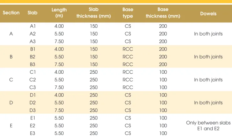
The road with experimental plain concrete pavement at USP has five sections with different structural characteristics for the
concrete slabs as indicated in Table [1]. The dowel bars are spaced among them by 300 mm; they have a 32 mm diameter (CA-25 Brazilian grade steel pattern) and 400 mm length. The pavement bases are made of plain graded crushed stone (CS) or of roller compacted concrete (RCC), all over an area with very homogeneous clay subgrade soil [24].
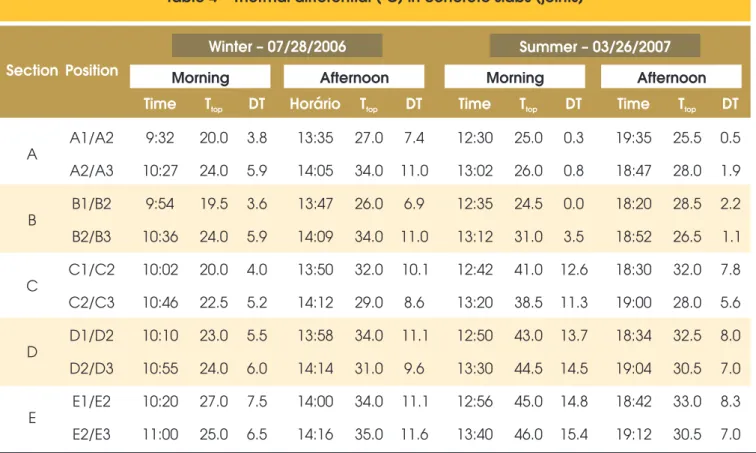
Tests with FWD (Figure [2]) were performed as described in Table [2], aiming to include two distinct seasons in São Pau-lo: winter (mild) and summer. Deflection measurements were made with seven sensors (geophones), one under the load application plate (this plate has 300 mm diameter). The top temperatures and values of thermal differences between top and bottom slab (calculated according to the defined empirical model in the proper experimental road [24]) are presented in Tables [3] and [4]. The applications of load on concrete pave-ment were performed with three load levels (approximately 47, 74 and 84 kN) to evaluate the effect of loading on the pave-ment structural parameters, each load being applied twice for results’ confirmation. The FWD load positioning was to 150 mm of joints, which used to guarantee the deflections’ mea-sures in this position as well as in the third geophone, 300 mm away from the load application center, so d1 and d3 were used to calculate LTE.
3.2 Initial estimate of structural parameters before
the backcalculation
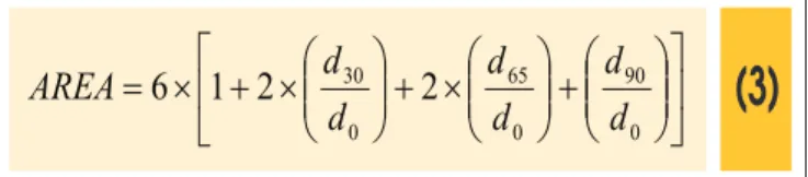
In order to obtain estimated start igures (seeds) for the parameters to be back analyzed, a proposed criterion by Hall [25] were used in which one determines the slab relative stiffness radius based on the delection basin area (AREA) according to the American
As-sociation of State Highway and Transportation Oficials (AASHTO [26]). This parameter is deined as follows:
(3)
ú
û
ù
ê
ë
é
÷÷
ø
ö
çç
è
æ
+
÷÷
ø
ö
çç
è
æ
´
+
÷÷
ø
ö
çç
è
æ
´
+
´
=
0 90 0 65 0 302
2
1
6
d
d
d
d
d
d
AREA
d0, d30, d65 e d90 delections are given in inches. With the AREA value, the relative stiffness radius (lk) from the equation:
(4)
387009 , 4559340
,
2
279133
,
1812
36
ln
ú
ú
ú
ú
û
ù
ê
ê
ê
ê
ë
é
-÷
ø
ö
ç
è
æ
-=
AREA
kl
For a semi-ininite slab with loading in its central region, it is pos-sible the analytical determination of the subgrade reaction modu-lus (k) once known the relative stiffness radius of the system, as proposed by Westergaard [20]:
(5)
ïþ
ï
ý
ü
ïî
ï
í
ì
÷÷
ø
ö
çç
è
æ
´
ú
û
ù
ê
ë
é
-+
÷÷
ø
ö
çç
è
æ
´
÷
ø
ö
ç
è
æ
+
´
´
´
=
2 2 025
,1
2
ln
2
1
1
8
k k ka
a
d
P
k
l
l
l
p
g
being k given in pounds per cubic inch, P the applied load (in
pounds-force), d0 the maximum delection at the slab center (in
inches), ℓk the relative stiffness radius given by equation [4] (in inches) and a the radius of the applied circular load by the FWD (in
inches). Known the relative stiffness radius values and subgrade reaction modulus, the elasticity modulus of the concrete slab (E) is calculated by the equation for determining ℓk, as Westergaard [20]:
(6)
( )
3 2 4 kh
1
k
12
E
=
´
´
l
-
m
where m is the Poisson coeficient of concrete and h is the thick-ness of concrete slab.
3.3 Backcalculation procedures of delection
basins by Finite Element Method
The backcalculation using the delection envelop data from ex-perimental slabs test track were carried out using the inite ele-ment method (FEM) program ISLAB2000 that allows numerical simulations of performed load tests in the ield, providing the evaluation of the modulus of elasticity of the concrete slabs as well as the subgrade reaction modulus and LTE parameter for the real ield conditions [27; 28]. In order to execute this back-calculation, 27.786 structural parameter simulations of studied concrete pavements were required (14.826 for the center load and 12.960 for the slab joint load). It is presented a simulation case of the mentioned program for joints without BT in Figure [3]; the inite element mesh for three successive slabs of an ex-perimental slab section is represented in this mesh.
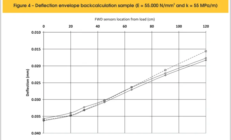
After the estimation of parameters E and k values by the cri-terion previously presented [25], they have been ixed as an extreme variation range for the backcalculation attempts for such parameters, a value below the lowest estimation and an-other value above of the highest estimation for the parameter in question. Within these ranges for the parameter combinations, simulations were performed, increasing the values and combin-ing them with the purpose to simulate the theoretical delection basin and compare them with measured basin in the ield. In Figure [4], a backcalculation of values for E and k is exempli-ied, systematizing the best theoretical delection basin (delec-tion envelope) found for the ield measurements obtained with FWD load over slab center A2. The closeness and acceptance
Table 2 – FWD measurements program
Season
Day
Period
Central
load
over joints
Loads
Targets and uses
Winter
2006
07/28/2006
morning
a
a
Concrete modulus
of elasticity
Subgrade modulus of reaction
(central and edge)
LTE
afternoon
-
a
Subgrade modulus of reaction
(central and edge)
LTE
Subgrade modulus of reaction
Summer
2007
03/26/2007
afternoon
-
a
(central and edge)
LTE
night
-
a
Subgrade modulus of reaction
(central and edge)
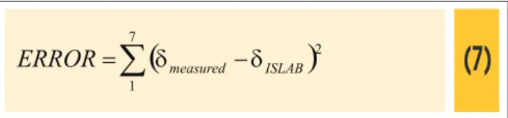
criterion between the backcalculated delection basin and that one measured in the ield was based on the calculation of the square error between the individual delections of both basins according to the expression:
(7)
(
)
å
-=
71
2
ISLAB measured
ERROR
d
d
The smallest square error of the simulation series indicates the theoretical basin that is closer to the real measured on the road. This process was carried out by successive approximations with the narrowing of parameter value range for each set of simula-tions. Such procedures and criteria above mentioned were also used for measured delection basin backcalculation in the joints’ vicinity of concrete slabs. In these cases, the values previously backcalculated of concrete modulus of elasticity (to slab center) were used, leaving the determination for the end process by backcalculation of the modulus of subgrade reaction values in the transverse edges (kb) and eficiency values of load transfer in joints (LTE).
4. Results and its analysis
The LTE values were calculated according to equation [1] where they were presented individually for each load in Table [5]. Of such individual values, it is clearly noted that the BT presence in the transverse joints results in a signiicant increase in the LTE amount compared to the case of joints without BT when the load transfer is done exclusively by the interlocking between faces of aggre-gates (compare any positions with position E3). This highlights the fact that concrete pavements with BT present better performance, which is explained by more relieved stress states arising from the BT presence in joints when the load requests the pavement in this position [7].
An important aspect to be taken into account from the results pre-sented in Table [5] is that there is an increase for LTE values cal-culated in slabs without BT (slab E3) due to load increase for the summer. There is no signiicant difference in BT slabs for these LTE values with different loading levels, in both winter and sum-mer. This does not mean that the delections do not change with load increasing. Based on this observation, the analyses that fol-low are done from the average values of all measures for the
ap-Table 3 – Thermal differentials in concrete slabs (center)
Section
FWD location
Time
Temperature
(ºC)
Thermal Differential
(DT in ºC)
A
A1
9:25
20.0
3.7
A2
9 45
:
21.0
4.2
B
B1
9 50
:
19.5
3.4
B2
9 57
:
19.0
3.2
B3
10 31
:
23.5
5.4
C
C1
10 00
:
20.0
3.7
C2
10 06
:
21.0
4.2
C3
10 40
:
22.0
4.7
D
D1
10 08
:
22.5
5.0
D2
10 12
:
23.0
5.2
D3
10 50
:
24.0
5.7
E
E1
10 16
:
28.0
7.8
E2
10 25
:
25.0
6.2
o
Table 4 – Thermal differential ( C) in concrete slabs (joints)
Section
Position
Winter – 07/28/2006
Summer – 03/26/2007
Morning
Afternoon
Morning
Afternoon
Time
T
topDT
Horário
T
topDT
Time
T
topDT
Time
T
topDT
A
A1/A2
9:32
20.0
3.8
13 35
:
27.0
7.4
12 30
:
25.0
0.3
19 35
:
25.5 0.5
A2/A3
10 27
:
24.0
5.9
14 05
:
34.0 11.0
13 02
:
26.0
0.8
18 47
:
28.0 1.9
B
B1/B2
9 54
:
19.5
3.6
13 47
:
26.0
6.9
12 35
:
24.5
0.0
18 20
:
28.5 2.2
B2/B3
10 36
:
24.0
5.9
14 09
:
34.0 11.0
13 12
:
31.0 3.5
18 52
:
26.5 1.1
C
C1/C2
10 02
:
20.0
4.0
13 50
:
32.0
10.1
12 42
:
41.0 12.6
18 30
:
32.0 7.8
C2/C3
10 46
:
22.5
5.2
14 12
:
29.0
8.6
13 20
:
38.5 11.3
19 00
:
28.0 5.6
D
D1/D2
10 10
:
23.0
5.5
13 58
:
34.0
11.1
12 50
:
43.0 13.7
18 34
:
32.5 8.0
D2/D3
10 55
:
24.0
6.0
14 14
:
31.0
9.6
13 30
:
44.5 14.5
19 04
:
30.5 7.0
E
E1/E2
10 20
:
27.0
7.5
14 00
:
34.0
11.1
12 56
:
45.0 14.8
18 42
:
33.0 8.3
E2/E3
11 00
:
25.0
6.5
14 16
:
35.0 11.6
13 40
:
46.0 15.4
19 12
:
30.5 7.0
2
Figure 4 – Deflection envelope backcalculation sample (E = 55.000 N/mm and k = 55 MPa/m)
0.010
0.015
0.020
0.025
0.030
0.035
0.040
0 20 40 60 80 100 120
FWD sensors location from load (cm)
D
ef
le
ct
io
n
(m
m
)
Deflection envelope for 1st load Deflection envelope for 2nd load ISLAB 2000 backcalculated deflection envelope
plied loads as shown in Table [6]. In all slab joints, with the excep-tion of E3 joint that does not have BT, the load transfer varies very little from morning to evening in the winter. When there isn´t a BT, LTE value increases during the afternoon, as it is clear for E3 slab (from 61.6 to 73.5%). These values are intermediate to those indi-cated by Vandenbossche [12] that would be of 50% in the morning and 90% in the afternoon.
The variations between morning and afternoon and evening and night, in general, are below ± 5 percentage points, exception made to B3 slab where this variance reaches 9 to 10 percentage points. But, a variation of 10 percentage points on a basic value of 90% means a variation at about 10% in LTE. In the case of E3 slab, there is a variation of 12 percentage points on an LTE of 62%, representing an increase of at about 20% in value. This result co-incides with those submitted by Shahin [1] which afirmed that in studies for slabs without BT, LTE values in the afternoon in relation to morning period ranged from 20% (positive variation). Just for the case of winter measures, it becomes apparent that in joints with dowel bars, the LTE values decrease from morning to after-noon without exceptions. Generally, this assertive is impaired, as in summer measures, this has not been veriied.
These facts are well elucidated in the graphical representation of Figure [5] for the winter of 2006 and summer of 2007. During the winter, in most cases of slabs with BT, the LTE does not vary or decreases a little bit in the afternoon, and when it decreases, there aren’t falls that result in inferior values less than 90% on average.
90% is taken as an excellent LTE value since the constructive sys-tem can present support deiciency in the joint vicinity, for example, reducing the LTE. However, it is noted appreciable fall in LTE value when there is no load transfer with BT, which was approximately of 95% (with BT) to 65% (without BT).
There is still an important load transfer in the case of E3 slab due to aggregate interlocking even in the absence of BT. In addition, the measures’ response is fairly consistent, because with the top temperature increase at about 10oC (see Table [4]) between the morning measure (11 am) for the afternoon measure (2 pm) in the slab E3, the LTE has increased; this means that the slab would have expanded and the joint opening, in consequence, decreased, which would cause greater interlocking between them, improving the load transfer, as it was observed in practice; in other words, there is an increase in the shear modulus of the joint interface by aggregate interlocking on this cracked surface. The conclusion is that during periods without solar radiation, when concrete re-sumes its original volume (construction) or contracts itself, LTE is expected to be lower even than that observed value for 11 am, in the case of BT absence in the joints. The LTE measured values in summer day, which also resulted in high values for joints with BT and reduced for joints without BT, didn´t undergo major changes over the winter.
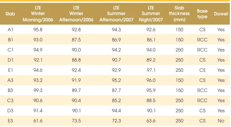
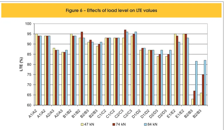
of delection values on the slab surface, individualizing what is the contribution of each layer. However, the obtained results would yet allow some speculations about the load transfer effects in differ-entiated situations about base type, slab thickness, as it is done in sequence. In Figure [6], LTE results are presented in relation to the applied loading level nearby slabs’ joints. It is noted that in joints
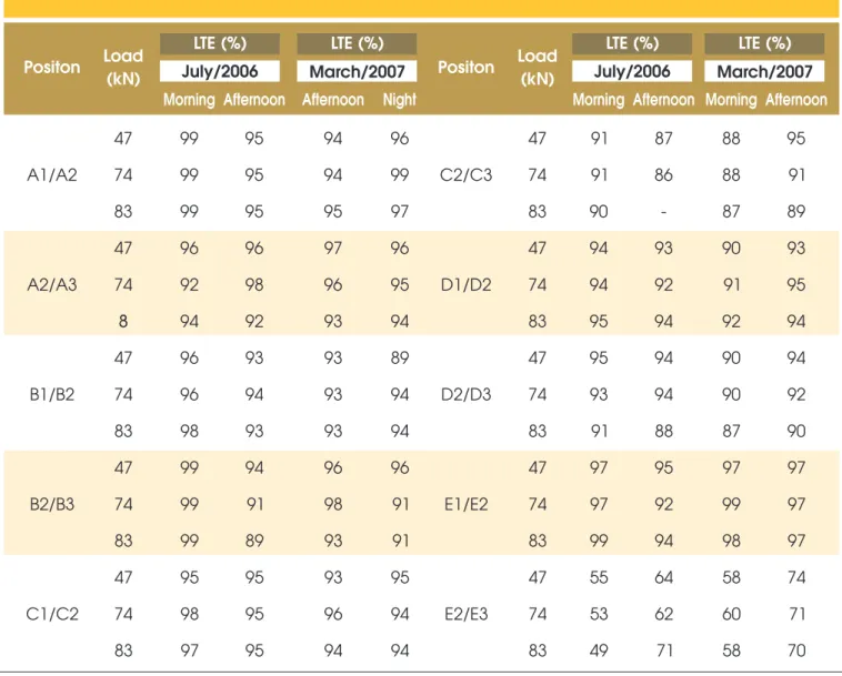
without BT the greater the applied load, the greater joint load trans-fer eficiency. In the case of slabs with BT in the joints, there aren’t marked differences between the applied load levels and LTE. In Table [7] are shown backcalculated values (with ILSAB 2000) for load transfer eficiency with tests that were performed in July, 2006 (winter) and in March, 2007 (summer). The backcalculated
Table 5 – LTE results (in %) with different FWD loads
Winter 2006
Summer 2007
Morning
Afternoon
Afternoon
Night
Position Slab
FWD load (kN)
FWD load (kN)
FWD load (kN)
FWD load (kN)
47
74
84
47
74
84
47
74
84
47
74
84
A1/A2
A1
95
96
96
93
93
93
95
94
94
93
92
92
A1
96
95
96
93
93
92
94
94
94
93
93
92
B1/B2
B1
95
93
92
90
87
87
88
87
87
87
86
85
B1
93
94
92
87
87
87
86
86
87
86
86
86
C1/C2
C1
94
94
94
91
89
89
95
94
94
94
94
94
C1
94
100
94
91
90
91
93
96
93
94
94
94
D1/D2
D1
94
92
90
89
88
88
91
92
91
88
89
89
D1
94
91
91
89
88
90
89
90
91
90
89
90
E1/E2
E1
95
94
95
92
94
92
93
93
93
97
98
97
E1
95
94
95
92
91
93
93
93
93
97
96
97
A2/A3
A3
93
94
94
91
92
92
93
97
96
96
96
96
A3
93
92
93
92
92
92
94
95
96
96
96
97
B2/B3
B3
100
100
100
92
90
90
87
88
88
96
96
96
B3
100
98
98
90
89
88
87
87
87
96
96
95
C2/C3
C3
91
91
91
93
92
88
84
85
87
88
90
89
C3
92
90
90
92
89
88
84
85
87
88
89
88
D2/D3
D3
92
91
91
91
89
90
95
94
91
89
90
89
D3
92
91
91
91
89
90
95
95
93
91
91
90
E3
62
63
63
77
74
72
63
67
82
62
65
68
E2/E3
Table 6 – Average results for LTE (%)
Slab
Winter
LTE
Morning/2006
LTE
Winter
Afternoon/2006
LTE
Summer
Afternoon/2007
LTE
Summer
Night/2007
Slab
thickness
(mm)
Base
type
Dowel
A1
95.8
92.8
94.3
92.6
150
CS
Yes
B1
93.0
87.5
86.9
86.1
150
RCC
Yes
C1
94.9
90.0
94.2
94.0
250
RCC
Yes
D1
92.1
88.8
90.7
89.2
250
CS
Yes
E1
94.6
92.4
92.9
97.1
250
CS
Yes
A3
93.2
91.9
95.2
96.0
150
CS
Yes
B3
99.3
89.7
87.7
95.9
150
RCC
Yes
C3
90.6
90.4
85.2
88.5
250
RCC
Yes
D3
91.4
90.1
94.4
90.1
250
CS
Yes
E3
61.6
73.5
72.3
63.6
250
CS
No
Figure 5 – LTE values for winter and summer
50 52 54 56 58 60 62 64 66 68 70 72 74 76 78 80 82 84 86 88 90 92 94 96 98 100
LTE (%)
A1 B1 C1 D1 E1 A3 B3 C3 D3 E3
LTE values in joints with BT for winter measures ranged between 90 and 99%, making it not possible to distinguish clearly effects of base type and concrete slab thickness. During the summer, these values varied between 86 and 99% again, so it is not possible to establish behavior patterns. All these values are typical of new pavements, which are justiied by the non-occurrence of commer-cial trafic in the experimental sections, placed at a parking lot for cars. In the case of joint without dowel bar, during the winter, in the morning, the LTE was appreciably lower than that one in the afternoon (around 50% vs. 70%). In the summer, such important variations between afternoon and evening have not been veriied, even because in this time of year the temperature amplitude is little than in the winter.
It is observed from the results that LTE values in dowelled joints ranged from 88 to 100%, while those obtained in non-dowelled joints ranged from 60 to 75%. In the Figure [7] such data are re-leased one due to another, which allows us to compare qualitative-ly the discrepancies between measured and backcalculated LTE values. It appears that for low LTE values (<80%) cases without BT, the LTE measured values are generally higher than those that were calculated. Differently in the case of LTE in joints with BT, the backcalculated values are mostly higher than those that were calculated. Based on the average of measured and backcalculated LTE values in the ield in joints with BT, as illustrated in Figure [8], it appears that the backcalculated LTE values are generally higher than the values measured in the ield, in joints with BT.
Calculating the average, standard deviation and coeficient of variation of ield measured and backcalculated LTE data, in the ield in joints without BT, illustrated in Figure [9], the opposite is veriied: measured LTE values in the ield are in general larger
than those backcalculated by ISLAB2000. It is also noted that the discrepancy between backcalculated and measured LTE values increases in periods in which the joint opening was greater: in the morning and at night. Thus, the ISLAB2000 program simulates critical conditions of load transfer (LTE lower values) for the same delection measurements in the ield and theoretically deined. This result corroborates with previous results using the ISLAB [29] program that indicated higher calculated stresses by the program than those with certain measures of road deformation, that is, the numerical model of ILSAB2000, in these conditions, presents the results in favor of security for project purposes. Backcalculation, however, permits its calibration for different uses.
However, the average backcalculated and measured LTE values in the ield are very close, not allowing greater differentiation in the results. Including the very low results shown for standard deviation and variation coeficient, especially for joints with BT (maximum standard deviation observed was 3.4%, quite positive for mea-sures taken in the ield), which allows good reliability on obtained results through used methodology. Such results are probably tied to great construction homogeneity of the experimental slabs. The values here obtained are inferior to those that were suggested by Khazanovich and Gotlif [10]: variation coeficient around 10% for joints with BT and 40% for joints without BT; despite the fact that the survey was much broader and contemplated different aged pavements, structures and concrete conditions in general. As Col-ley and Humphrey [11] evidenced the load transfer in joints without BT is extremely dependent on the joint opening; this opening es-sentially depends on the concrete average temperature. In colder periods, with the concrete contraction, the joints are opened, caus-ing the fallcaus-ing in the LTE value, which was visible in the present
Figure 6 – Effects of load level on LTE values
60 65 70 75 80 85 90 95 100
A1/A 2
A1/A 2
A2/A 3
A2/A 3
B1/B 2
B1/B 2
B2/B 3
B2/B 3
C1/C 2
C1/C 2
C2/C 3
C2/C 3
D1/D 2
D1/D 2
D2/D 3
D2/D 3
E1/E 2
E1/E 2
B2/B 3
B2/B 3
LT
E
(%
)
Table 7 – Backcalculated values for LTE
Positon
Load
(kN)
LTE (%)
LTE (%)
July/2006
July/2006
LTE (%)
LTE (%)
March/2007
Positon
Load
(kN)
March/2007
Morning
Afternoon
Afternoon Night
Morning
Afternoon
Morning
Afternoon
A1/A2
47
99
95
94
96
C2/C3
47
91
87
88
95
74
99
95
94
99
74
91
86
88
91
83
99
95
95
97
83
90
-
87
89
A2/A3
47
96
96
97
96
D1/D2
47
94
93
90
93
74
92
98
96
95
74
94
92
91
95
83
94
92
93
94
83
95
94
92
94
B1/B2
47
96
93
93
89
D2/D3
47
95
94
90
94
74
96
94
93
94
74
93
94
90
92
83
98
93
93
94
83
91
88
87
90
B2/B3
47
99
94
96
96
E1/E2
47
97
95
97
97
74
99
91
98
91
74
97
92
99
97
83
99
89
93
91
83
99
94
98
97
C1/C2
47
95
95
93
95
E2/E3
47
55
64
58
74
74
98
95
96
94
74
53
62
60
71
83
97
95
94
94
83
49
71
58
70
study. Such variations should be rigorously considered in design to forecast possible periods of critical stresses close to joints.
5. Conclusions
Based on the investigations and conducted experimental analysis, it is possible highlight and to conclude that:
n The individual LTE values shows that the dowel presence in
the transverse joints results in a signiicant increase in its value in comparison to the case of joints without BT;
n The LTE values in non-dowelled slabs showed increase due to
load intensiication during and for the summer;
n There isn’t any signiicant difference for LTE values in slabs
with dowels at different levels of loading, both in the winter and in the summer;
n In all slab joints with dowels, the load transfer ranges just a little
from morning to afternoon in winter;
n For the non-dowelled joint the LTE value increased during the
afternoon as well as they were bigger in the summer (due to concrete expansion and increased aggregate interlock within joint lateral faces);
n The LTE values range in dowelled joints at about 10% average
between afternoon and evening;
n The LTE values range in non-dowelled joints at about 20%
av-erage between afternoon and evening;
n It is noted, however, appreciable fall in LTE value when there
is no load transfer with dowel, which was approximately of 95% to 65% (without dowel).
Based on well planned back analysis with ISLAB2000 program, it can also be concluded that:
n The back analyzed LTE values in doweled joints for winter
measures ranged between 90 and 99%, it is not possible to distinguish clear effects of concrete slab thickness base type. During the summer, such values ranged between 86 and 99% again, not being possible to establish behavior patterns;
Figure 7 – Comparison of backcalculated and measured LTE values for doweled joints
40
50
60
70
80
90
100
40
50
60
70
80
90
100
Backcalculated LTE
M
ea
su
re
d
LT
E
Winter/Morning Winter/-Afternoon Summer/Afternoon Summer/Night
Figure 8 – Comparison of backcalculated and measured LTE values for doweled joints (by season)
88
90
92
94
96
98
100
Winter/morning
Winter/Afternoon Summer/Afternoon
Summer/Night
LT
E
(%
)
Backcalculated LTE
Measured LTE
the LTE was appreciably lower than that one in the afternoon (around 50% vs. 70%);
n For low LTE values (< 80%), case without dowel, measured
LTE values are generally superior to those ones that were cal-culated. Differently, in the case of LTE in joints with dowels, the
backcalculated values are mostly superior to those that were calculated.
n The average of back analyzed and measured LTE values in the
Figure 9 – Comparison of backcalculated and measured LTE values for joints without dowels
40
45
50
55
60
65
70
75
80
Winter/morning
Winter/Afternoon Summer/Afternoon
Summer/Night
LT
E
(%
)
Backcalculated LTE
Measured LTE
The obtained results pointed out the need for explicit consideration of LTE variations in the behavior of concrete slabs without dowel bars for paving, because according to the time of day or season, effort transfers in joints changes a lot, which causes variations in the distribution of stresses in these project critical elements.
5. Acknowledgments
The scholarship of the main author was supported by the National Council for the Scientiic and Technological Development of the Brazilian Ministry for Science and Technology. Authors are also grateful to the Sao Paulo State Foundation for Research whose support allowed the construction of the experimental concrete pavements.
7. References
[01] SHAHIN, M. Y. Use of the falling weight delectometer for the non-destructive delection testing of jointed concrete airield pavements. In: Proceedings, 3rd International Conference on Concrete Pavement Design and Rehabilitation, Purdue University, pp. 549–556, 1985.
[02] PEREIRA, D. S.; BALBO, J.T.; KHAZANOVICH, L. Theoretical and ield evaluation of interaction between ultra-thin whitetopping and existing asphalt pavement. International Journal of Pavement Engineering, vol.7, no. 4, pp. 251-260, 2006. [03] AMERICAN CONCRETE PAVEMENT
ASSOCIATION. Effect of pavement surface type on fuel consumption. Skokie, 1989.
[04] PREFEITURA DO MUNICíPIO DE SãO PAULO. Design of Concrete Pavements (in Portuguese). IP-07/2004, São Paulo, 2004.
[05] PORTLAND CEMENT ASSOCIATION. Thickness design for concrete hightway and street pavements. EB109P, Skokie, 1984.
[06] FRIBERG, B. F. Load and delection characteristics of dowels in transverse joints of concrete pavements. Transactions of the American Society of Civil Engineers, vol. 105, pp. 140-161, 1938. [07] KHAZANOVICH, L. Execução de juntas e
transferência de cargas em pisos de concreto: controvérsias e fatos reais. Tradução: José Tadeu Balbo. Revista Concreto & Construções, Instituto Brasileiro do Concreto, no. 45, ISSN 1809-7197, pp.15-18, São Paulo. 2007.
[08] JACKSON, F.H.;ALLEN, H. (1948) Concrete pavements on the German autobahen. Journal of the American Concrete Institute, vol. 20, n. 4, pp. 933-976, Detroit.
[09] RODRIGUES, L. F.; PINHEIRO, L. M.; GUINAMãES, G. N. Joints in plain concrete pavements: an
experimental study of load transfer mechanisms. Proceedings of the International Workshop on Best Practices for Concrete Pavements (Cd-rom), Brazilian Concrete Institute, Recife, 2007.
[10] KHAZANOVICH, L.; GOTLIF, A. Evaluation Of joint and crack load transfer. Final Report, Federal Highway Administration, FHWA-RD-02-088, Washington, D.C., 2003.
de Agregados em Juntas de Pavimentação de Concreto de Cimento Portland. 2º Simpósio sobre Pesquisas Rodoviárias, Rio de Janeiro, Brasil, 1966. [12] VANDENBOSSCHE, J. M. Effects of slab
temperature proiles on the use of falling weight delectometer data to monitor joint performance and detect Voids. In: Transportation Research Board Annual Meeting, Compendium of papers (Cd-rom), Washington, D. C., 2007.
[13] FEDERAL HIGHWAY ADMINISTRATION. Pavement rehabilitation manual. FHWA-ED-88-025, Washington, D.C., 1990.
[14] ZOLLINGER, D. G.; BARENBERG, E. J. A Mechanistic based design procedure for jointed concrete pavements. In: Proceedings, 4th International Conference on Concrete Pavement Design and Rehabilitation, Purdue University, pp. 75–97, 1989. [15] BODOCSI, A.; MINKARAH, I. A.; ARUDI, R. S.
Analysis of Horizontal Movements of Joints
and Cracks in Portland Cement Concrete Pavements. In: Transportation Research Record nº 1392, pp. 43-52. TRB, National Research Council, Washington, D.C., 1993.
[16] GREER W.C..Evaluation of Strength Tests and Acceptance of Concrete Pavements. Proceedings: Fourth International Conference on Concrete Pavement Design and Rehabilitation, Purdue University, 1989, pp. 375-383.
[17] NISHIZAWA, T.; SHIMENO, S; KOMATSUBARA, A.; KOYANAGAWA, M. Study on thermal stresses in continuously reinforced concrete pavement. In: Transportation Research Record nº 1629, TRB, pp. 99-107, Washington, D.C., 1989. [18] POBLETE, M., VALENZUELA, R.; SALSILLI R.
Load transfer in undoweled transverse joints of PCC pavements. Transportation Research Record 1207, Washington, D. C, 1988.
[19] PITTMAN, D. W. Load transfer characteristics of roller-compacted concrete pavement joints and cracks. In: Transportation Research Record nº 1525, TRB, pp.01-09 Washington, D.C., 1996.
[20] WESTERGAARD, H. M. Analysis of stresses in concrete pavements due to variations of temperature. In: Proceedings of the 6th Annual Meeting of the Highway Research Board, pp. 201-215, Washington, D.C., 1926.
[21] BALBO, J. T. Application of the Finite Element Method on the Structural Analysis of Road Concrete Pavements. Master Thesis
(in Portuguese). Escola Politécnica da Universidade de São Paulo, São Paulo,1989.
[22] SPANGLER, M.G. Stresses in corner region of concrete pavements. Bulletin 157, Engineering Experiment Station, Iowa State College, Ames, 1942. [23] ZOLLINGER, D. G. Curing and inishing concrete
pavements. Proceedings of the International
Workshop on Best Practices for Concrete Pavements. Brazilian Concrete Institute and International Society for Concrete Pavements, Recife, (Cd-rom), 2007.
[24] BALBO, J. T.; SEVERI, A. A. Thermal gradients in concrete pavements in tropical environment: an experimental appraisal. In: Transportation Research Record nº 1809, TRB, pp.12-22, Washington, D.C., 2002. [25] HALL, K. T. Performance, Evaluation, and
Rehabilitation of asphalt-overlaid concrete pavements. Ph.D. thesis. University of Illinois at
Urbana-Champaign, 1991.
[26] AMERICAN ASSOCIATION OF STATE HIGHWAY AND OFFICIALS. Guide for design of pavement structures. Washington, D.C., 1993.
[27] KHAZANOVICH, L. Structural analysis of multi-layered concrete pavement systems. Ph.D. Thesis, University of Illinois, Urbana, IL. 1994. [28] KHAZANOVICH, L.; YU, H.T.; RAO, S.; GALASOVA
K.; SHATS E; JONES R. ISLAB2000 - Finite element analysis program for rigid and composite pavements. User’s Guide. Champaign, IL: ERES Consultants. 2000.