ISSN 0104-6632 Printed in Brazil
www.abeq.org.br/bjche
Vol. 30, No. 03, pp. 413 - 435, July - September, 2013
Brazilian Journal
of Chemical
Engineering
INVESTIGATION OF HEAT TRANSFER
PROCESSES INVOLVED LIQUID
IMPINGEMENT JETS: A REVIEW
M. Molana and S. Banooni
*Department of Mechanical Engineering, Engineering Faculty, Phone: 0098 (662) 5304043, Fax: 0098 (611) 336-9684, Shahid Chamran University, Ahvaz, Iran.
E-mail: [email protected]
Department of Mechanical Engineering, Engineering Faculty, Phone: +98 (912) 3885209, Fax: 0098 (611) 336-9684, Shahid Chamran University, Ahvaz, Iran.
E-mail: [email protected]
(Submitted: April 28, 2012 ; Revised: July 18, 2012 ; Accepted: July 27, 2012)
Abstract - This review reports research on liquid impingement jets and the abilities, limitations and features of this method of heat transfer. Some available and important correlations for Nusselt number are collected here. Also we demonstrate the capability of nanofluids to be applied in heat transfer processes involved liquid impingement jets.
Keywords: Liquid impingement jet; Nanofluid; Heat transfer; Nusselt number.
INTRODUCTION
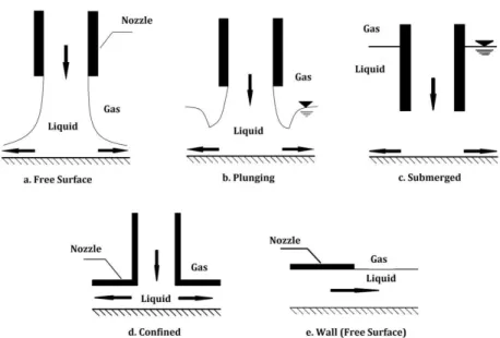
Impinging jets can be classified as either free-surface or submerged. Submerged jets exude into a space containing the same liquid at rest and can be configured as confined or unconfined, depending on the jet-to-target distance. In a submerged configuration, the interaction of the issuing jet and the stagnant fluid leads to entrainment in the shear zone and the development of a potential core near the jet center-line. The potential core is the region in which the velocity of the jet remains largely unaffected by the spreading of the jet due to entrainment (Webb and Ma, 1995). In the confined case, the fluid heated by the target plate can, in some instances, get re-circulated and be entrained back into the impinging jet. This causes the formation of a re-circulation zone in the outflow region (Fitzgerald and Garimella, 1998). In an unconfined configuration, such as the case when jets are issuing from long tubes, the jet
interacts with the ambient and otherwise quiescent surroundings and has associated with it higher heat transfer coefficients because the heated fluid is not entrained back into the jet, as is sometimes the case for confined jets (Lupton et al., 2008). The point at which jets differentiate between fully confined and fully unconfined will likely depend on many factors, including but not limited to Re, H/d and surface topology. Although this has not been fully charac-terized, some progress has been made (Lupton et al., 2008).
Figure 1: Different types of impingement jets.
The magnitude and distribution of the heat transfer coefficient has been found to be dependent on a number of parameters, including Prandtl number (Pr), Reynolds number (Re), jet-to-target spacing (H/d), jet diameter (d) and the physical geometry of the jets and heater surface (Martin, 1977), (Jambunathan et al., 1992). Compared to single jet impingement, the heat transfer and flow characteristics of jet arrays have received much less attention in the open literature, although some works exist (Goldstein and Timmers, 1982).
The primary advantage of arrays of multiple jets is the creation of multiple stagnation zones with sometimes exceptionally high local heat transfer coefficients. Depending on aspects such as jet to jet spacing and cross flow conditions, high local surface heat transfer coefficients can be maintained over the entire surface. This can result in very high surface average heat transfer coefficients and more uniform surface temperature distributions, which is a particu-larly desirable property of an electronics cooling package. The use of impinging jets as an interesting method of heat removal is one area receiving some consideration. Impingement jets have already found extensive use in industrial applications for purposes such as the thermal treatment of metals and the cooling of turbine blades (Schutt, 2007; Bunker, 2007) solar collectors, oil jets in oil cooled internal combustion engines (Kiryo, 1986), water jets in the hot rolling process of steel (Kohing, 1985), medical cryosurgery of cancers (Aihara and Kim, 1993), X-ray devices and military transient cooling in rocket nozzles (Kandlikar, 1998) and laser weapons (Mudawar and Wadsworth, 1991).
Banooni et al. (2008) studied heat transfer effects of an impingement jet on baking of flat bread. They concentrated on some important parameters such as jet velocity variation, jet temperature, jet to target distance and quality properties of bread as target. They demonstrated clearly the desirability of using impingement jets in baking, because of heat transfer uniformity and better quality properties of bread. Therefore, this heat transfer approach is a promising method in food processing.
The popularity of impingement jet systems de-rives from the fact that they possess one of the highest known single phase heat transfer coefficients. A few studies reviewed heat transfer of impingement jets and their applications (Polat et al., 1989), (Jones and Launder, 1972). In this study, we concentrate on works related to liquid impingement jets and their applications for cooling and heating in recent years. Also we focus on the types of the jets and their effects on the heat transfer coefficient.
HYDRODYNAMICS OF LIQUID IMPINGEMENT JETS
circular disk as target). The second zone is the impingement region, where the interaction between the jet and the heated target produces a strong deceleration of the flow. After this zone, the liquid wets and flows in a direction parallel to the target.
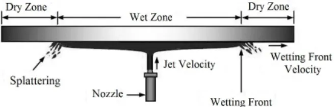
The difference between liquid and gas impinge-ment jets is that, when a turbulent liquid jet impinges on a flat target, a spray of droplet breaks off from the liquid layer formed on the target. This splattering of droplets lowers the efficiency of the impingement jet heat transfer cooling process due to the loss of liquid. The laminar jets do not splatter. When the jet turbu-lence is sufficiently large, these waves sharpen and break into droplets. All observations indicate that the amplitude of the disturbance on the jet governs splattering (Varella and Leinhard, 1991). It should be noted that the amount of splattering at a given nozzle to target spacing depends principally on the jet Weber number. Also, the surface tension of the liquid plays an important role in splattering (Bhunia, 1993). A liquid impingement jet is shown in Figure 2.
Figure 2: Liquid impingement jet
When a liquid is first impinged on the hot surface, it remains stagnant in a small impingement region for a certain period of time before covering the entire surface. This time period varies from a fraction of a second to a few minutes, which depends on the experimental conditions. This wetting delay period is described as the residence time, t*, in the present study. The local wall temperature at the stagnation radius at the residence time is represented by Tw* in this study. Figure 3 describes the above mentioned definition of quenching phenomena by using a cooling curve. Just after the residence time, the wetting front starts moving and consequently the surface temperature drops at a faster rate. Before the residence time, the surface temperature drops slowly and almost at a constant rate though there is a sudden drop of temperature at the very beginning of the jet impingement.
Some studies (Liu et al., 1991; Leinhard et al., 1972) also performed on free surface jet impinge-ment cooling, have given valuable background information on single phase convection heat transfer.
Wetting delay is an important phenomenon in jet impingement quenching. A number of comprehen-sive reviews on jet impingement are available in the literature (Cooper et al., 1993; Amano and Brandt, 1984).
Figure 3: Cooling curves during quench for copper
block T0 = 350 °C, Tliq = 51 °C, uj = 3 m/s (reprinted
from Woodfield et al. (2005), with permission from Elsevier).
SINGLE LIQUID IMPINGEMENT JETS
This type of impingement jets have been investi-gated extensively numerically, experimentally and theoretically by many researchers and scientists for different applications. Watson (1964) solved the hydrodynamic problem of the impact of a liquid jet over a horizontal plane analytically.
In the experiment by Carper and Deffenbaugh (1978) a nozzle diameter of 0.2 cm was used for Reynolds number ranging from 200 to 400, a nozzle diameter 0.4 cm was used for Reof 400 to 1000 and for Re of higher than 1000 a nozzle diameter of 0.8 cm was used. They compared their results with predictions from using Watson’s solution. It must be mentioned that they concluded Nusselt number did not depend on the nozzle diameter. The Watson’s analytical solution predicts Nusselt number that are in good agreement with experimental results for a nozzle diameter of 0.4 cm in the range of Re = 400 to 1000. The results from using a nozzle diameter of 0.2 cm are lower and for a nozzle diameter of 0.8 cm the Nusselt numbers are higher than the Watson’s solution.
divided into four regions of flow along heat transfer surfaces, including a stagnation zone and three wall jet zones, from which general expressions for the heat transfer coefficients were obtained. Further-more, those results were compared with experimen-tal and analytical data available in the published literature. Good agreement was observed from the comparisons.
Patel and Roy (2001) researched jet impingement heat transfer for varying fluid flow characteristics and concluded that:
Heat transfer is maximum through the shear layer formed near the jet attachment stagnation region. For all Reynolds numbers, the maximum Nusselt number for the closed boundary condition is higher than for the open boundary condition. This is primarily because more energy is lost in the open boundary condition than in the closed adiabatic boundary conditions.
Turbulence (velocity gradient) and wall shear force are higher in the shear layer region and highest at the stagnation point.
The average Nusselt number grows as the Reynolds number increases.
The objective of Lallave et al.’s (2007) study was to characterize the conjugate heat transfer for a confined liquid jet impinging on a rotating and uni-formly heated solid disk of finite thickness and radius. The model covered the entire fluid region (impinging jet and flow spreading out over the rotating surface) and the solid disk as a conjugate problem. It was found that plate materials with higher thermal conductivity maintained a more uni-form temperature distribution at the solid–fluid interface. A higher Reynolds number increases the local heat transfer coefficient reduced the wall to fluid temperature difference over the entire interface. The rotational rate also increases the local heat transfer coefficient under most conditions. The simulation results compared reasonably well with previous experimental studies. They concluded that the solid–fluid dimensionless interface temperature, the local Nusselt number and the local heat transfer coefficient show a strong dependence on the follow-ing parameters: Reynolds number, rotational rate, impingement height, disk thickness, solid material properties, and fluid properties. Increasing the Reynolds number increases the local heat transfer coefficient distribution values over the entire solid– fluid interface. Simultaneously, this effect reduces the solid–fluid temperature and improves the cooling effectiveness of the process.
Miller et al. (1995) performed a numerical study on non-circular jets. They simulated the performance
of different geometries such as elliptic, rectangular and triangular jets with different aspect ratios.
Direct Numerical Simulation (DNS) of an un-steady impinging jet were performed by Chung et al. (2002) to study momentum and heat transfer characteristics. The unsteady compressible Navier-Stokes equations were solved using a high-order finite difference method with non-reflecting boundary conditions. It was found that the impingement heat transfer was very unsteady and the unsteadiness was caused by the primary vortices emanating from the jet nozzle. These primary vortices dominate the impinging jet flow as they approach the wall. Detailed analysis of the instantaneous flow and temperature fields was performed, showing that the location of primary vortices significantly affects the stagnation Nusselt number.
Thermochromic liquid crystals have been extensively applied to natural convection flows for the visualization of temperature and induced velocity fields. In a study by Ashforth-Frost and Rudel (2002), a single submerged impinging water jet was artificially seeded with microencapsulated liquid crystals. A nozzle to plate spacing of three nozzle diameters and a turbulent Reynolds number of 35500 was considered. Using liquid crystals as particle tracers had been demonstrated to be a useful tool for the simultaneous quantitative visualization of flow and temperature in a forced convection flow. Despite the hysteresis effects observed in the calibration of thermo-chromic liquid crystals, they have been demonstrated as a useful tool for gaining simulta-neous insight into the hydrodynamic and thermal flow features of a turbulent impinging jet.
Teamah and Farahat (2003) studied heat transfer from impinging of a single free liquid jet and ob-served that, from the results obtained either numeri-cally or experimentally, both local and average Nusselt numbers were higher in the shooting flow region than in the streaming flow region. This is because the fluid film thickness is very small in that region compared with the outer region. This means that the mean velocity of the fluid in that region is higher. It was also found from the comparison of the numerical and experimental results for single jet that there is a good agreement between them. Both the local and average Nusselt numbers increase with increasing Reynolds number.
decreased the Nusselt number slightly. Correlations for the local and average Nusselt numbers revealed an approximate Nusselt number dependence on the Reynolds number raised to the third power.
Poh et al. (2005) investigated the effect of flow
pulsations on the time-averaged Nusselt number for axis-symmetric semi-confined laminar impinging water jets. In that study, it was found that the onset of separation in the wall jet region of the pulsating impinging jet is associated with the point of constant Nusselt number during the oscillation cycle. This is attributed to the existence of vortices above that location, which tend to suppress the flow accelera-tion and deceleraaccelera-tion phenomena during oscillaaccelera-tion.
Conjugate heat transfer from a uniformly heated spinning solid disk of finite thickness and radius during a semi-confined liquid jet impingement from a rotating nozzle was studied by Rahman et al. (2008), who concluded that,
A great disk thickness provides a more uniform interface temperature and heat transfer coefficient. A reduction in the plate to disk confinement ratio increases the local Nusselt number at all locations. A higher Prandtl number fluid leads to a thinner thermal boundary layer and provides a more effective heat removal rate at the solid - fluid interface. Zuckerman and Lior (2006) performed a compre-hensive study on jet impingement heat transfer. They presented an interesting viewpoint in this area, including some disadvantages of impingement cool-ing devices, as follow:
For moving targets with very uneven surfaces, the jet nozzles may have to be located too far from the surface. For jets starting at a large height above the target, the decay in kinetic energy of the jet as it travels to the surface may reduce average Nu by 20% or more.
The hardware changes necessary for implement-ing an impimplement-ingimplement-ing jet device may degrade structural strength (one reason why impinging jet cooling is more easily applied to turbine stator blades than to rotor blades).
In static applications where very uniform surface heat or mass transfer is required, the resulting high density of the jet array and corresponding small jet height may be impractical to construct and implement, and at small spacings jet-to-jet interaction may degrade efficiency.
MULTIPLE LIQUID IMPINGEMENT JETS
Robinson and Schnitzler (2007) conducted experiments investigating the impingement of water
jet arrays under both free-surface and submerged conditions. In this work, a large population of jets was used, which induces cross flow which is known to influence the heat transfer (Obot and Trabold, 1987). Jet diameters of 1 mm were used, with a jet-to-jet spacing range of 3<s / D<7. Heater surface-averaged heat transfer and pressure drop data were recorded for a dimensionless jet-to-target distance range of 2<H / D<30 and a Reynolds number range of 650<ReD <6500. For the submerged jets, it was found that heat transfer was insensitive to jet-to-target distance changes in the range of
2<H / D<3. A uniform decrease in heat transfer was observed with increasing jet-to-target distance in the range of 5<H / D<20. It was reported that, for a constant Reynolds number, increasing the jet-to-jet spacing resulted in a detrimental effect on heat transfer. A stronger dependence on jet-to-jet spacing was encountered for smaller jet-to-target spacing. Free-surface jets were observed to behave as submerged jets within the range of 5<H / D<20. Beyond this value, entirely free jet flow occurs, with the heat transfer coefficient showing marginal improvement with increasing jet-to-target distance. At a jet-to-target spacing below H / D=3 the confined-submerged jets provided higher heat transfer coefficients for lower pumping power cost compared with free jets. It was also noted that, under confined-submerged conditions, decreasing the inter-jet distance, and therefore increasing the number of jets, decreased the pumping power requirement for a given heat transfer coefficient.
Royne and Dey (2006) investigated the effect of nozzle geometry on the heat transfer and pressure drop of confined-submerged jet arrays. Four different geometries were investigated with sharp-edged nozzles. These results were attributed to their respec-tive favorable and unfavorable discharge coefficients. With regards to heat transfer for a given pumping power, it was reported that the sharp-edged and contoured nozzles both experienced enhanced performances in comparison to the conventional straight nozzle arrays. The sharp-edged nozzle array decreased the flow rate required for a given heat transfer, while the countersunk nozzle required an increased flow rate at a reduced pressure drop.
flow cell independent of the other jets. Hence, the heat transfer over the area of the flow cell is the same as for single jet impingement and the only effect of more jets is to decrease the amount of non-stagnation cooling. This result was confirmed by the work of Pan and Webb (1995).
Liquid jet and spray impingement cooling were studied experimentally and compared in the non-boiling regime by Oliphant et al. (1998). For the commercial nozzle and experimental conditions used in the present study, spray cooling demonstrated a strong dependence on mass flux and it was proposed that droplet velocity also affected the heat transfer. The results show that jet velocity plays a significant role in impingement cooling. For a given liquid mass flux and jet array configuration (e.g., the seven-jet configuration), an increase in velocity increased the heat transfer rate. However, comparing the seven- and four-jet configurations at the same jet diameter and liquid mass flux, the heat transfer coefficient was larger for the four-jet configuration. The decrease in the number of jets would be expected to decrease the average heat transfer, since less of the surface is exposed to the high transport region in a stagnation zone.
The decrease in the number of jets at a fixed mass flux, however, is offset by an increase in the jet velocity due to the reduction in total orifice area. The net effect is an increased average heat transfer. This indicates that there is a tradeoff between more jets and a greater stagnation region area (with its associated high transport) and higher velocities for better stagnation point cooling. One possibility is to reduce the diameter of the jets as their number is increased so that the velocity remains unchanged. This would provide high stagnation point heat transfer over the entire surface. The optimization of liquid jet array variables is considered in detail by Maddox and Bar-Cohen (1994).
The pitch pjet, or center-to-center positioning of
jets in an array, determines the degree of jet interaction. For jets spaced at a pitch-to-diameter ratio of pjet/D<4, the jets show significant interaction.
San and Lai (2001) showed that, for H/D=2, the interference persisted up to spacings of pjet/D=8 or
10 and the maximal Nu occurred at pjet/D=8.
A cooling device based on jet impingement was proposed for cooling of densely packed photovoltaic cells under a high concentration. The device consists of an array of jets where the cooling fluid is drained around the sides in the direction normal to the
surface. It is shown by Royne and Dey (2007) that the inherently non-uniform heat transfer distribution of jet arrays had little effect on the expected electri-cal performance of the PV array. They compared their results to Martin’s model and found good agreement. They also proposed a model which pre-dicts the pumping power required for an average heat transfer coefficient for different device configura-tions. The model predicts that a higher number of nozzles per unit area will perform better than a lower number of nozzles. It also predicts an optimal nozzle diameter for a given area and number of nozzles.
In another interesting study done by Wang et al. (2004), micromachined liquid jets were employed for cooling of VSLI chips. This study presents the design and fabrication of single-jets and multijet arrays with circular orifice diameters ranging from 40 to 76 m, as well as integrated heater and temperature sensor test devices. They used three jet arrays to investigate heat transfer performance. A removal of 90 W was demonstrated using a four-jet array at a flow rate of 8 ml/min with a 100 °C temperature rise with jet diameters of 76 µm. Boiling heat transfer coefficients of approximately 3 W/cm2 C and a wall superheat of 30°C in the experiments suggested the possibility of pool boiling. However, reducing the wall superheat and achieving higher heat removal rates requires visualization of the flow regimes and optimization of the flow rates to reduce flooding of the reservoir. Furthermore, optimization of the geometry is needed to minimize the large pressure drops in the jet formation process and alternate geometries, such as square, elliptical, and slot orifices, and optimal orifice lengths and orifice to impingement plane spacing should be explored to increase heat removal rates.
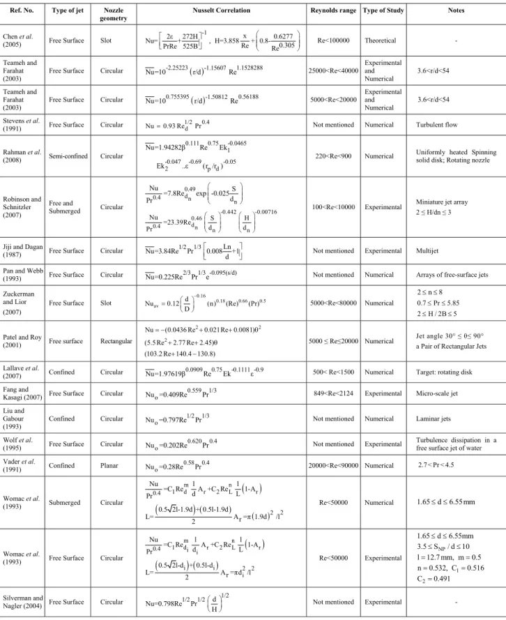
Table 1: Correlations for Nusselt number in liquid impingment jet systems
Ref. No. Type of jet Nozzle geometry
Nusselt Correlation Reynolds range Type of Study Notes
Chen et al.
(2005) Free Surface Slot
-1 x
2ε 272H 0.6277
Nu= + , H=3.858 +
0.8-0.305 Re
PrRe 525B Re
⎛ ⎞
⎡ ⎤ ⎜ ⎟
⎢ ⎥ ⎜ ⎟
⎣ ⎦ ⎝ ⎠ Re<100000 Theoretical -
Teameh and Farahat (2003)
Free Surface Circular Nu=10-2.25223( )r/d-1.15607Re1.1528288 25000<Re<40000
Experimental and Numerical 3.6<r/d<54 Teameh and Farahat (2003)
Free Surface Circular Nu=100.755395( )r/d-1.50812Re0.56188 5000<Re<20000
Experimental and Numerical
3.6<r/d<54
Stevens et al.
(1991) Free Surface Circular
1/2 0.4 d
Nu=0.93 Re Pr Not mentioned Numerical Turbulent flow Rahman et al.
(2008) Semi-confined Circular
0.111 0.75 -0.0465 1 -0.047 -0.69 -0.05
.
2 p d
Nu=1.94282 Re Ek
Ek .ε (r /r )
220<Re<900 Numerical Uniformly heated Spinning solid disk; Rotating nozzle
Robinson and Schnitzler (2007)
Free and
Submerged Circular
0.49 d
0.4 n
n
Nu S
=7.8Re exp -0.025
d Pr ⎛ ⎞ ⎜ ⎟ ⎜ ⎟ ⎝ ⎠ -0.442 -0.00716 0.46 d
0.4 n n n
Nu S H
=23.39Re d d Pr ⎛ ⎞ ⎛ ⎞ ⎜ ⎟ ⎜ ⎟ ⎜ ⎟ ⎜ ⎟ ⎝ ⎠ ⎝ ⎠
100<Re<10000 Experimental Miniature jet array 2 ≤ H/dn ≤ 3
Jiji and Dagan
(1987) Free Surface Circular
1/2 1/3 Ln
Nu=3.84Re Pr 0.008 +1
d
⎡ ⎤
⎢ ⎥
⎣ ⎦ Not mentioned Experimental Multijet Pan and Webb
(1993) Free Surface Circular
2/3 1/3 -0.095(s/d)
Nu=0.225Re Pr e Not mentioned Numerical Arrays of free-surface jets
Zuckerman and Lior (2007)
Free Surface Slot
0.16
0.18 0.66 0.5 av
d
Nu 0.12 (n) (Re) (Pr) D
−
⎛ ⎞ = ⎜ ⎟
⎝ ⎠ 5000<Re<80000 Numerical
2≤ ≤n 8 0.7≤ ≤Pr 5.85 2≤H / 2B≤5
Patel and Roy
(2001) Free surface Rectangular
2 2
2
Nu (0.0436 Re 0.021Re 0.0081)
(5.5 Re 2.77 Re 2.45)
(103.2 Re 140.4 130.8)
= − + + θ
+ + θ
+ −
5000 ≤ Re≤20000 Numerical Jet angle 30° ≤θ≤ 90° a Pair of Rectangular Jets Lallave et al.
(2007) Confined Circular
0.0909 0.75 -0.1111 -0.9
Nu=1.97619 Re Ek ε 500< Re<1500 Numerical Target: rotating disk
Fang and
Kasagi (2007) Free Surface Circular
0.559 1/3 o
Nu =0.409Re Pr 849<Re<2124 Experimental Micro-scale jet
Liu and Gabour (1993)
Confined Circular 1/2 1/3 o
Nu =0.797Re Pr Not mentioned Numerical Laminar jets
Wolf et al.
(1995) Free Surface Circular
0.620 0.4 o
Nu =0.202Re Pr Not mentioned Experimental Turbulence dissipation in a free surface jet of water
Vader et al.
(1991) Confined Planar
0.58 0.4 o
Nu =0.28Re Pr 20000<Re<90000 Numerical 2.7 < Pr < 4.5
Womac et al.
(1993) Submerged Circular
( )
(
)
( ) ( )m n
1 d r 2 L r 0.4
2 2
Nu l l
=C Re A +C Re 1-A
d L
Pr
0.5 2l-1.9d + 0.5l-1.9d
L= A =r π 1.9d /l
2
Re<50000 Numerical 1.65≤ ≤d 6.55mm
Womac et al.
(1993) Free Surface Circular
( )
(
)
( )m n
1 d r 2 L r 0.4 i i
i i 2 2
i
Nu l l
=C Re A +C Re 1-A
d L
Pr
0.5 2l-d + 0.5l-d
L= A =r πd /l
2
Re<50000 Experimental NP
1 2
1.65 d 6.55mm
3.5 S / d 10
l 12.7 mm, m 0.5
n 0.532, C 0.516
C 0.491 ≤ ≤ ≤ ≤ = = = = = Silverman and
Nagler (2004) Free Surface Circular
1/2 1/2 1/2 d
Nu=0.798Re Pr
H
⎛ ⎞ ⎜ ⎟
⎝ ⎠ Not mentioned Experimental -
Continuation Table 1
Ref. No. Type of jet Nozzle geometry
Nusselt Correlation Reynolds range Type of Study Notes
Garimella and Rice (1995)
Confined
Submerged Circular
-0.11 -0.11 0.695 0.4 SNP lN
Nu=0.160Re Pr
d d
⎛ ⎞ ⎛ ⎞ ⎜ ⎟ ⎜ ⎟
⎝ ⎠ ⎝ ⎠ 4000<Re<23000 Experimental NP N
1.59 d 6.35mm
1 S / d 5
0.25 l / d 12
≤ ≤ ≤ ≤ ≤ ≤ Garimella and Rice (1995) Confined
Submerged Circular
-0.52 -0.05 0.773 0.4 SNP lN
Nu=0.164Re Pr
d d
⎛ ⎞ ⎛ ⎞ ⎜ ⎟ ⎜ ⎟
⎝ ⎠ ⎝ ⎠ 4000<Re<23000 Experimental NP
N
1.59 d 6.35mm 6 S / d 14 0.25 l / d 12
≤ ≤
≤ ≤
≤ ≤
Womac et al.
(1996) Submerged Circular
( )
(
)
( )m n
d r L r
0.4
e e
2 2 r
Nu l l
=C Re1 A +C Re2 1-A
d L
Pr
2L /2 -1.9d + L /2 -1.9d L=
2
A =Nπ(1.9d) /l
⎡ ⎤ ⎡⎣ ⎤⎦
⎣ ⎦ 5000<Re<200000 Experimental
Multiple jet NP
1 2
0.5 d 1.0mm 2 S / d 4 N 4 or 9 jets l 127 mm n 0.8, C 0.509 C 0.0363 ≤ ≤ ≤ ≤ = = = = = Churchill and Bernstein (1977) Confined Circular ( ) 4/5 1/2 1/3 5/8
1/4 2/3
0.62Re Pr Re
Nu=0.3+ × 1+
282000 1+ 0.4/Pr ⎡ ⎛ ⎞ ⎤ ⎢ ⎜ ⎟ ⎥ ⎝ ⎠ ⎢ ⎥ ⎡ ⎤ ⎣ ⎦ ⎢ ⎥ ⎣ ⎦
Not mentioned Numerical
convection from gases and liquids to a circular cylinder in crossflow
Zhang and Hu
(2005) Confined Circular ( )
0.4884 1/3 -0.0043 o
Nu =1.215Re Pr L/D Not mentioned Experimental Target: curved surface
Sun et al.
(1998) Free Surface Circular
-0.5 o v -2/3 -1/6 3 o v v
Nu/Nu =0.777(r/d) for 1<r/d<r /d
25.7
Nu/Nu =1.85Re (r/d) +0.857
Re : r/d>r /d,r /d=0.177Re
⎡ ⎤
⎢ ⎥
⎣ ⎦ Re<100000 Experimental -
Lallave Cortes
(2009) Free Surface Circular
0.385 -0.091 0.4 0.0114 0.25 .
av
Nu =Re Ek .Pr . .ε− 445<Re<1800 Numerical
Spinning target
5 4
2.2 10 Ek 2.65 10
Pr 5.49, 0.55 5.0
227.6 697.5
− −
× ≤ ≤ × = ≤ β ≤
≤ ε ≤
Lallave Cortes
(2009) Free Surface Circular
0.3875 -0.091 0.25 0.01 .
av
Nu =1.965Re Ek .ε− .Fo 500<Re<110 Numerical
5 4
6.62 10 Ek 2.65 10 2.67, Pr 5.49 227.6 ε 697.5, 0.031 Fo 0.504
− − × ≤ ≤ × = = ≤ ≤ ≤ ≤ Lallave Cortes
(2009) Confined Circular
1.26 -0.1111 2.58 -0.5 0.65 av
Nu =Re .Ek .Pr− . .ε− 750<Re<2000 Numerical
Spinning target,
5 4
6.62 10 Ek 2.65 10 Pr 5.49, 0.55 5.0 227.6 697.5
− −
× ≤ ≤ ×
= ≤ β ≤
≤ ε ≤
Lallave Cortes (2009)
Spinning
Confined Circular
-0.01 0.75 av
-0.111 -0.05 0.69
. n .
Nu =1.9762. .Re Ek .(b/d ) ε−
500<Re<1500 Numerical
Stationary Target,
5 4
n
4.25 10 Ek 1.06 10 0.25 5, Pr 5.49 0.25 b/d 1.67 227.6 ε 627.6
− − × ≤ ≤ × ≤ ≤ = ≤ ≤ ≤ ≤ Lallave Cortes (2009) Stationary Partially Confined Circular 0.1 0.75 av
0.1 0.7 -0.05 . . p d
Nu =1.94282 .Re
Ek− .ε− (r /r )
360<Re<900 Numerical
Spinning Target,
4 4
p d
1.06 10 Ek 4.25 10 0.25 1, Pr 5.49 0.2 r /r 0.75 227.6 ε 627.6
− − × ≤ ≤ × ≤ ≤ = ≤ ≤ ≤ ≤ Lallave Cortes (2009) Spinning
Confined Circular
-0.01 0.75 -0.0465 . 1 av
-0.047 0.69 -0.05 .
2 p d
Nu =1.94282 .Re Ek
.Ek .ε− (r /r )
360<Re<900 Numerical
Spinning Target,
4 5
4 5
p d
4.25 10 Ek1 7.08 10 4.25 10 Ek2 7.08 10 0.25 1, Pr 5.49 0.2 r /r 0.75 227.6 ε 627.6
− − − − × ≤ ≤ × × ≤ ≤ × ≤ ≤ = ≤ ≤ ≤ ≤
Continuation Table 1
Ref. No. Type of jet Nozzle geometry
Nusselt Correlation Reynolds range Type of Study Notes
Lallave Cortes (2009)
Partially
Confined Circular
-0.01 0.74 -0.1 . av
-0.05 -0.05 -0.01 .
n p d
Nu =1.94282 .Re Ek
.(b/d ) (r /r ) .Fo
225<Re<900 Numerical
Spinning Target,
5 4
p d p d
7.08 10 Ek 4.25 10 0.25 1, Pr 5.49 0.2 r /r 0.75 0.2 r /r 0.75, 0.045 Fo 0.72 227.6 ε 376.7
− − × ≤ ≤ × ≤ ≤ = ≤ ≤ ≤ ≤ ≤ ≤ ≤ ≤ Fujii and Fujii
(1976) Confined Circular
( )
1/5 *
c,s 1/2 c
1/5 Pr
Nu = Gr Pr
4+9Pr +10Pr
⎛ ⎞
⎜ ⎟
⎜ ⎟
⎝ ⎠
Not mentioned Numerical -
Li and Garimella (2001)
Confined
Submerged Circular
0.266 0.071 0.513 0.441 e
av r
1.063 0.63 0.441 e
r D l
Nu 1.064 Re Pr .A
d d
D
1.291Re Pr .(1 A ) d − − − ⎛ ⎞ ⎛ ⎞ = ⎜ ⎟ ⎜ ⎟ ⎝ ⎠ ⎝ ⎠ ⎛ ⎞ + ⎜ ⎟ − ⎝ ⎠ 4000<Re<23000 Experimental e
1.59mm d 6.35 7.1 Pr 25.2 1 H / d 5 0.25 l / d 12 D 11.28mm ≤ ≤ ≤ ≤ ≤ ≤ ≤ ≤ = Sung and Mudawar (2008)
Free Surface Circular
jet 0.5 h jet 2 πDjet ch jet 0.199 4 jet jet 2 πDjet jet jet 4 D Nu
=63.41Re N jet p Pr
W D -+0.183Re N jet
phD
0.654 W
1 L - ch N D ph
0.654 2
+0.197Rejet Wch chH πDjet 1 1+
4 WchDjet
⎛ ⎞ ⎜ ⎟ ⎜ ⎟ ⎝ ⎠ ⎛ ⎞ ⎜ ⎟ ⎜ ⎟ ⎜ ⎟ ⎜ ⎟ ⎝ ⎠ ⎧ ⎡ ⎤⎫ ⎪ ⎢ ⎥⎪ ⎪ ⎢ ⎥⎪ ⎪ ⎢⎛ ⎞⎥⎪ ⎨ ⎢⎜ ⎟⎥⎬ ⎪ ⎢⎜ ⎟⎥⎪ ⎪ ⎢⎜ ⎟⎥⎪ ⎪ ⎣⎝ ⎠⎦⎪ ⎩ ⎭ ( )
{
0.654 0.654 0.654}
× 1 +2 +...+ N/2
1000<Re<3500
Experimental and Numerical
Hybrid cooling with N-nozzles: micro-channel flow and micro- jet impingement
Chen et al.
(2005) Free Surface Slot
-1
0.305
x
2ε 272H 0.6277
Nu= + , H=3.858 +
0.8-Re
PrRe 525B Re
⎛ ⎞
⎡ ⎤ ⎜ ⎟
⎢ ⎥
⎣ ⎦ ⎝ ⎠ Re<100000 Theoretical -
Teameh and Farahat (2003)
Free Surface Circular Nu=10-2.25223( )r/d-1.15607Re1.1528288 25000<Re<40000
Experimental and Numerical 3.6<r/d<54 Teameh and Farahat (2003)
Free Surface Circular Nu=100.755395( )r/d-1.50812Re0.56188 5000<Re<20000
Experimental and Numerical
3.6<r/d<54
Stevens et al.
(1991) Free surface Circular
1/2 0.4 d
Nu=0.93 Re Pr Not mentioned Numerical Turbulent flow Rahman et al.
(2008) Semi-confined Circular
0.111 0.75 -0.0465 -0.047 .
1 2
-0.69 -0.05 p d
Nu=1.94282 Re Ek Ek .ε (r /r )
220<Re<900 Numerical uniformly heated spinning solid disk; rotating nozzle
Robinson and Schnitzler (2007)
Free and
Submerged Circular
0.49 d
0.4 n n
Nu S
=7.8Re exp -0.025
d Pr ⎛ ⎞ ⎜ ⎟ ⎜ ⎟ ⎝ ⎠ -0.442 -0.00716 0.46 d
0.4 n n n
Nu S H
=23.39Re d d Pr ⎛ ⎞ ⎛ ⎞ ⎜ ⎟ ⎜ ⎟ ⎜ ⎟ ⎜ ⎟ ⎝ ⎠ ⎝ ⎠
100<Re<10000 Experimental Miniature jet array 2 ≤ H/dn ≤ 3
Jiji and Dagan
(1987) Free surface Circular
1/2 1/3 Ln Nu=3.84Re Pr 0.008 +1
d
⎡ ⎤
⎢ ⎥
⎣ ⎦ Not mentioned Experimental Multijet Pan and Webb
(1993) Free surface Circular Nu=0.225Re2/3Pr1/3 -0.095(s/d)e Not mentioned Numerical arrays of free-surface jets
Zuckerman and Lior (2007)
Free surface Slot
0.16
0.18 0.66 0.5 av
d
Nu 0.12 (n) (Re) (Pr)
D
−
⎛ ⎞
= ⎜ ⎟⎝ ⎠ 5000<Re<80000 Numerical
2≤ ≤n 8
0.7≤Pr≤5.85
2≤H / 2B≤5
Continuation Table 1
Ref. No. Type of jet Nozzle geometry
Nusselt Correlation Reynolds range Type of Study Notes
Patel and Roy
(2001) Free surface Rectangular
2 2
2
Nu (0.0436 Re 0.021Re 0.0081)
(5.5 Re 2.77 Re 2.45)
(103.2 Re 140.4 130.8)
= − + + θ
+ + θ
+ −
5000 ≤ Re≤20000 Numerical Jet angle 30° ≤θ≤ 90° a Pair of Rectangular Jets Lallave et al.
(2007) Confined Circular
0.0909 0.75 -0.1111 -0.9
Nu=1.97619 Re Ek ε 500< Re<1500 Numerical Target: rotating disk
Fang and
Kasagi (2007) Free Surface Circular
0.559 1/3 o
Nu =0.409Re Pr 849<Re<2124 Experimental Micro-scale jet
Liu and Gabour
(1993) Confined Circular
1/2 1/3 o
Nu =0.797Re Pr Not mentioned Numerical laminar jets
Wolf et al.
(1995) Free Surface Circular
0.620 0.4 o
Nu =0.202Re Pr Not mentioned Experimental Turbulence dissipation in a
free surface jet of water Vader et al.
(1991) Confined Planar
0.58 0.4 o
Nu =0.28Re Pr 20000<Re<90000 Numerical 2.7 < Pr < 4.5
Womac et al.
(1993) Submerged Circular
( )
(
)
( ) ( )m n
1 d r 2 L r 0.4
2 2
Nu l l
=C Re A +C Re 1-A
d L
Pr
0.5 2l-1.9d + 0.5l-1.9d
L= A =r π1.9d /l
2
Re<50000 Numerical 1.65≤ ≤d 6.55mm
Womac et al.
(1993) Free surface Circular
( )
(
)
( )m n
1 d r 2 L r 0.4 i i
i i 2 2
i
Nu l l
=C Re A +C Re 1-A
d L
Pr
0.5 2l-d + 0.5l-d
L= A =r πd /l
2
Re<50000 Experimental NP
1 2
1.65 d 6.55mm
3.5 S / d 10
l 12.7 mm, m 0.5
n 0.532, C 0.516
C 0.491 ≤ ≤ ≤ ≤ = = = = = Silverman and
Nagler (2004) Free Surface Circular
1/2 1/2 1/2 d
Nu=0.798Re Pr
H
⎛ ⎞ ⎜ ⎟
⎝ ⎠ Not mentioned Experimental -
Garimella and Rice (1995)
Confined
Submerged Circular
-0.11 -0.11 0.695 0.4 SNP lN
Nu=0.160Re Pr
d d
⎛ ⎞ ⎛ ⎞ ⎜ ⎟ ⎜ ⎟
⎝ ⎠ ⎝ ⎠ 4000<Re<23000 Experimental NP N
1.59 d 6.35mm
1 S / d 5
0.25 l / d 12
≤ ≤ ≤ ≤ ≤ ≤ Garimella and Rice (1995) Confined
Submerged Circular
-0.52 -0.05 0.773 0.4 SNP lN
Nu=0.164Re Pr
d d
⎛ ⎞ ⎛ ⎞ ⎜ ⎟ ⎜ ⎟
⎝ ⎠ ⎝ ⎠ 4000<Re<23000 Experimental NPN
1.59 d 6.35mm
1 S / d 5
0.25 l / d 12
≤ ≤
≤ ≤
≤ ≤
Womac et al.
(1996) Submerged Circular
( )
(
)
( )m n
d r L r
0.4
e e
2 2 r
Nu l l
=C Re1 A +C Re2 1-A
d L
Pr
2L /2 -1.9d + L /2 -1.9d L=
2 A =Nπ(1.9d) /l
⎡ ⎤ ⎡⎣ ⎤⎦
⎣ ⎦ 5000<Re<200000 Experimental
Multiple jet NP
1 2
0.5 d 1.0mm 2 S / d 4 N 4 or 9 jets l 127mm n 0.8, C 0.509 C 0.0363 ≤ ≤ ≤ ≤ = = = = = Churchill and Bernstein (1977) Confined Circular ( ) 4/5 1/2 1/3 5/8
1/4 2/3
0.62Re Pr Re
Nu=0.3+ × 1+
282000 1+ 0.4/Pr ⎡ ⎛ ⎞ ⎤ ⎢ ⎜ ⎟ ⎥ ⎝ ⎠ ⎢ ⎥ ⎡ ⎤ ⎣ ⎦ ⎢ ⎥ ⎣ ⎦
Not mentioned Numerical
convection from gases and liquids to a circular cylinder in crossflow
Zhang and Hu
(2005) Confined Circular ( )
0.4884 1/3 -0.0043 o
Nu =1.215Re Pr L/D Not mentioned Experimental Target: curved surface
Sun et al.
(1998) Free Surface Circular
-0.5 o v -2/3 -1/6 3 o v v
Nu/Nu =0.777(r/d) for 1<r/d<r /d 25.7
Nu/Nu =1.85Re (r/d) +0.857 Re
: r/d>r /d,r /d=0.177Re
⎡ ⎤
⎢ ⎥
⎣ ⎦ Re<100000 Experimental -
Lallave Cortes
(2009) Free Surface Circular
0.385 -0.091 0.4 0.0114 0.25 .
av
Nu =Re Ek .Pr . .ε− 445<Re<1800 Numerical
Spinning Target,
5 4
2.2 10 Ek 2.65 10 Pr 5.49, 0.55 5.0 227.6 697.5
− −
× ≤ ≤ ×
= ≤ β ≤
≤ ε ≤
Continuation Table 1
Ref. No. Type of jet Nozzle geometry
Nusselt Correlation Reynolds range Type of Study Notes
Lallave Cortes
(2009) Free Surface Circular
0.3875 -0.091 0.25 0.01 .
av
Nu =1.965Re Ek .ε− .Fo 500<Re<110 Numerical
5 4
6.62 10 Ek 2.65 10 2.67, Pr 5.49 227.6 ε 697.5, 0.031 Fo 0.504
− − × ≤ ≤ × = = ≤ ≤ ≤ ≤ Lallave Cortes
(2009) Confined Circular
1.26 -0.1111 2.58 -0.5 0.65 av
Nu =Re .Ek .Pr− . .ε− 750<Re<2000 Numerical
Spinning Target,
5 4
6.62 10 Ek 2.65 10 Pr 5.49, 0.55 5.0 227.6 697.5
− −
× ≤ ≤ ×
= ≤ β ≤
≤ ε ≤
Lallave Cortes (2009)
Spinning
Confined Circular
-0.01 0.75 -0.111 . av
-0.05 0.69 . n
Nu =1.9762. .Re Ek
.(b/d ) ε−
500<Re<1500 Numerical
Stationary Target,
5 4
n
4.25 10 Ek 1.06 10 0.25 5, Pr 5.49 0.25 b/d 1.67 227.6 ε 627.6
− − × ≤ ≤ × ≤ ≤ = ≤ ≤ ≤ ≤ Lallave Cortes (2009) Stationary Partially Confined Circular
0.1 0.75 0.1 . av
0.7 -0.05 . p d
Nu =1.94282 .Re Ek
.ε (r /r )
−
− 360<Re<900 Numerical
Spinning Target,
4 4
p d
1.06 10 Ek 4.25 10
0.25 1, Pr 5.49
0.2 r /r 0.75
227.6 ε 627.6
− − × ≤ ≤ × ≤ ≤ = ≤ ≤ ≤ ≤ Lallave Cortes (2009) Spinning
Confined Circular
-0.01 0.75 -0.0465 . 1 av
-0.047 0.69 -0.05 .
2 p d
Nu =1.94282 .Re Ek
.Ek .ε− (r /r )
360<Re<900 Numerical Spinning Target, 4 5 1 4 5 2 p d
4.25 10 Ek 7.08 10 4.25 10 Ek 7.08 10 0.25 1, Pr 5.49 0.2 r /r 0.75 227.6 ε 627.6
− − − − × ≤ ≤ × × ≤ ≤ × ≤ ≤ = ≤ ≤ ≤ ≤ Lallave Cortes (2009) Partially
Confined Circular
-0.01 0.74 -0.1 -0.05 .
av n
-0.05 -0.01 . p d
Nu =1.94282 .Re Ek .(b/d )
(r /r ) .Fo
225<Re<900 Numerical
Spinning Target,
5 4
p d p d
7.08 10 Ek 4.25 10 0.25 1, Pr 5.49 0.2 r /r 0.75 0.2 r /r 0.75, 0.045 Fo 0.72 227.6 ε 376.7
− − × ≤ ≤ × ≤ ≤ = ≤ ≤ ≤ ≤ ≤ ≤ ≤ ≤ Fujii and Fujii
(1976) Confined Circular
( )
1/5 *
c,s 1/2 c
1/5 Pr
Nu = Gr Pr
4+9Pr +10Pr
⎛ ⎞
⎜ ⎟
⎜ ⎟
⎝ ⎠
Not mentioned Numerical -
Li and Garimella (2001)
Confined
Submerged Circular
0.266 0.071 0.513 0.441 e
av r
1.063 0.63 0.441 e
r
D l
Nu 1.064 Re Pr .A
d d
D
1.291Re Pr .(1 A )
d − − − ⎛ ⎞ ⎛ ⎞ = ⎜ ⎟ ⎜ ⎟ ⎝ ⎠ ⎝ ⎠ ⎛ ⎞ + ⎜ ⎟ − ⎝ ⎠ 4000<Re<23000 Experimental e
1.59mm d 6.35 7.1 Pr 25.2 1 H / d 5 0.25 l / d 12 D 11.28mm ≤ ≤ ≤ ≤ ≤ ≤ ≤ ≤ = Sung and Mudawar (2008)
Free Surface Circular
jet 0.5 h jet 2 πDjet ch jet 0.199 4 jet jet 2 πDjet jet jet 4 D Nu
=63.41Re N jet p Pr
W D -+0.183Re N jet
phD
0.654 W
1 L ch -N D ph
0.654 2
+0.197Rejet Wch chH πDjet 1 1+
4 WchDjet
⎛ ⎞ ⎜ ⎟ ⎜ ⎟ ⎝ ⎠ ⎛ ⎞ ⎜ ⎟ ⎜ ⎟ ⎜ ⎟ ⎜ ⎟ ⎝ ⎠ ⎧ ⎡ ⎤⎫ ⎪ ⎢ ⎥⎪ ⎪ ⎢ ⎥⎪ ⎪ ⎢⎛ ⎞⎥⎪ ⎨ ⎢⎜ ⎟⎥⎬ ⎪ ⎢⎜ ⎟⎥⎪ ⎪ ⎢⎜ ⎟⎥⎪ ⎪ ⎣⎝ ⎠⎦⎪ ⎩ ⎭ ( )
{
0.654 0.654 0.654}
× 1 +2 +...+ N/2
1000<Re<3500
Experimental and Numerical
LIQUID IMPINGEMENT JETS USING NANOFLUIDS
In recent years, breakthroughs in manufacturing processes have permitted the creation of solid particles down to the nanometer scale, which in turn has resulted in the birth of a new and rather special class of fluids, called ‘nanofluids’ (Lee and Choi, 1996, Wang and Mujumdar, 2008a,b). These fluids constitute a very interesting alternative for electronic cooling applications (Keblinski et al., 2005). The term ‘nanofluids’ usually refers to a mixture com-posed of a saturated liquid with extremely fine nanoparticles in suspension. Many experimental studies revealed that these innovative working fluids have an extremely high enhancement in thermal conductivity, convective heat transfer coefficient and CHF in boiling heat transfer (Sung and Mudawar, 2008). It should be mentioned that there is a clear lack of data regarding nanofluid behavior in real thermal applications and some other important issues like the unknown long term effects due to the tem-perature on the stability and suspension of these special mixtures. In recent years, a few studies on impingement jets using nanofluids have been per-formed. We believe that a combined system including impingement jets and nanofluids can remove the large amount of heat generated by surfaces in indus-trial applications such as high performance micro-electronic chips.
Microfluid technology is a little older. Microfluids emerged in the beginning of the 1980s, but scientists recognized nanofluids only in 1995. These two new technologies have been used in many industrial researches such as cooling processes but are com-pletely different. Microfluid is the name of a fluid that flows in the micro scale, such as in micro-channels, but nanofluids are suspensions of nano-particles in a base fluid. Microfluids are common in inkjet printheads, DNA chips, fuel cells and micro-thermal technologies and have some advantages such as small volumes, small size, low energy consump-tion and effects of the micro domain, while nano-fluids are used in heat transfer and lubrication and have the advantage of smaller scale. Nanofluids also relieve minor problems compared to microscale technologies. Such as a lower pressure drop and subsequently lesser pumping power, smaller size and volume, minor erosion and corrosion and more stability.
The use of microfluids in processes involving liquid impingement jets provides greater thermal and flow properties. A new hybrid cooling scheme has been proposed for high-flux thermal management of
electronic and power devices. This scheme combines the cooling benefits of micro-channel flow and micro-jet impingement with those of indirect re-frigeration cooling. This approach had been used for electronic cooling by Sung and Mudawar (2008). They solved this problem analytically and proposed a new correlation for cases such as, hybrid cooling with N-nozzles.
A few promising works have been performed related to exploiting nanofluids in liquid impinge-ment jets. Roy et al. (2004) were the first to focus on this subject. In the following, we divide important studies into experimental and numerical groups.
EXPERIMENTAL STUDIES
Nguyen et al. (2008) studied impingement jet heat transfer and erosion effects using nanofluids. They used water-Al2O3 nanoparticles with 36 nm
average diameter for the cooling of high-power electronic components. The surface heat transfer co-efficient increased considerably when the mass flow rate was increased, but was relatively insensitive to the nozzle to heated surface distance. It was found that the use of a nanofluid can provide a heat transfer enhancement of as much as 72% when compared to water. Results from erosion tests showed that nanofluids have the potential to cause premature wear of mechanical components due to erosion.
not provide a perceptible heat transfer enhancement. For some particular cases, they produced a clear decrease of the convective heat transfer coefficient compared to that obtained using distilled water. Such behavior is obviously due to the fact that, with increasing mass flow rate, the forced convection effect also increases considerably, which in turn increases the heat transfer within the fluid.
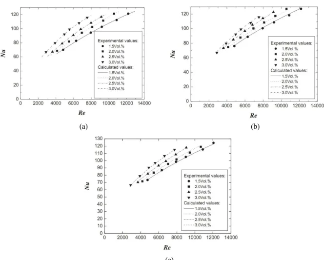
Li et al. (2011) concentrated on the heat transfer
performance of nanofluids in a submerged impinge-ment jet system. Their results demonstrated that nanofluids are promising new coolants compared to pure water. They modified Webb and Ma’s (1995) correlation for the nanofluids and proposed a Nusselt predicting correlation as follows:
0.8464 0.2715
0.5375 1/3
2 3
Nu 0.2464(1.0 2.2061 Pe )
Re Pr
1.0 0.3923(H / D) 0.0086(H / D) 0.0259(H / D)
= + φ
⎡ + + ⎤
×⎢⎣− ⎥⎦
(1)
where, Nu, φ, Pe, Re, H and D, are the Nusselt number, volume fraction of nanoparticles, Peclet number, Reynolds number, jet to target distance and diameter of nozzle, respectively. Also, good agreement between results obtained from their experimental study and the prediction model were shown (Figure 4).
(a) (b)
(c)
Figure 4: Comparison between the measured data and the calculated values from correlation (1): (a) H/D = 1;
In another study, the jet boiling heat transfer of a water-CuO particle suspension (nanofluids) jet impingement on a large flat surface was experimen-tally investigated by Liu and Qiu (2007). The experimental results were compared with those with water. The effects of the nanoparticle concentration and the flow conditions on the nucleate boiling heat transfer and the critical heat flux (CHF) were investigated. The experimental data showed that the jet boiling heat transfer for the water-CuO nanofluids is significantly different from that for water. The surface tension of the nanofluids was equal to about 75% of that of water, and it hardly changed with different concentrations. The nanofluids have poor nucleate boiling heat transfer compared with the base fluid due to formation of a very thin nanoparticle sorption layer on the heated surface. The reasons were that the solid-liquid contact angle decreased due to a very thin sorption layer on the heated surface and the jet and agitating effect of the nanoparticles in the sub-film layer enhances the supply of liquid to the surface. They concluded that the CHF of nanofluids increased gradually with the increasing particle concentration in the low concen-tration range, but was constant after the particle concentration exceeded 1 wt%. The CHF for nano-fluids increased about 25% compared with that of water. A sorption layer is formed on the heated surface during jet boiling of nanofluids. After the sorption layer is cleaned out by the water jet, there still exists a very thin coating layer on the surface. The surface roughness and the contact angle are decreased due to the formation of the sorption layer.
NUMERICAL STUDIES
Roy et al. (2004) performed a numerical study
of the heat transfer performance of a liquid im-pingement jet using -Al2O3 nanoparticles suspended
in water. They indicated a considerable improvement in heat transfer rates (up to 100% in local heat transfer coefficient) even at small particle volume fractions.
Most studies related to nanofluids used in impinge-ment jet heat transfer are limited to water- Al2O3
nanofluids. Almost all works, whether experimental or numerical, utilize a single circular nozzle. None-theless, other nanoparticle materials are promising such as carbon nanotubes and CuO. For example, Wang Xiangqi (2007) studied the utilization of this method to cool microelectronic components. He used four types of nanofluids and observed interesting results. For instance, in the case of oil-CNT nanofluids,
the results demonstrated a 100% enhancement in Nusselt number and, therefore, in heat transfer performance.
It should be noted that for electronic chip cooling by nanofluids impingement jets, the use of an array of jets is important and more interesting because of the desired uniform temperature distribution on electronic chip. However, no study using an array of jets involving nanofluids is available.
Another interesting numerical study performed by Palm et al. (2006) used well-known accurate models to predict temperature-dependent nanofluids proper-ties like the effective viscosity and thermal conduc-tivity. Their results demonstrated clearly that the temperature-dependent models gave a higher heat transfer enhancement and lower wall stress com-pared to the constant properties models.
Heat transfer enhancement and pumping power in an impingement jet using suspended nanoparticles (Al2O3 dispersed in water) was investigated by
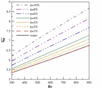
Gherasim et al. (2011). They demonstrated clearly a direct relation between nanoparticle volume fraction and Nusselt number enhancement. Results indicated that heat transfer enhancement is possible in this application using nanofluids. In general, it was noted that the mean Nusselt number increased with particle volume fraction and Reynolds number and decreased with an increase in disk spacing. On the other hand, the important increase in associated pumping power may impose some limitations on the efficient use of nanofluid in a radial impingement system. Their results are shown in Figures 5 and 6.
Figure 5: Influence of Reynolds number and particle
Figure 6: Pumping power required as a function of Reynolds number (Manca et al., 2011).
Manca et al. (2011) studied a confined slot jet with alumina-water nanofluids. The flow is turbulent and a constant temperature is applied on the imping-ing fluid. Also, a simping-ingle-phase model approach was adopted. Their local Nusselt number profiles showed the highest values at the stagnation point, and the lowest at the end of the heated plate. The highest values of the average Nusselt numbers increased as the particle concentration and Reynolds numbers increased, the highest values being observed for H/W = 10. A maximum increase of 18% was detected at a 6% volume fraction of nanoparticles.
An experimental investigation to study the heat transfer between a vertical round alumina-water nanofluids jet and a horizontal circular round surface was carried out by Zeitoun and Ali (2012). They found that the heating disk diameter shows reverse effect on heat transfer. It was also found that present-ing the data in terms of Reynolds number at the impingement jet diameter can take into account both the effects of jet heights and nozzle diameter. Showing the data in terms of Peclet numbers at fixed impinge-ment nozzle diameter makes the data less sensitive to the percentage change of the nanoparticle concentration. Finally, a general heat transfer correlation is obtained verses Peclet numbers using the nanoparticle concen-trations and the nozzle diameter ratio:
0.5 2
e e
i i
2.136 0.933 i
D D
Nu 0.2 5.022
D D
(1 m) Pe
− −
⎛ ⎛ ⎞ ⎛ ⎞ ⎞
⎜ ⎟
=⎜ ⎜ ⎟ − ⎜ ⎟ ⎟
⎝ ⎠ ⎝ ⎠
⎝ ⎠
−
(2)
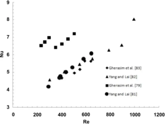
To better understand the behavior of liquid impingement jets with nanofluids, we provide two graphs; comparing the results of important studies in this area. It is clear that the heat transfer enhance-ment increases with any increase in nanoparticle volume fraction and Reynolds number (see Figures 7, 8).
Figure 7: Comparison of some important data for
Nusselt number as a function of nanoparticle volume fraction.
Figure 8: Comparison of some important data for
Nusselt number versus Reynolds number.
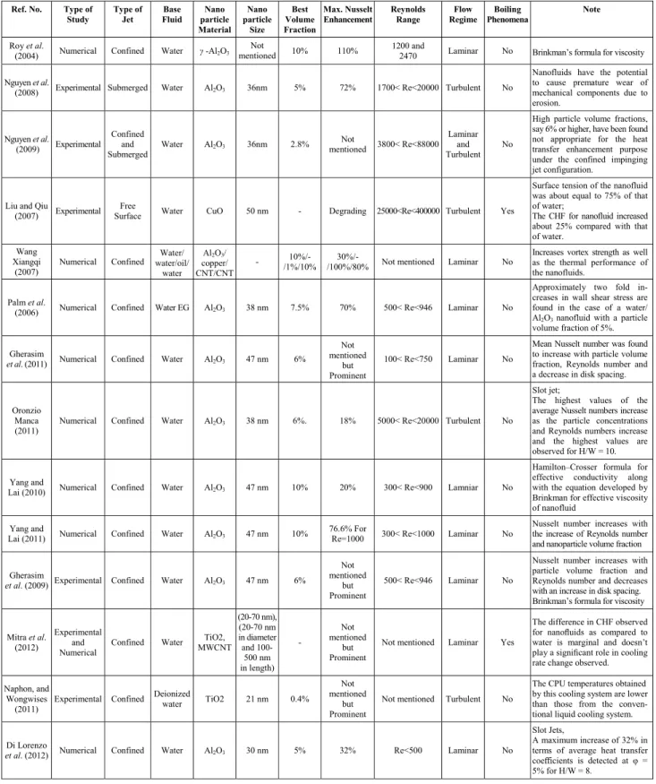
Table 2: Studies done using nanofluids in liquid impingement jet heat transfer
Ref. No. Type of Study
Type of Jet
Base Fluid
Nano particle Material
Nano particle
Size Best Volume Fraction
Max. Nusselt Enhancement
Reynolds Range
Flow Regime
Boiling Phenomena
Note
Roy et al.
(2004) Numerical Confined Water γ -Al2O3
Not
mentioned 10% 110% 1200 and
2470 Laminar No Brinkman’s formula for viscosity Nguyen et al.
(2008) Experimental Submerged Water Al2O3 36nm 5% 72% 1700< Re<20000 Turbulent No
Nanofluids have the potential to cause premature wear of mechanical components due to erosion.
Nguyen et al.
(2009) Experimental Confined
and Submerged
Water Al2O3 36nm 2.8%
Not
mentioned 3800< Re<88000 Laminar
and Turbulent
No
High particle volume fractions, say 6% or higher, have been found not appropriate for the heat transfer enhancement purpose under the confined impinging jet configuration.
Liu and Qiu
(2007) Experimental Free
Surface Water CuO 50 nm - Degrading 25000<Re<400000 Turbulent Yes
Surface tension of the nanofluid was about equal to 75% of that of water;
The CHF for nanofluid increased about 25% compared with that of water.
Wang Xiangqi
(2007)
Numerical Confined Water/ water/oil/
water Al2O3/
copper/ CNT/CNT
- 10%/-/1%/10%
30%/-/100%/80% Not mentioned Laminar No
Increases vortex strength as well as the thermal performance of the nanofluids.
Palm et al.
(2006) Numerical Confined Water EG Al2O3 38 nm 7.5% 70% 500< Re<946 Laminar No
Approximately two fold in-creases in wall shear stress are found in the case of a water/ Al2O3 nanofluid with a particle
volume fraction of 5%. Gherasim
et al. (2011) Numerical Confined Water Al2O3 47 nm 6%
Not mentioned
but Prominent
100< Re<750 Laminar No
Mean Nusselt number was found to increase with particle volume fraction, Reynolds number and a decrease in disk spacing. Oronzio
Manca (2011)
Numerical Confined Water Al2O3 38 nm 6%. 18% 5000< Re<20000 Turbulent No
Slot jet;
The highest values of the average Nusselt numbers increase as the particle concentrations and Reynolds numbers increase and the highest values are observed for H/W = 10. Yang and
Lai (2010) Numerical Confined Water Al2O3 47 nm 10% 20% 300< Re<900 Lamniar No
Hamilton–Crosser formula for effective conductivity along with the equation developed by Brinkman for effective viscosity of nanofluid
Yang and
Lai (2011) Numerical Confined Water Al2O3 47 nm 10%
76.6% For
Re=1000 300< Re<1000 Laminar No
Nusselt number increases with the increase of Reynolds number and nanoparticle volume fraction Gherasim
et al. (2009) Experimental Confined Water Al2O3 47 nm 6%
Not mentioned
but Prominent
500< Re<946 Laminar No
Nusselt number increases with particle volume fraction and Reynolds number and decreases with an increase in disk spacing. Brinkman’s formula for viscosity Mitra et al.
(2012)
Experimental and Numerical
Confined Water TiO2, MWCNT
(20-70 nm), (20-70 nm in diameter and
100-500 nm in length)
-
Not mentioned
but Prominent
Not mentioned Laminar Yes
The difference in CHF observed for nanofluids as compared to water is marginal and doesn’t play a significant role in cooling rate change observed. Naphon, and
Wongwises (2011)
Experimental Confined Deionized
water TiO2 21 nm 0.4% Not mentioned
but Prominent
Not mentioned Turbulent No
The CPU temperatures obtained by this cooling system are lower than those from the conven-tional liquid cooling system. Di Lorenzo
et al. (2012) Numerical Confined Water Al2O3 30 nm 5% 32% Re<500 Laminar No
Slot Jets,
A maximum increase of 32% in terms of average heat transfer coefficients is detected at φ = 5% for H/W = 8.
Continuation Table 2
Ref. No. Type of Study
Type of Jet
Base Fluid
Nano particle Material
Nano particle
Size Best Volume Fraction
Max. Nusselt Enhancement
Reynolds Range
Flow Regime
Boiling Phenomena
Note
Feng
(2010) Numerical Confined Water Al2O3 30 - 47 nm 4%
Not mentioned
but Prominent
Re<800 Laminar No
The results indicate that
nano-fluids are when compared to pure water. Specifically, smoother mixture flow fields and tem-perature distributions can be achieved.
Zeitoun and
Ali (2012) Experimental Free
Surface Water Al2O3 10 nm 10% 75% 2500<Re<24000 Turbulent No
General heat transfer correlation is obtained verses Peclet numbers using nanoparticle concentra-tions and the nozzle diameter ratio as parameters.
Li et al.
(2012) Experimental Submerged Water Cu
25, 100
nm 3% 52% 3000<Re<16000 Turbulent No
By considering the effects of the suspended nanoparticles as well as the condition of impinging jet, a new heat transfer correla-tion of nanofluids for the sub-merged single jet impingement has been proposed.
Roy et al.
(2004) Numerical Confined Water γ -Al2O3
Not
mentioned 10% 110% 1200 and
2470 Laminar No Brinkman’s formula for viscosity Nguyen et al.
(2008) Experimental Submerged Water Al2O3 36nm 5% 72% 1700< Re<20000 Turbulent No
Nanofluids have the potential to cause premature wear of mechanical components due to erosion.
Nguyen et al.
(2009) Experimental Confined
and Submerged
Water Al2O3 36nm 2.8% mentioned Not 3800< Re<88000
Laminar and Turbulent
No
High particle volume fractions, say 6% or higher, have been found not appropriate for the heat transfer enhancement purpose under the confined impinging jet configuration.
Li et al.
(2011) Experimental Submerged Water Cu 25 - 100 nm 3% 52% 2000<Re<16000 Turbulent No
A new heat transfer correlation of nanofluids for the submerged single jet impingement has been proposed.
Liu and Qiu
(2007) Experimental Free
Surface Water CuO 50 nm - Degrading 25000<Re<400000 Turbulent Yes
Surface tension of the nanofluid was about equal to 75% of that of water;
The CHF for nanofluid increased about 25% compared with that of water.
Wang Xiangqi
(2007)
Numerical Confined Water/ water/oil/
water Al2O3/
copper/ CNT/CNT
- 10%/-/1%/10%
30%/-/100%/80% Not mentioned Laminar No
Increases vortex strength as well as the thermal performance of the nanofluids.
Palm et al.
(2006) Numerical Confined Water
EG Al2O3 38 nm 7.5% 70% 500< Re<946 Laminar No
Approximately two fold in-creases in wall shear stress are found in the case of a water/ Al2O3 nanofluid with a particle
volume fraction of 5%. Gherasim
et al. (2011) Numerical Confined Water Al2O3 47 nm 6%
Not mentioned
but Prominent
100< Re<750 Laminar No
Mean Nusselt number was found to increase with particle volume fraction, Reynolds number and a decrease in disk spacing. Oronzio
Manca (2011)
Numerical Confined Water Al2O3 38 nm 6%. 18% 5000< Re<20000 Turbulent No
Slot jet;
The highest values of the aver-age Nusselt numbers increase as the particle concentrations and Reynolds numbers increase and the highest values are observed for H/W = 10.
Yang and
Lai (2010) Numerical Confined Water Al2O3 47 nm 10% 20% 300< Re<900 Lamniar No
Hamilton–Crosser formula for effective conductivity along with the equation developed by Brinkman for effective viscosity of nanofluid
Yang and
Lai (2011) Numerical Confined Water Al2O3 47 nm 10% 76.6% for Re=1000 300< Re<1000 Laminar No
Nusselt number increases with the increase of Reynolds number and nanoparticle volume fraction
Continuation Table 2
Ref. No. Type of Study
Type of Jet
Base Fluid
Nano particle Material
Nano particle
Size Best Volume Fraction
Max. Nusselt Enhancement
Reynolds Range
Flow Regime
Boiling Phenomena
Note
Gherasim
et al. (2009) Experimental Confined Water Al2O3 47 nm 6%
Not mentioned
but Prominent
500< Re<946 Laminar No
Nusselt number increases with particle volume fraction and Reynolds number and decreases with an increase in disk spacing; Brinkman’s formula for viscosity Mitra et al.
(2012)
Experimental and Numerical
Confined Water TiO2, MWCNT
(20-70 nm), (20-70 nm in diameter and
100-500 nm in length)
-
Not mentioned
but Prominent
Not mentioned Laminar Yes
The difference in CHF observed for nanofluids as compared to water is marginal and doesn’t play a significant role in cooling rate change observed. Naphon, and
Wongwises (2011)
Experimental Confined Deionized
water TiO2 21 nm 0.4% Not mentioned
but Prominent
Not mentioned Turbulent No
The CPU temperatures obtained by this cooling system are lower than those from the conven-tional liquid cooling system. Di Lorenzo
et al. (2012) Numerical Confined Water Al2O3 30 nm 5% 32% Re<500 Laminar No
Slot Jets,
A maximum increase of 32% in terms of average heat transfer coefficients is detected at φ = 5% for H/W = 8.
Feng
(2010) Numerical Confined Water Al2O3 30 - 47 nm 4%
Not mentioned
but Prominent
Re<800 Laminar No
The results indicate that
nano-fluids are when compared to pure water. Specifically, smoother mixture flow fields and tem-perature distributions can be achieved.
CONCLUSION
In this study, we concentrated on a liquid im-pingement jet and its combination with nanofluids. Thorough reviewing important studies, we concluded that,
The Nusselt number grows as the Reynolds
number increases, whether in the cases involving nanofluids or pure fluids.
The Nusselt number enhances with the particle volume fraction and decreases with an increase in the nozzle to target distance.
The increase in pressure drop is significant with the presence of nanoparticles.
The parameters that affected the Nusselt number in liquid impingement jets are fluid properties, the geometry of jets, jet velocity, Reynolds number, Prandtl number, nozzle to target distance, material properties of the target, porosity of the target, jet subcooling for boiling phenomena and nozzle diameter. It seems that there is a need for more study of physical properties and the porosity of target and jet to jet interaction before and after impinging. Different arrays of multiple jets should also be investigated for an acceptable optimization between desirability of more jets and the problem of enhancing pressure drop. The few studies on impingement jets with nanofluids that have been performed and their interesting aspects are shown. However, for the
acceptance of these promising characteristics the heat transfer community needs more evidences. More studies are required to develop models for Nusselt number prediction using nanofluids. Also, there is no study of an array of liquid impingement jets using nanofluids and such a study should be performed in the near future to determine the effects of nanoparticles on the heat transfer performance of multiple jets systems.
NOMENCLATURE
corr
A Area corresponding to a
single jet
2 m
r
A Ratio of impingement region
area to target area, 2 2 e (1.9d) / D
B Slot jet nozzle width m
i
d ,D Diameter of nozzle m
e
D Effective target diameter (4A / )h π1/2 (mm)
i
D Jet diameter at impingement m
n
d Jet diameter m
Ek Ekman number,
( )
2f d
Ek= ν / 4 rΩ
1
Ek Ekman number,
(
2)
1 f 1 d
2
Ek Ekman number,
(
2)
2 f 2 d
Ek = ν / 4Ω r
* c
Gr Modified Grashof number at the center of the heater
H ,L/D Jet-to-target distance m
k Thermal conductivity W / m.K
n Number of jets.
L Half of the heat source length, average length of the wall jet region
m
e
L Length of the nozzle unit cell for an array
m
D /
L Nozzle-to-surface
distance
m
l Length of the side of the square heat source, orifice thickness
m
m Nanofluid particle mass
concentration
Nu Nusselt number
o
Nu Nusselt number at the stagnation point
s , c
Nu Nusselt number at the center of the heater Pr Prandtl number
Pe Peclet number
Pe Peclet number at
impingement
R Equivalent radius of the target
m
Re Reynolds number
r Radial distance from the stagnation point
m
d p/r
r Confinement plate to disk
radius ratio (confinement ratio)
S Nozzle pitch (distance between neighboring nozzles in a square array)
) m (
NP
S Nozzle-to-surface distance. m
s Jet-to-jet spacing m
T Temperature °C or K
s
T Surface temperature °C or K
W Nozzle width m
Y ,
X Non-dimensional Cartesian
coordinates, X=x / L, Y=y / L
z Nozzle exit to impingement
plate spacing
m
ph Perimeter of micro-channel,
2(Wch + Hch)
m
Greek Symbols
ε Thermal conductivity ratio,
s f
k / k
ε = ,
2
J ( d ) / (4Acorr)
α = π
f
θ Non-dimensional fluid
temperature,
f (Tf T ) / (Tc h T )c
θ = − −
s
θ Non-dimensional solid
temperature,
s (Ts T ) / (Tc h T )c
θ = − −
φ Volume fraction of
nanoparticles
θ Jet angle. degree
Dimensionless nozzle–to– plate spacing, Hn/dn
Subscript
n nozzle
s boundary layer solution, solid phase
t total (fluid + solid)
c cold wall
h hot wall
f fluid phase
i inlet
o outlet
REFERENCES
Aihara, T. and Kim, J. K., Boiling heat transfer of a microimpinging jet of liquid nitrogen in a very slender cryoprobe. International Journal of Heat and Mass Transfer, vol. 1, no. 36, pp. 169-175 (1993).
Amano, R. S. and Brandt, H., Numerical study of turbulent axisymmetric jets impinging on a plate and flowing into an axisymmetric cavity. Journal of Fluid Engineering, vol. 106, pp. 410-417 (1984).
Ashforth-Frost, S. and Rudel, U. W., Thermal and hydrodynamic visualisation of a water jet im-pinging on a flat surface using microencapsulated liquid crystals. International Journal of Fluid Dynamics, vol. 7, pp. 1-7 (2002).