Film Fraction in a Vertical Circular Venturi Scrubber
J. of the Braz. Soc. of Mech. Sci. & Eng. Copyright 2011 by ABCM Special Issue 2011, Vol. XXXIII / 233
Andressa Pinheiro Guerra
[email protected] Federal University of São Carlos Department of Chemical Engineering 13565-905 São Carlos, SP, Brazil
Vádila Giovana Guerra
[email protected] Federal University of São Carlos Department of Chemical Engineering 13565-905 São Carlos, SP, BrazilJosé Renato Coury
[email protected] Federal University of São Carlos Department of Chemical Engineering 13565-905 São Carlos, SP, BrazilJosé Antônio S. Gonçalves
[email protected] Federal University of São Carlos Department of Chemical Engineering 13565-905 São Carlos, SP, BrazilFilm Fraction in a Vertical Circular
Venturi Scrubber
The liquid film affects significantly the Venturi scrubber efficiency. Film fraction was measured in a vertically mounted laboratory scale Venturi scrubber with a 0.020 m throat diameter. The liquid was injected at the throat by one to six 0.001 m holes. The throat gas velocity varied from 50 to 90 m/s and the relative jet penetration varied between 0.05 and 0.85. A special test section with a slot was used to extract the film. The test section could be placed at different axial positions, allowing measurements at 0.0075, 0.0275 and 0.0675 m after the injection point. Results showed that film fraction varies as a function of the relative jet penetration and with distance from the injection point. There exists an optimal relative jet penetration (between 0.25 and 0.40) which minimizes film fraction. Film fraction increased with axial distance in the range studied, up to 3.375 throat diameters after the injection point.
Keywords: film fraction, Venturi scrubber, jet penetration
Introduction
Air pollution can cause human health problems ranging from small allergies to severe respiratory diseases. Particulate matter below 5 µm in size are the most dangerous, as they can penetrate inside the lungs. This motivates government and industries to work together to find solutions to mitigate emissions of particulate matter to the atmosphere.
A Venturi scrubber, shown schematically in Fig. 1, is a highly efficient device capable of removing dust from industrial gaseous emissions. In a Venturi scrubber, the aerosol reaches high velocities in the throat of a Venturi type tube. Liquid is most commonly introduced as jets by orifices in the throat. The jets are atomized by the high velocity gas. The droplets are responsible for the collection of the particulate matter. A fraction of the injected liquid, however, deposit on the equipment walls, where it flows as a liquid film. This film contributes little to the scrubber’s particulate matter collection efficiency, as the surface area per unit volume of the liquid film is much smaller than that of the liquid droplets. Film fraction is defined as the fraction of the total injected liquid which flow as film attached to the equipment walls.
Figure 1. Scheme of a typical Venturi scrubber with liquid injected as jets.
The maximum jet centerline penetration (lmax) was defined by
Viswanathan et al. (1983) as the transversal distance travelled by the jet until it becomes parallel to the gas main flux. This distance can be made dimensionless if divided by the distance between the wall which contains the jet injection orifice and its opposing wall. Viswanathan et al. (1983) correlated the jet penetration thus defined with the operational conditions of their experiments:
) 2 ( 10
458 . 1 ) 2
( 0 0 0
4
0 max
R N D
A G L x
R
l th
g l
(1)
Gonçalves et al. (2004) and Daher (2008) have shown that the jet penetration defined by Eq. (1) is one of the most important parameters affecting film fraction in Venturi scrubbers. Both small and excessive jet penetrations (Fig. 2) produce droplets near the equipment walls, making droplet deposition easier and, therefore, leading to high film fraction. Those authors presented evidence that there is an optimum jet penetration which minimizes film fraction. Daher (2008), however, studied only rectangular cross sections Venturi scrubbers mounted horizontally. In that setup, the author found that the influence of gravity could not be disregarded in the film formation and, therefore, suggested further studies with a vertically mounted scrubber. Viswanathan et al. (1997) also found that the jet penetration (in the form of the L/G parameter) was important to describe film fraction. However, as they have not worked with excessive jet penetration, the authors found a continuous decrease of film fraction with the increase of jet penetration.
Guerra et al.
234 / Vol. XXXIII, Special Issue 2011 ABCM
(a)
(b)
Figure 2. Photographical images of transversal jets in a Venturi scrubber. (a) Vg = 64 m/s and Vj = 5.3 m/s; (b) Vg = 64 m/s and Vj = 14.8 m/s.
The variation of film fraction with axial distance from the injection point was measured by Viswanathan et al. (1985, 1997), in a Venturi with a rectangular cross section and liquid injected as jets, and by Azzopardi (1993), in a circular Venturi with liquid injected as a film upstream the convergence (this injection arrangement is
called “wetted approach”). These authors used a porous wall to
remove the film (by an applied pressure difference). As the porous wall needed to be several centimeters long in order to be able to remove all the film, it was impossible to measure the film fraction near the injection point (in the case of Wiswanathan et al., 1985) or near the beginning of the throat (in the case of Azzopardi, 1993). Both these studies found that the variation of film fraction with axial distance was not very significant. Gonçalves et al. (2004), however, using a slot technique which allows film removal much closer to the injection point, found that the film fraction increases rapidly with axial distance from the injection point up to three throat diameters, remaining approximately constant thereafter.
The purpose of this study is to present film fraction data on a vertically mounted laboratory scale Venturi scrubber with a circular cross section as a function of the throat gas velocity, liquid-to-gas ratio, jet penetration and axial distance along the scrubber.
Nomenclature
Ath = throat area, m 2
D0 = injection orifice diameter, m
lmax = maximum penetration of the jet’s centerline, m
L/G = ratio of volumetric liquid to gas flow rates, l/m3 N0 = number of liquid injection orifice, dimensionless
Vg = gas velocity, m/s
2R0 = distance between the wall containing the injection
orifice and the opposite wall, m
Z = axial distance between film fraction measurement point and injection point, m
Greek Symbols
ρg = gas density, kg/m3
ρl = liquid density, kg/m3
Experimental Details
Film fraction measurements were made in a Venturi scrubber with circular cross section which was mounted vertically. The geometrical details about the scrubber are presented in Table 1. The fluids used were air and water. Injection occurred through one to six 0.001 m orifices located at the beginning of the throat. By varying the gas and liquid flow-rates, it was possible to achieve dimensionless jet penetrations (as defined by Viswanathan et al. (1983) from 0.05 to 0.85. Gas velocity in the throat was 50, 70 and 90 m/s. The axial distances used for film fraction measurements were 0.0075, 0.0275 and 0.0675 m after the injection point.
Film fraction was measured using the slot method. This methodology was used successfully by Gonçalves et al. (2004) and was inspired in the work of Hay et al. (1996). This method is presented schematically in Fig. 3. The film is directed towards a slot and a small reservoir, removed from the device by an applied pressure difference, and collected in a recipient. In these experiments, the pressure inside the throat was approximately 8% higher than the outside atmospheric pressure, which was enough to push the liquid out of the device.
Table 1. Dimensions of the Venturi scrubber used in this study.
Quantity Value
Inlet and outlet diameter 0.035 m
Throat diameter 0.020 m
Convergence length 0.011 m
Divergence length 0.086 m
Convergence half angle 34,0º
Divergence half angle 5,0º
In order to control the flow coming out of the test section through the slot and allow the removal of all the liquid with a minimum of air, adjustable flow restrainers were used.
Film Fraction in a Vertical Circular Venturi Scrubber
J. of the Braz. Soc. of Mech. Sci. & Eng. Copyright 2011 by ABCM Special Issue 2011, Vol. XXXIII / 235
Results and Discussion
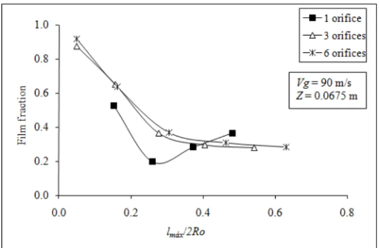
Jet penetration is an important parameter affecting liquid distribution in a Venturi scrubber, including film fraction. Depending on the penetration, the droplets resulting from the jet atomization can be created near or far from the walls. The influence of jet penetration on film fraction can be seen in Figs. 4 and 5, which present film fraction as a function of the dimensionless jet penetration (lmax/2R0).
Figure 4. Film fraction as a function of lmax/2R0. Vg = 50 m/s; Z = 0.0675 m.
It can be observed in Fig. 4 that, regardless of the number of injection orifices utilized, film fraction presents the same behavior with a change in jet penetration. The curves exhibit a minimum between the penetrations of 0.25 and 0.4. When the jet penetration increases from 0 to 0.25, film fraction decreases. With increasing penetration, the jet moves away from the wall that contains the injection orifices, which means that the droplets are formed nearer to the center of the duct and away from the walls. After the point of minimum, film fraction starts to increase with increasing jet penetration. In this case the penetration is excessive, and the droplets are formed nearer the walls opposite to the injection orifice. Moreover, the droplets just formed inherit the momentum from the jet, and tend to move in the direction of the opposite walls.
The number of injection orifices also influenced the film fraction, as it can be seen in Fig. 4. For a same jet penetration (according to Viswanathan et al. (1983) definition, see Eq. (1)), a higher number of injection orifices mean that there is more liquid in the throat of the Venturi. This means that the liquid holdup is greater. The gas needs to increase its velocity to adjust to the increased liquid holdup. By doing so, the jet is actually more flattened than it would be if the liquid holdup was smaller. For smaller jet penetrations, this increased flattening places the jet even closer to the walls, meaning a higher film fraction for the same jet penetration. For excessive jet penetrations, the flattening places the jet closer to the center, and a lower film fraction can be expected. This is exactly what is observed in Fig. 4, and it suggests the need for a correction in Eq. (1).
A comparison between Figs. 4 and 5, which differ on account of the nominal throat gas velocity, reveals that, for small penetrations (between 0 and 0.2), film fraction is smaller for the higher gas velocity, while for intermediate jet penetrations (between 0.2 and 0.5), film fraction is higher for the higher gas velocity. The higher gas velocity is able to produce smaller droplets (Guerra et al., 2009). These droplets spread better than the larger droplets due to turbulence diffusion. When the droplets formed near the wall are smaller, a larger fraction of them tend to diffuse away from the
walls. On the other hand, when the droplets formed near the center are smaller, a larger fraction of them tend to reach the walls.
Figure 5. Film fraction as a function of lmax/2R0. Vg = 90 m/s; Z = 0.0675 m.
Figure 6, with data for the injection through three orifices, exhibits a similar behavior. For both the smaller and higher jet penetrations, film fraction decreased with increasing gas velocity. For the intermediate jet penetration, film fraction increased with increasing gas velocity.
0.0 0.2 0.4 0.6 0.8 1.0
0 20 40 60 80 100
Vg (m/s)
F
il
m
f
ra
ct
ion t
lmax/2Ro=0.16 lmax/2Ro=0.28 lmax/2Ro=0.54
Figure 6. Film fraction as a function of gas velocity for different jet
penetrations. Injection through three orifices. Z = 0.0675 m.
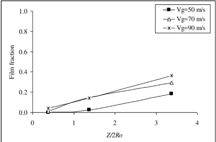
The variation of film fraction with distance from injection point is presented in Figs. 7, 8 and 9. Near the injection point (0.007.5 m downstream) film fraction is lower, as expected, because the liquid is injected in a jet going towards the center of the duct. Film fraction then increases with increasing distance from the injection point, indicating that, in the range of distances studied (0.0075, 0.0275 and 0.0675 m after injection), droplet deposition still dominates over entrainment.
Guerra et al.
236 / Vol. XXXIII, Special Issue 2011 ABCM
0.0 0.2 0.4 0.6 0.8 1.0
0 1 2 3 4
Z/2Ro
F
il
m
f
ra
ct
ion t
Vg=50 m/s Vg=70 m/s Vg=90 m/s
Figure 7. Film fraction as a function of the dimensionless axial distance
from injection point Z/2R0. Dimensionless jet penetration of 0.28 and
injection through three orifices.
0.0 0.2 0.4 0.6 0.8 1.0
0 1 2 3 4
Z/2Ro
F
il
m
f
ra
ct
ion t
Vg=50 m/s Vg=70 m/s Vg=90 m/s
Figure 8. Film fraction as a function of the dimensionless axial distance
from injection point Z/2R0. Dimensionless jet penetration of 0.53 and
injection through three orifices.
0.0 0.2 0.4 0.6 0.8 1.0
0 1 2 3 4
Z/2Ro
F
il
m
f
ra
ct
ion t
Vg=50 m/s Vg=70 m/s
Figure 9. Film fraction as a function of the dimensionless axial distance
from injection point Z/2R0. Dimensionless jet penetration of 0.72 and
injection through three orifices.
A penetration close to the intermediate/excessive border is presented in Fig. 8. Film fraction is still low (expect for the point where it is over 0.6), but the effect of the jet being thrown towards
the opposite wall begins to be felt. When the droplets are formed, they tend to inherit the momentum of the jet, which exhibits a velocity in the direction of the opposite wall. The high velocity of the gas drags the droplets in such a way that their trajectory tends to align with the main gas flow, overshadowing their initial momentum in a different direction. However, if the jet penetrates high enough that the droplets are already formed near the opposite walls, there may be not enough time for them to bend their trajectories and align with the main flow before they hit the opposite wall. This is particularly felt for low gas velocities, as the drag is lower, as can be clearly seen in Fig. 8, where, for a gas velocity of 50 m/s and after 0.0675 m from injection, most of the droplets had deposited on the (opposite) walls. The same trend is present in Fig. 9, which represents a case of excessive jet penetration. In this case, overall film fractions are even higher.
Conclusions
From the results of this study it can be concluded that:
• Film fraction is strongly dependent on jet penetration. It is higher for both small and excessive jet penetrations, and reaches a minimum for intermediate jet penetrations.
• Film fraction is dependent on gas velocity, but it is not a straightforward relationship and depends on jet penetration and on the axial measurement position.
• Film fraction depends on the axial position. For injection in the form of jets and the dimensionless axial positions studied in this work (0.375, 1.375 and 3.375), film fraction increases steadily with axial distance.
• For an equal jet penetration, the increase in the number of jets (injection orifices) increases the liquid holdup, thereby decreasing the gas holdup, modifying the behavior of the jets and the film fraction in a similar way as if a higher superficial gas velocity were being used.
Acknowledgements
The authors are grateful to CNPq for the financial aid that made this study possible.
References
Azzopardi, B.J., 1993, “Liquid distribution in Venturi scrubbers: the
importance of liquid films on the channel walls”, Chemical Engineering Science, Vol. 48, No. 15, pp. 2807-2813.
Daher, M.A.F., 2008, “Fração de filme líquido nas paredes de um lavador Venturi”, (in Portuguese), Master Dissertation, Federal University of São Carlos, São Carlos, SP, Brazil.
Gonçalves, J.A.S., Costa, M.A.M., Falaguasta, M.C.R., Coury, J.R.,
2004, “Film Fraction in Pease-Anthony Venturi Scrubbers”, 16th Proceedings of the 16th CHISA (CD-ROM), Vol. 1, Prague.
Guerra, V.G., Gonçalves, J.A.S., Coury, J.R., 2009, “Experimental investigation on the effect of liquid injection by multiple orifces in the
formation of droplets in a Venturi scrubber”, Journal of Hazardous Materials, Vol. 161, pp. 351-359.
Hay, K.J., Zi-Chao Liu, Hanratty, T.J., 1996, “Relation of deposition to
drop size when the rate is nonlinear”, Int. J. Multiphase Flow, Vol. 22, No. 5, pp. 829-848.
Viswanathan, S., Gnyp, A.W., Pierre, C.C., 1983, “Jet penetration measurements in a Venturi scrubbers”, Canadian Journal of Chemical Engineering, Vol. 61, pp. 504-508.
Viswanathan, S., Gnyp, A.W., Pierre, C.C., 1985, “Annular flow pressure drop model for Pease-Anthony-Type Venturi scrubbers”, AIChE Journal., Vol. 31, pp. 1947-1959.
Viswanathan, S., Gnyp, A.W., ST. Pierre, C.C., 1997, “Estimating film