Impact of Jet Reynolds Number and Feed
Channel Geometry on Heat Transfer in a
Channel with Inclined Target Surface Cooled by
Single Array of Centered Impinging Jets with
Outflow in Both Directions
Ali A. Al-Mubarak*, S. M. Shaahid** and Luai M. Al-Hadhrami ***
Abstract— An experimental investigation has been carried out to study the heat transfer characteristics in a channel with heated target plate inclined at an angle cooled by single array of equally spaced centered impinging jets for three different jet Reynolds numbers (Re=9300, 14400 and 18800). Air ejected from an array of orifices impinges on the heated target surface The target plate forms the leading edge of a gas turbine blade cooled by jet impingement technique. The work includes the effect of jet Re and feed channel aspect ratios (H/d = 5, 7, 9 where H=2.5, 3.5, 4.5 cm and d=0.5 cm) on the heat transfer characteristics for a given orifice jet plate configuration with outflow exiting in both directions (with inclined heated target surface). In general, It has been observed that, H/d=9 gives the maximum heat transfer over the entire length of the target surface as compared to all feed channel aspect ratios. H/d=9 gives 3% more heat transfer from the target surface as compared to H/d=5 (for Re=14400). Also, it has been observed that the magnitude of the averaged local Nusselt number increases with an increase in the jet Re for all the feed channel aspect ratios studied.
I. INTRODUCTION
Impingement heat transfer with high velocity gas jets has become an established method of convectively cooling surfaces in a wide variety of process and thermal applications. Examples include cooling of gas turbine airfoils and electronic equipment. In modern gas turbine design, the trend is toward high inlet gas temperature (1600–1800 ºK) for improving thermal efficiency and power density. Since these temperatures are far above the allowable metal temperature, the gas turbine blades must be cooled in order to operate without failure. Broad range of parameters affect the heat transfer distribution, like impinging jet Re, jet size, target surface geometry, spacing of the target surface from the jet orifices, orifice-jet plate configuration, outflow orientation, etc. Literature indicates that some of these parameters have been studied in appreciable depth [1-17].
Manuscript received February 28, 2011; revised April 07, 2011. (Reviewed March 22, 201). Center for Engineering Research, Research Institute, King Fahd University of Petroleum and Minerals, Dhahran 31261, Saudi Arabia.
* Graduate Student; e-mail: [email protected] ** Research Engineer; e-mail: [email protected] *** Associate Professor; e-mail: [email protected]
Chupp et al. [1] studied the heat transfer characteristics for the jet impingement cooling of the leading edge region of a gas turbine blade. Flourscheutz et al. [2] investigated the heat transfer characteristics of jet array impingement with the effect of initial crossflow. Metzger and Bunker [3] and Flourscheutz et al [4] used the liquid crystal technique to study the local heat transfer coefficients. The authors observed that the jet Nusselt number depends on the jet Re. Rasipuram and Nasr [5] studied air jet issuing out of defroster's nozzles and impinging on inclined windshield of a vehicle. Beitelmal et al [6] investigated the effect of inclination of an impinging air jet on heat transfer characteristics. Roy and Patel [7] studied the effect of jet angle impingement on local Nu and nozzle to target plane spacing at different Re. Ekkad et al [8] studied the effect of impinging jet angle ±45 on target surface by using transient liquid crystal technique for single Re = 1.28×10⁴. Tawfek [9] investigated the
effect of jet inclination on the local heat transfer under an obliquely impinging round air jet striking on circular cylinder. Yang and Shyu [10] presented numerical predictions of heat transfer characteristics of multiple impinging slot jets with an inclined confinement surface for different angles of inclination and Re. Yan and Saniei [11] dealt with measurement of heat transfer coefficient of an impinging circular air jet to a flat plate for different oblique angles (45-90°) and different Re (10000 & 23000). Ramiraz et al [12] investigated the convective heat transfer of an inclined rectangular plate with blunt edge at various Re (5600-38500) and angle of inclination (60-70°). Hwang and Cheng [13-15] performed an experimental study to measure local heat transfer coefficients in leading edge. Three right triangular ducts of the same altitude and different apex angles (30º, 45º & 60º) were tested for various jet Re (3000 ≤Re≤12000) and different jet spacing (s/d=3 and 6). Results show that an increase in Re increases the Nu.
and diameter of jet d=0.5 cm) on the heat transfer characteristics for a given orifice jet plate configuration with equally spaced centered holes with outflow exiting in both directions (with inclined heated target surface). The motivation behind this work is that the channel of turbine blade internal cooling circuit at the leading edge is inclined.
II. DESCRIPTION OF THE EXPERIMENT The schematic of the experimental set-up is depicted in Figure 1. Figure 2.1 shows the three-dimensional sketch of the test section. It consists of two channels joined by the orifice plate, which has a single array of equally spaced centered jets shown in Figure 3. The jet orifice plate thickness is twice the jet diameter. There are 13 jets on the orifice plate. The jet-to-jet spacing is 8 times the jet diameter and the orifice jet diameterd0.5cm. The length of the test section is 106.5 cm (Fig 2.1). The width of the feed channel (H) was varied from 2.5 to 4.5 cm (i.e. H/d=5, 7, 9, d=0.5 cm). The impingement target surface constitutes a series of 13 copper plates, each with 4.2
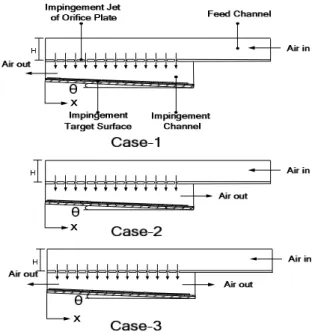
4.1 cm in size, arranged in accordance with the orifice jets such that the impingement jet hits the geometric center of the corresponding plate (however, first and last copper plates are slightly different in sizes). All the copper plates are separated from each other by 1 mm distance to avoid the lateral heat conduction, thus dividing the target surface into segments. The thickness of the copper plate is 0.5 cm. As shown in Figure 2.2, the length of impingement surface L is 57.3 cm (the target surface is inclined at angle 1.5º, the width of parallel flow side “S2” is 2 cm and the width of the opposite flow side “S1” is 3.5 cm).Figure 4 shows the schematic of the three different outflow orientations. The upper channel is called as the feed channel and the lower channel in which the jets impinge on the target surface is called as the impingement channel. The exit of jets in three different outflow orientations from the impingement channel creates different crossflow effects. In the present study, attention is focused on Case – 3. Figure 5 shows the details of the construction of the target surface.
III. PROCEDURE
Tests were carried out using a given orifice-jet plate (equally spaced centered holes) with jet diameter d0.5cm for a given jet Re = 9300 (for a given H/d ratio, for outflow passing in both directions) and for a constant heat flux power input. The heated target plate was oriented at a pre-defined angle (1.5º). The mass flow rate was adjusted to the required value for the experiment to be conducted and the air was blown continuously into the test section. Heat was supplied to the copper plates with electric resistive constant flux heaters from backside to provide uniform heat flux. The temperature of the copper plates was measured by two thermocouples mounted in a groove of 2.5 mm on the back of the copper plates. Thus the temperature of a particular plate has been taken as the average of the reading of two thermocouples. The temperature of the copper plates, pressure, temperature of the air at the inlet, and the mass flow rate were continuously monitored. After the temperature of the
copper plates reached the steady state condition, all the data was collected with Lab VIEW program. The Nu was then calculated based upon the collected data. The same procedure was repeated for different jet Re numbers (Re=14400 and 18800) and for different aspect ratios (H/d = 5, 7, 9) for a given orifice jet plate configuration with equally spaced centered holes with outflow exiting in both directions (with inclined heated target surface).
IV. DATA REDUCTION AND UNCERTAINTY ANALYSIS
The collected data was subjected to uncertainty analysis. The method for performing the uncertainty analysis has been taken from Taylor B.N. [16].
A. Jet Reynolds Number Calculations
The average velocity used to calculate the jet Reynolds number is calculated using the following equation
2 . avg
d 4 π 13
V V
(1)
The data reduction equation for the jet Re is taken as:
2 . avg
d 4 π 13
V μ
d ρ μ
d V ρ Re
(2)
B. Uncertainty in Jet Reynolds Number
The jet Reynolds number is a function of orifice jet diameter and volume flow rate and can be expressed mathematically as :
d) , V f(
Re . (3) The uncertainty in Re has been found to be about 2.2 %.
C. Nusslet Number Calculation
The total power input to all the copper plates was computed using the voltage and current, the former being measured across the heater, using the following equation:
VI R V
Qtotal 2 (4)
The heat flux supplied to each copper plate was calculated using:
total total "
A Q
q (5)
The heater gives the constant heat flux for each copper plate. The heat supplied to each copper plate from the heater is calculated using the following procedure:
i cp, " i
cp, q A
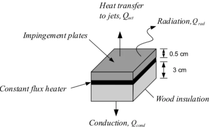
Where, i is the index number for each copper plate. The heat lost by conduction through the wood and to the surrounding by radiation is depicted in Figure 5 and has been estimated using the following equations for each plate.
t ) T (T A k
Q s,i w
i cp, wood i cond, (7)
)
T
(T
A
σ
ε
Q
4 surr 4 i s, i cp, irad,
(8)The actual heat supplied to each copper plate has been determined by deducting the losses from the total heat supplied to the heater.
)
Q
(Q
Q
Q
actual,i
cp,i
cond,i
rad,i (9) The local convective heat transfer coefficient for each of the copper plate has been calculated using:)
T
(T
A
Q
h
in i s, i cp, i actual,i
(10)The average temperature of the heated target surface Ts,i has been
taken as the average of the readings of the two thermocouples fixed in each copper plate. To calculate h, Tin has been
considered instead of the bulk temperature or the reference temperature. For a given case (for a given Re, H/d, and orifice-jet plate) Tin is fixed. It is measured at the test section inlet, where
the air first enters the feed channel. The non-dimensional heat transfer coefficient on the impingement target surface is represented by Nusselt number as follows:
air i i
h
k
d
Nu
(11)The hydraulic diameter has been taken as the diameter of the orifice jet. The data reduction equation for the Nusselt number is considered along with the heat losses by conduction and radiation. ) T (T ) T εσ(T ) T (T t k A RV k d Nu in i s, 4 Surr 4 i s, w i s, w total 2 air i (12)
D. Uncertainty in Nusselt Number
The uncertainty in the Nusselt number has been calculated using the Engineering equation Solver (EES) software. The uncertainty in Nu in the present study has been found to vary between ± 6% depending upon the jet velocity.
IV. RESULTS AND DISCUSSIONS Jet impingement heat transfer is dependent on several flow and geometrical parameters. The jet impingement Nusselt number is presented in a functional form as follows:
n
orientatio
outflow
,
d
H
,
d
X
Re,
f
k
d
h
Nu
air i i (13)Where, Re is the flow parameter, jet spacing to the diameter ratio (X/d) is the geometric parameter. The flow exit direction and target surface geometry are also important parameters having a considerable impact on impingement heat transfer.
The X location starts from the supply end of the channel as shown in Fig. 2. For the case-1 shown in Figure 4a, flow enters at X/d = 109.3 and exits at X/d = 0. For case-2 (Figure 4b), flow exits at X/d=109.3. For case-3 (Figure 4c), flow exits at both ends (X/d=0 and X/d=109.3). The flow is fully developed before entering the orifice jets. However, in the present study attention is focused on Case-3 (outflow in both directions).
A. Effect of Jet Re and Feed Channel Aspect Ratio on Local Nusselt Number
Figures 6-8 show the local Nusselt number distribution for three Reynolds numbers (Re=9300, 14400 and 18800) and for three H/d ratios (H/d = 5, 7, 9 where H=2.5, 3.5, 4.5 cm and d=0.5 cm) as a function of non-dimensional location X/d on the heated target surface (for outflow passing in both directions as shown in Figure 4c, and for a given orifice-jet plate with centered holes. In general, it has been observed it has been observed that the H/d profiles overlap each other at some points on the target plate (this is due to inter mixing of jets).
Figure 6 shows the effect of feed channel aspect ratio (H/d) on local Nusselt number for Re=9300 for orifice jet plate with centered holes with outflow passing in both directions. It can be observed that, H/d=9 gives the maximum heat transfer over the entire length of the target surface as compared to all feed channel aspect ratio studied. H/d=9 gives 2% more heat transfer from the target surface as compared to H/d=5. Whereas H/d=5 gives a maximum of 2% increase in heat transfer as compared to H/d=7. The crossflow boundary layer and jet strength almost equal over the entire target surface so the heat transfer is almost the same.
Figure 7 shows the effect of feed channel aspect ratio (H/d) on local Nusselt number for Re=14400 for orifice jet plate with centered jets with outflow passing in both directions. It can be observed that, H/d=9 gives the maximum heat transfer over the entire length of the target surface as compared to all feed channel aspect ratio studied. H/d=9 gives 2% more heat transfer from the target surface compared to H/d=7. Whereas H/d=7 gives a maximum of 1% increase in heat transfer as compared to H/d=5
the entire length of the target surface as compared to other feed channel aspect ratio studied. H/d=9 gives 1% more heat transfer from the target surface compared to H/d=5. Whereas H/d=5 gives a maximum of 1% increase in heat transfer as compared to H/d=7.
B. Effect of Jet Re and Feed Channel Aspect Ratio on Averaged Nusselt Number
The average Nu is the average of Nu of all 13 copper plates on the target surface for a given situation (i.e. for a given Re, H/d, orifice-jet configuration, outflow orientation).
Figure 9 shows the effect of different feed channel aspect ratios (H/d) on average Nusselt number for different jet Reynolds numbers for outflow passing out in both directions (Case-3, Fig 4C) and for orifice-jet plate with centered holes. The Nusselt number has been found to increase with increase in Reynolds number. In general, the percentage increase in average Nusselt number in going from H/d=5 to H/d=7 or from H/d=7 to H/d=9 is not much. However, H/d=9 gives slightly higher average Nusselt number as compared to H/d=7 and H/d=5. Also, The Nusselt number has been found to increase with increase in Reynolds number for all the aspect ratios. .
It is difficult to find out the exact experimental set-up in the literature which has been developed in the present study for comparison of results, however, attempt has been made to make some comparison. Figure 10 compares the results of the present study with archival results of Huang et.al [22] for different jet Re and for different outflow orientations (for a given jet-orifice plate with centered jets). Huang’s study focused on multiple array jets, however our study concentrated on single array of centered jetswith outflow passing out in both directions (with an inclined target surface). Florschuetz [4] studied experimentally heat transfer distributions for jet array impingement. He considered circular jets of air impinging on heat transfer surface parallel to the jet orifice plate. The air after impingement was constrained in a single direction. Florschuetz presented Nu for centered and staggered hole patterns.
V. CONCLUSIONS
The study has discussed in appreciable depth the effect of jet Reynolds numbers (Re=9300, 14400 and 18800) and feed channel aspect ratios (H/d = 5, 7, 9 where H=2.5, 3.5, 4.5 cm and d=0.5 cm) on the heat transfer characteristics for a given orifice jet plate configuration with equally spaced centered holes with outflow exiting in both directions (with inclined heated target surface). In general, it has been observed that Nu is high for higher aspect ratios.For a given plate with single array of equally spaced centered jets and for Re=14400 (outflow passing in both directions), the local Nu for H/d=9 has been found to be greater than Nu of H/d=5 by 3%. Also, it has been observed that the magnitude of the averaged Nusselt number increases with increase in jet Re for all the aspect ratios. The observations of the present experimental work offer valuable information for researchers and designers.
REFERENCES
[1] Chupp, P. R. E., Helms, H. E., McFadden, P. W. and Brown, T. R. (1969). Evaluation of internal heat-transfer coefficients for impingement-cooled turbine airfoils. J. Aircraft, 6, 203-208.
[2] Florschuetz, L. W., Metzger, D. E., Su, C. C., Isoda, Y. and Tseng, H. H. (1984). Heat transfer characteristics for jet array impingement with initial cross flow. Journal of Heat Transfer, 106 (1), 34-41.
[3] Metzger, D. E. and Bunker, R. S. (1990). Local heat transfer in internally cooled turbine airfoil leading edge regions: Part I – Impingement Cooling without Film Coolant Extraction. Journal of Turbo machinery, 112 (3), 451-458.
[4] Florschuetz, L. W., Metzger, D. E., Su, C. C., Isoda, Y. and Tseng, H. H. (1981). Stream-wise flow and heat transfer distributions for jet impingement with cross flow. Journal of Heat Transfer, 103 (2), 337-342.
[5] Rasipuram, S. C. and Nasr, K. J. (2004). A numerically-based parametric study of heat transfer off an inclined surface subject to impinging air flow. International Journal of Heat and Mass Transfer, 47 (23), 4967-4977. [6] Beitelmal, A. H., Saad, M. A. and Patel, C. D. (2000).Effect of inclination
on the heat transfer between a flat surface and an impinging two-dimensional air jet. International Journal of Heat and Fluid Flow, 21 (2), 156-163.
[7] Roy, S. and Patel, P. (2003). Study of heat transfer for a pair of rectangular jets impinging on an inclined surface. International Journal of Heat and Mass Transfer, vol. 46, no. 3, pp. 411-425.
[8] Ekkad, S. Huang, Yahoo. and Han, Je-Chin (2000). Impingement heat transfer measurements under an Array of Inclined Jets. Journal of Thermophysics and Heat Transfer, 14 (2), 286-288.
[9] Tawfek, A. A. (2002). Heat transfer studies of the oblique impingement of round jets upon a covered surface. Heat and Mass Transfer, 38 (6), 467-475. [10] Yang, Y. and Shyu, C. H. (1998). Numerical study of multiple impinging
slot jets with an inclined confinement surface. Numerical Heat Transfer; Part A: Applications, 33 (1), 23-37.
[11] Yan, X. and Saniei, N. (1997). Heat transfer from an obliquely impinging circular air jet to a flat plate. International Journal of Heat and Fluid Flow, 18 (6), 591-599.
[12] Ramirez C., Murray, D. B., and Fitzpatrick, J. A. (2002). Convective heat transfer of an inclined rectangular plate. Experimental Heat Transfer, 15 (1), 1-18.
[13] Hwang, J. J. and Cheng, C. S.(2001). Impingement cooling in triangular ducts using an array of side-entry wall jets. International Journal of Heat and Mass Transfer, 44, 1053-1063.
[14] Hwang, J.J. and Cheng, T. T. (1999). Augmented heat transfer in a triangular duct by using multiple swirling jets. Journal of Heat Transfer, 121, 683-690.
[15] Hwang, J.J. and Cheng, C. S. (1999). Detailed heat transfer distributions in a triangular duct with an array of tangential jets. Journal of Flow Visalizationa & Image Processing, 6, 115-128.
[16] Taylor, B. N. and Kuyatt, C. E. (1994). Guidelines for evaluating and expressing the uncertainty of NIST measurement results. National Institute of Standards and Technology, 1297-1303.
[17] Hwang, Y., Ekkad, S. V. and Han, J. (1998). Detailed heat transfer distributions under an array of orthogonal impinging jets. Journal of Thermophysics and Heat Transfer, 12 (1), 73-79.
NOMENCLATURE
Acp,i Area of each copper plate [m2]
Atotal Area of all copper plate [m2]
d Diameter of the orifice jet [m]
hi Local convective heat transfer co-efficient [W/m2K]
H Width of the feed channel [m] I Current supplied to heater [Amp] l Length of the copper plate [m] kair Thermal conductivity of air [W/m.K]
kwood Thermal conductivity of wood [W/m.K]
Nui Local Nusselt number for each copper plate
Nuavg Average Nusselt number
q'' Heat flux from the heater [W/m2]
Qactual Actual heat released from target surface [W]
Qcond,i Heat lost due to conduction [W]
Qrad,i Heat lost due to radiation [W]
Qtotal Total heat input [W]
Re Jet Reynolds number
R Resistance of the heater [ohm]
t Thickness of wood block behind the heater [m] Tin Inlet temperature [ºC]
Ts,i Surface temperature [ºC]
Tsurr Temperature of the surroundings [ºC]
Tw Wood block temperature [ºC]
U Uncertainty
V Voltage supplied to the heater [V] Vavg Average velocity of all jets [m/s]
Volume flow rate [m3/s]X Distance in the x-direction [m]
θ
Inclination Angle [1.5º]Subscripts
cp Copper plate
i Index number for each copper plate
j Jet
w Wood
Greek Symbols
ε
Emissivityσ
Stefan-Boltzman constant [W/(m2K4]µ Dynamic Viscosity [kg/(ms)] ρ Density [kg/m3]
Fig 1. Schematic of the test section.
Fig 2.1. Three dimensional view of the test section.
θ
Fig 2.2. Inclination angle of the target surface.
Fig 3. Orifice-jet configuration with single array of equally spaced centered jets (d=5).
Fig 5. Overall energy balance over a small element of the impingement plate.
15 20 25 30 35 40 45
0 20 40 60 80 100 120
X/d
N
u
H/d=5 H/d=7 H/d=9
Re= 9300, Centered holes, Case-3
Fig 6. Nusselt number variation for different aspect ratios and for outflow passing in both directions (for jet-orifice plate with centered holes and for Re =9300).
15 20 25 30 35 40 45
0 20 40 60 80 100 120
X/d
N
u
H/d=5 H/d=7 H/d=9
Re= 14400, Centered holes, Case-3
Fig 7. Nusselt number variation for different aspect ratios and for outflow passing out in both directions (for jet-orifice plate with centered holes and for Re =14400).
Re= 18800, Centered holes, Case-3
15 20 25 30 35 40
0 20 40 60 80 100 120
X/d
N
u
Fig 8. Nusselt number variations for different aspect ratios and for outflow passing in both directions (for jet-orifice plate with centered holes and for Re 18800).
Centered holes, Case-3
15 20 25 30 35 40
6000 9000 12000 Re 15000 18000 21000
H/d=5 H/d=7 H/d=9
Nuavg
Fig 9. Average Nusselt number distribution for different jet Re and for different feed channel aspect rations (for jet-orifice plate with centered holes, for outflow passing out in both directions – Case 3).
Centered holes, Case-3
15 25 35 45 55 65 75 85 95
2000 5000 8000 11000Re 14000 17000 20000 H/d=5
H/d=7
H/d=9
Florschuetz
HUANG CASE-3 Nuavg
Fig 10. Comparison of Average Nusselt number of present study with other studies for different jet Re and for different feed channel aspect ratios (for orifice jet-plate with centered holes, outflow in both directions).
0.5 cm
3 cm
Wood insulation Impingement plates
Constant flux heater
Heat transfer to jets,Qact
rad
Q
Radiation,
cond
Q