carbon-methanol pair investigated experimentally. Such a system was fabricated and tested under the conditions of National Institute of Technology Calicut, Kerala, India. The system consists of a parabolic solar concentrator, two water tanks, two adsorbent beds, condenser, expansion device, evaporator and accumulator. In this particular system the second water tank is act as a sensible heat storage device so that the system can be used during night time also. The system has been designed for heating 50 litres of water from 25oC to 90oC as well as cooling 10 litres of water from 30oC to 10oC within one hour. The performance parameters such as specific cooling power (SCP), coefficient of performance, solar COP and exergetic efficiency are studied. The dependency between the exergetic efficiency and cycle COP with the driving heat source temperature is also studied. The optimum heat source temperature for this system is determined as 72.4oC. The results show that the system has better performance during night time as compared to the day time. The system has a mean cycle COP of 0.196 during day time and 0.335 for night time. The mean SCP values during day time and night time are 47.83 and 68.2, respectively. The experimental results also demonstrate that the refrigerator has cooling capacity of 47 to 78 W during day time and 57.6 W to 104.4W during night time.
Key words: Solar energy, Adsorption Refrigeration System, Parabolic Solar Concentrator, Activated Carbon-Methanol Pair
1. Introduction
The conventional refrigeration systems require mechanical energy as the driving source and are responsible for the emission of CO2 and the other green house gases such as CFCs and HFCs which are considered major cause for ozone layer depletion. From this context the adsorption refrigeration system attains a considerable attention in 1970s due to the energy crisis and ecological problems related to the use of CFCs and HFCs. Research has proved that the adsorption refrigeration technology has a promising potential for competing with the conventional vapour compression refrigeration systems. In comparison with the vapour compression refrigeration systems adsorption refrigeration systems have the benefits of energy savings if powered by waste heat or solar energy, like simpler control, absence of vibration and low operation cost.
The major attraction of solar adsorption refrigeration is that its working fluids satisfy the Montreal protocol on ozone layer depletion and the Kyoto protocol on global warming [1]. The consumption of low grade energy by the adsorption units does not possess any problems of emission of green house gases. Furthermore solar power based refrigerator is simple and is adaptable for small, medium or large systems [2]. Since 1980’s large efforts have been made to improve the performance of the adsorption refrigeration system.
Saha et.al [12] has proposed a two stage non-regenerative adsorption chiller design and experimental prototype. The experimental results show that the two stage system can be effectively operated with 55oC solar heats along with a 30oC coolant temperature. Douss and Meunier [5] had reported experiments on two stage adsorptive heat pump. The cycle consisted of two adsorber zeolite-water system at higher temperature stage and activated carbon-methanol at the low temperature stage. The COP of the system was reported as 1.06, which is higher than the COP of an intermittent cycle. The different refrigeration cycles including a two bed cycle with mass recovery [9], a thermal wave cycle [8,4] and a forced convection cycle have been studied [10, 6] by different investigators.
There are two processes in the adsorption refrigeration cycle, the adsorption and desorption processes. Since the refrigeration is intermittent, a system with two beds out of phase is necessary to realise the continuity. But if a renewable source like solar energy is used as power the other measures such as sensible heat storage must be taken in to account.
Energy Centre of NIT Calicut. The various performance parameters of the system such as COP, SCP and exergetic efficiency are also studied.
2. Two Stage Adsorption Refrigeration System
2.1 System description
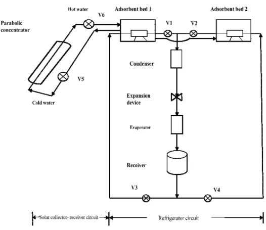
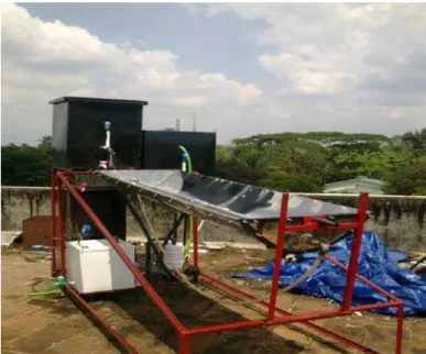
The single stage solar adsorption refrigeration system with a single adsorbent bed has the limitation that it can only be used in intermittent cycle with desorption in day time and adsorption in night time. To overcome this disadvantage, a two stage adsorption refrigeration system was developed, fabricated and tested at National Institute of Technology Calicut. The schematic of the system is shown in Fig. 1 and its photographic view is shown in Fig. 2. The solar adsorption refrigeration system has been tested under the meteorological conditions of Calicut (latitude of 11.15o N, longitude of 75.49o E) during April 2011.
The system utilises a common evaporator placed inside a refrigerator box, a condenser, an expansion device (capillary tube), parabolic solar concentrator, two adsorbent beds and two water tanks. The heating of water starts in the morning through the solar concentrator by natural circulation. With the increase in temperature of water in tank 1, the temperature in the adsorbent bed 1 increases. This causes the vapour pressure of the adsorbed refrigerant to reach up to the condensing pressure. When the pressure inside the adsorbent bed 1 is nearly equal to the condensing pressure the valve V1 is opened. The desorbed vapour is liquefied in the condenser. The high pressure liquid refrigerant is expanded through the expansion device to the evaporator pressure. The low pressure refrigerant then enters the evaporator, where the refrigerant takes the latent heat from water to be chilled and convert into the vapour refrigerant. The low pressure refrigerant vapour is stored in the accumulator.
Fig. 2 Photograph of the experimental set up
During night time bed 1 acts as the adsorber and bed 2 as the desorber. In the evening bed 2 is cooled down by cold water. When the pressure in the bed 2 is nearly equal to the evaporator pressure valve V4 is opened by keeping other valves V1, V2 and V3 closed. After the complete adsorption of refrigerant vapour the hot water from tank 1 is transferred to tank 2, which acts as a heat source for the night time. When the pressure in the bed 2 reaches to the condensing pressure the valve V2 is opened by keeping the valves V1 and V3 closed. The refrigerant passes through the condenser, expansion device and evaporator finally the refrigerant vapour is being stored in the accumulator. During this time the bed 1 acts as a adsorber which is cooled down by cooling water to the evaporator pressure so that it is ready for adsorbing the refrigerant stored in the accumulator.
2.2 Components
2.2.1 Parabolic solar concentrator
The function of the solar concentrator is to tap solar energy and this may be transferred to the water passing through the absorber tube. Parabolic solar concentrator of area 3 m2 made of stainless steel is used. The absorber consists of two concentric tubes. The inner tube is a copper tube and outer is glass. This is fixed along the focal line of the parabolic concentrator. The Photograph of the parabolic solar concentrator is shown in Fig. 3.
Fig. 3 Parabolic solar concentrator
2.2.2 Adsorbent bed and working pair
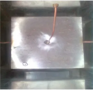
The adsorbent bed is as shown in Fig. 4. Both the beds are having the same size and are made of stainless steel. The dimensions of the beds are 400 mm x 400 mm x 180 mm. Activated carbon is selected as adsorbent material and methanol as the refrigerant (activated carbon-methanol pair) for the system. Each bed contains 3.5 kg of activated carbon.
Fig. 4 Adsorbent bed
2.2.3 Condenser
The condenser is a shell and coil type of capacity 200 W made of copper coils. The condenser is shown in Fig. 5.
Fig. 5 Condenser
In the condenser methanol vapour desorbed from the adsorbent bed is condensed by the water coming from the cooling tower.
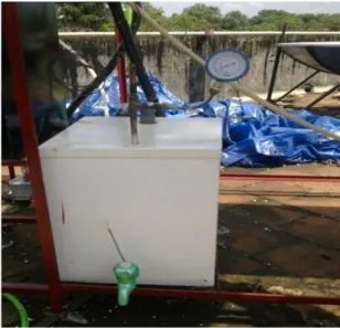
2.2.4 Evaporator
Fig. 6 Evaporator box 2.3 Measurements
A digital pyranometer with an accuracy of ±5 W/m2 is placed near the solar collector to measure the instantaneous solar insolation. Pressure is measured during heating (desorption) of refrigerant i.e. condensing pressure and during cooling (adsorption), i.e. evaporator pressure. The pressure gauges are fixed at the two adsorbent beds in order to measure the pressure inside the adsorbent beds at each stages of adsorption and desorption processes. The temperature at various points in the solar adsorption refrigeration system is measured by calibrated T-type (Copper – Constantan) thermocouples. The various points where temperatures observed are: (1) temperature of the two adsorbent beds during various processes, (2) temperature of the refrigerant at inlet and outlet of the condenser, expansion device and evaporator, (3) temperature of water entering the water tanks and (4) temperature of chilled water in the evaporator box.
3. Uncertainty analysis
Errors and uncertainties in the experiments can arise from the selection, condition and calibration of the instruments, environment, observation and test planning. A precise method of estimating uncertainty has been presented by Holman [3]. The method is based on a careful specification of uncertainties in the various primary experimental measurements. These measurements are then used to determine some desired results of the experiments. In the present study pressure, temperature and solar insolation are measured by using the instruments. The total uncertainty of the various calculated parameters is shown in Table 1 where as the calculation procedure is given in the Appendix 1.
Table 1 Uncertainty in different parameters
Description Total uncertainty (%)
COPcycle ±6.04% Heat input to the system ± 1.09% Solar cooling COP ±2.42% Exergetic efficiency ±5.48%
4. Performance parameters
The two most important parameters used for the performance measurement of adsorption refrigeration systems are cycle COP and specific cooling power [11].
4.1 Cycle COP
Cycle COP is defined as the ratio of cooling effect to the total energy required for desired cooling effect.
COP COP Q
Q (1)
The total energy input to the system is given by,
Cooling effect, Qe= mrg CPr (ΔTr) (3)
4.2 Specific cooling power (SCP)
Specific cooling power indicates the size of the system as it measures the cooling output per unit mass of adsorbent per unit time. Higher SCP values indicate the compactness of the system.
C
C
SCP Q
τ (4)
4.3 Solar COP
Since the system is solar powered the solar coefficient of performance is also to be defined. This is defined as the ratio of cooling effect to the net solar energy input.
Solar COP (5)
4.4 Exergetic efficiency
Exergetic efficiency E
Q TT (6)
(7)
5. Results and Discussion
5.1 Average values of performance parameters
Table II Average values of performance parameters
Parameters Day time Night time
Refrigerating effect (W) 60.75 79.87 Cycle COP 0.196 0.334 Theoretical COP 1.12 1.24 SCP (W/s-kg) 47.83 68.2
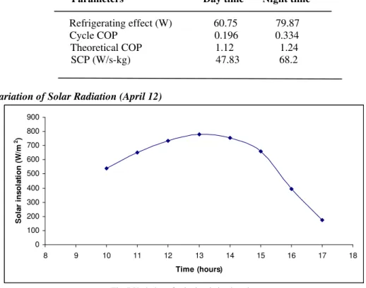
5.2 Hourly Variation of Solar Radiation (April 12)
Fig. 7 Variation of solar insolation in a day
Figure 7 shows the variation of solar insolation with time on a day of experiment. It is observed that the maximum solar insolation is 800 W/m2 which occurs at 13.00 hours. The variation is almost symmetrical about the constant time line 13.00 hours.
5.3 Variation of experimental cycle COP with chilled water temperature
0 100 200 300 400 500 600 700 800 900
8 9 10 11 12 13 14 15 16 17 18
Fig. 8 Variation of cycle COP during day time and night time with chilled water temperature
Figure 8 shows variation between the cycle COP during day time and night time with the different evaporator loads. COP during day time increases from 0.104 to 0.24 and during night time 0.245 to 0.44 as the chilled water temperature increases. Refrigeration effect and COP depends upon the mass of refrigerant desorbed. The mass of refrigerant desorbed for a particular time is less during day time than during the night time. At day time, desorption time is more as compared to night time, because during day time the time for isosteric heating and desorption is more due to the gradual increase of solar radiation from morning to noon. But during night time already hot water is available in water tank 2, so the time taken for isosteric heating and hence for desorption is less. At the day time the mass of the refrigerant desorbed is less and time taken for cooling increases. Also the amount of heat leakage into the system is more during day time as compared to the night time. Hence the net refrigeration effect during night time (57.6 W to 104.4 W) is more than during day time (48 W to 78 W) which leads to higher cycle COP during night time than during day time.
5.4 Variation of theoretical coefficient of performance
Figure 9 shows variation between theoretical COP and chilled water temperature. The theoretical COP during day time increases from 0.48 to 1.7 and during night time it varies between 0.52 and 2.5. The theoretical COP increases with evaporator loads because when the chilled water temperature increases the refrigerating effect increases due to increase in the exit enthalpy of the refrigerant.
5.5. Variation of Specific cooling power
Figure 10 shows the variation between SCP and chilled water temperature. Specific cooling power depends upon the refrigeration effect and cycle time for a fixed adsorbent mass. The cycle time for the day time (heating and desorption) is 210 minutes and for night time 110 minutes. Since the cycle time is less and refrigeration effect is more for the night time the specific cooling power is also more during night time compared to the day time.
Fig. 10 Effect of chilled water temperature on specific cooling power
5.6. Variation of SCP and COP with heat source temperature
From Fig. 11 it is seen that the heat source temperature has significant effect on COP and the SCP values. The coefficient of performance increases from 0.104 to 0.24 as the heat source temperature varies between 60oC and 90oC. This is because of the amount of refrigerant circulated increases due to increased refrigerant desorption with higher driving source temperature. The ascending dependency between the specific cooling power and heat source temperature can be explained by the fact that the high source temperature leads to a good desorption which is conducive to improvement in the adsorption refrigeration performance.
Fig. 11 Effect of heat source temperature on SCP and the COP of system
The SCP will be increased if the desorption temperature is increased in which case the high temperature solar heating is required.
Fig. 12 Solar cooling COP variation with chilled water temperature
Figure 12 shows the variation between solar cooling COP with chilled water temperature. The variation is similar to that of the cycle COP except in the magnitude. The Solar COP varies from 0.05 to 0.09 for different evaporator loads.
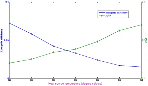
5.8 Variation of exergetic efficiency and cycle COP with the heat source temperature
From Figure 13 it is clear that the COP value increases with increase in heat source temperature but exergetic efficiency shows a different behaviour. The COP value depends upon the mass of adsorbate generated which in turn a function of heat source temperature.
Fig. 13 Effect of driving heat source temperature on exergetic efficiency and coefficient of performance
percentage of the applied heat is utilised for useful cooling is low. A large amount of heat is utilised for the wasteful heating of adsorbent and adsorbent bed material.
6. Conclusions
This work deals with a two stage solar adsorption refrigeration system which uses solar energy as input. An experimental system was installed and tested for analysing the performance. The performance parameters of the system are determined. The main conclusions reduced from the present study are given below:
(i) The two stage solar assisted adsorption refrigeration system has been developed for overcoming intermittency of the single bed system. It is found that the system is capable of operating in day time and night time with fairly good performance. The experimental results show that the system has an average refrigerating effect of 60.75 W during day time and 79.87 W during night time.
(ii) The mean cycle COP value is obtained as 0.196 during day time and 0.335 during night time. The mean values for specific cooling power for day and night time are 47.83 and 68.2, respectively.
(iii)The exergetic efficiency of the system is determined for different evaporator loads and the effect of heat source temperature on exergetic efficiency and coefficient of performance of the system is studied. The optimum heat source temperature for the system is found as 72.4oC
Nomenclature
Cp specific heat (kJ/kg K) COP coefficient of performance SCP specific cooling power
mass flow rate (kg/s)
p pressure (Pa)
T temperature (K)
rate of heat transfer (kW)
E exergy
S entropy
h enthalpy
rate of work transfer (kW)
Subscripts
1, 2, 3, 4 state points in the diagram
ads adsorption/adsorbent bed
des desorption
c cooling
cyc cycle
i/in inlet
o/out outlet
f fluid
a adsorbent r refrigerant s solar
Appendix A
The total uncertainty arising due to independent variables given by [8] is,
The result R is a given function in terms of independent variables. Let WR be the uncertainty in the result and w1 ,w2... wn be the uncertainties in the independent variables. COP of the system is a function of several variables each subject to an uncertainty
, ,
. 96
[12] Van Benthem GHW, Cacciola G, Restuccia G . Regenerative a d s o r p t i o n h eat
pumps: optimization of the design. Heat Recovery Systems & CHP 1995; 15(6):