Abstract— The condition for maximum power transfer of 2-coils wireless power transfer (WPT) system is derived from circuit analysis and discussed together with the respective WPT system efficiency (η). In the sequence, it is shown that a 4-coils WPT system (which can be divided in source, two communication and load circuits) without power losses at the two communication circuits (ideal 4-coils WPT system) presents, from maximum power transfer and efficiency point of view, a performance similar to those of a 2-coils WPT system. The exception is the influence of coupling coefficient (k): in 2-coils system η increases as k approaches one, while in ideal 4-coils WPT system η increases as k between the two communication coils approaches zero. In addition, realistic 4-coils WPT systems (with power losses at the two communication circuits) are also analyzed showing, for instance, that η presents a maximum as a function of k of the communication coils. In order to validate the presented theory, 4 coils were built, and a setup to perform 2-coils and 4-2-coils WPT systems has been carried out. Practical results show good agreement with the developed theory.
Index Terms— Maximum power transfer, power transfer efficiency, relative power transfer, wireless power transfer.
I. INTRODUCTION
Wireless power transfer (WPT) technology has been widely discussed in the last years [1–6]. For
instance, in a recent article the progress in mid-range WPT systems has been critically reviewed
discussing, among other topics, the importance of maximum power transfer (MPT) condition and
power transfer efficiency (η) in the design of these circuits [1]. However, a specific derivation of MPT
condition of WPT systems, from which their η could be properly addressed, was not presented.
The aim of this paper is to present the derivation of MPT conditions for 2-coils and 4-coils WPT.
Based on the derived MPT conditions, the systems efficiencies are discussed. The strategy adopted in
this work to show that the method used to derive the mentioned conditions is correct was to compare
its results, whenever possible, with classical MPT theorem conclusions. In this way, it is demonstrated
that the theoretical and practical results correspondent to 2-coils and theoretical result related to ideal
4-coils WPT (without power losses at the two communication circuits) systems are coherent with
classical MPT theorem conclusions. Of course, the real systems (with losses at communication coils)
differ from the ideal circuits, showing a maximum in the efficiency curve. Practical experimentations
Maximum Power Transfer versus Efficiency
in Mid-Range Wireless Power Transfer
Systems
Paulo J. Abatti, Sérgio F. Pichorim, and Caio M. de Miranda
Graduate School of Electrical Engineering and Applied Computer Sciences (CPGEI) Federal University of Technology - Paraná (UTFPR)
support the presented analysis.
II. CIRCUIT ANALYSIS
A. 2-Coils Circuit
Fig. 1 shows the equivalent circuit of a 2-coils WPT system.
Fig. 1. Schematic representation of a 2-coils power delivery system.
Considering both circuits tuned at the same resonance angular frequency ( = =
),
it can be written
= ± (1) and
0 = ± + (2)
where, M12 is the mutual inductance, R1 the total transmitting circuit resistance (including the internal
resistances of the source and those of the involved capacitance (C1) and inductance (L1)), and R2 the
total receiving circuit resistance (the sum of internal resistances of the involved capacitance (C2) and
inductance (L2) – r2– with the load resistance (RL)).
Electric power is calculated multiplying the resistance by the square of the current amplitude so that
using (1) and (2) it can be written
= (3)
and
= (4)
where, P1 and P2 are the electric power dissipated at R1 and R2, respectively.
Taking the derivative of (4) with respect to M12 and making the result equal to zero, after
manipulation, yields
= (5) This is the MPT condition for a 2–coils WPT system. (That (5) is a condition of maximum can be
demonstrated making the second derivative of (4) with respect to M12 equal to zero.) Moreover, using
i
1i
2v
L
1L
2C
1R
1M
12C
2(5) in (3) and (4) it leads to
= = . (6)
as classical MPT theorem teaches.
For comparison purposes it is interesting to compute the relative power transferred to R2 dividing
(4) by (6) which gives
!
!"#$ = (7)
Dividing the power transferred to R2 (P2) by the total power (P1+P2), the transmission efficiency (%)
can be calculate yielding
% = (8)
Note that, as also the classical MPT theorem teaches, using (5) in (8) gives % =1/2.
B. 4-Coils Circuit
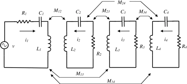
Figure 2 shows the equivalent circuit of a 4-coils WPT system.
Fig. 2. Schematic representation of a 4-coils power delivery system.
Considering all circuits tuned at the same resonance angular frequency = = =
& &= , and neglecting the influence of mutual inductances M13, M14, and M24, it can be written
= ' ( ± ' ( (9)
0 = '± ( + ' ( ± ' & &( (10) 0 = '± & ( + ' & &( ± ' & ( (11) and
0 = '± & &( + ' ( (12) where; M12, M23 and M34 are the mutual inductances, and R1, R2, R3 and R4 the total individual circuits
resistances. Note that R4 is, in fact, the sum of internal resistances of the involved capacitance (C4)
and inductance (L4) – r4 – with the load resistance (RL).
M
13i
1i
2v
L
1L
2C
1R
1M
12C
2Manipulating (9), (10), (11), and (12), the currents i1, i2, i3, and i4 can be calculated so that the
power dissipated at R1, R2, R3, and R4 can be written as
=)
(13)
= * ) (14)
&= * ) + & (15)
and
= + +,
* ) , (16)
respectively, where A, B, and C are given by
- = &+ ,+,
,
. = + +
,
and,
= + *
,
respectively.
Clearly, using the 2-coils WPT system as a guide, the powers P2 and P3 should be as small as
possible, so that, ideally, R2=R3=0.
Using the above condition (R2=R3=0) in (13), (14), (15), and (16), and remembering that mutual
inductance (in a general form Mxy) is defined as /0= 1/0 / 0 , where, kxy is the coupling
coefficient, ranging between zero and one [7], it can be written
= , 2 +
3 ,2 + 2 2+, 4 4,5
(17)
and
= 2 2 + 2+, 4 4, ,
3 ,2 + 2 2+, 4 4,5
(18)
with, evidently, P2=P3=0.
Taking the derivative of (18), also using 2-coils WPT system as a guide, with respect to k23 (M23
would be more general [8] but in 4-coils WPT system L2 and L3 appears in M12 and M34 and in (18)
they had been simplified) and making the result equal to zero yields
1 & = 1 1& (19)
This is the MPT condition for 4-coils WPT system without power losses at the communication
circuits. Note that using (19) in (17) and (18) gives
= = (20)
For comparison purposes here it is also interesting to compute the relative power transferred to R4,
dividing (18) by (20) yielding
!!, ,"#$ =
,2 2 + 2+, 4 4,
3 ,2 + 2 2+, 4 4,5
(21)
The system efficiency (%), also with R2=R3=0, can be defined as
% = !,
! ! !+ !,=
2 2+, 4 4,
,2 + 2 2+, 4 4, (22)
Note that, following the classical MPT theorem, using (19) in (22) gives % = 1/2.
However, in practice R2 and R3 are not usually negligible. In this case, relative power transferred to
R4 is given by
!!, ,"#$ =
, + +,
, + ' (' + , +, ( . (23)
whereas η is given by
% =' + +, ,
, + ' + , +, (( , + ' (' + , +, ( . (24)
Observe that, in case of R2=R3=0, (23) and (24) become (21) and (22), respectively. Moreover, it
can be seen that (23) and (24), due to their format, present a maximum. Thus, taking the derivative of
them with respect to k23 (as mentioned before, M23 would be more general [7] but in 4-coils WPT
system L2 and L3 appears also in M12 and M34) and making the results equal to zero yields
& = ' + (' & + & ( , (25) and
' & ( = ' + (' & + & ( , (26) respectively.
Observe that (25) and (26) show that the points of maximum of (23) and (24) are not coincident. In
addition, note that in case of R2=R3=0 (25) becomes (19), and (26) does not present a meaning
anymore, i.e., η does not have (in sense of derivative zero) a point of maximum. Finally, substituting
(25) in (23) and (26) in (24) it can be seen that the maximum in (23) and (24) is always, as expected,
less than one.
III. EXPERIMENTAL VALIDATION
For practical evaluation of the analysis presented in the previous section, a set of 4 coils, with equal
dimensions and shape, was constructed. The coils are circular with diameter of 150 mm and 20 mm of
length, wound with 22 turns of enameled copper 19 AWG wire in a single layer way. The coils
self-inductances have a similar measured value of 127 µH in the range of 10 to 800 kHz. All
measurements of inductances, capacitances, resistances, and resonance frequencies were obtained
using an Agilent precision vector impedance analyzer (4294A).
Since the presented analysis has a strong dependence on the coupling coefficient k, at first,
it has been used a Tektronix signal generator CFG253 to excite one coil, as primary, at a low
frequency of 10 kHz, to reduce the influence of the coils´ stray capacitances. Using an Agilent digital
oscilloscope MSO6034, the voltages were measured in the primary (v1) and in the open terminals of
the secondary coil (v2), while the distance between the coils was varied. Since the current in secondary
coil is zero, v1 = . : :;⁄ and v2 = . : :;⁄ . As the inductances are equal (L1=L2=L), then
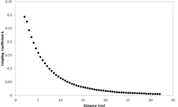
1 = / , after little manipulation it gives 1 = ⁄ . Fig. 3 shows the measured coupling
coefficient in a range of 2 to 32 cm (the distances are considered between the closer first turns).
Fig. 3. Measured coupling coefficient (k) as function of distance between two adjacent coaxial coils. Four coils with same
features: 150 mm of diameter, 20 mm of length, 22 turns of copper wire with diameter 0.9 mm.
To achieve the same resonant frequency at four coils, precision capacitors of 560 pF were used. In
fact, in a set of 20 capacitors, 4 were selected by measuring their capacitances (all around 575 pF). It
is important to note that even using precision capacitors, each capacitor was chosen specifically for
each coil´s inductance, since the inductances also have small variations. In this way, it was possible to
select the resonant frequency of 589 kHz with a precision of 100 Hz for the 4 coils. After tuning, the
total internal series resistances RS of the LC circuit, at the resonant frequency of 589 kHz, were
measured, resulting in similar values of 3.3 Ω.
To measure the relative power transfer and efficiency, it is necessary to know the currents in coil 1
and in the load. In this way, a shunt resistor (R0) of 10 Ω was used in series with coil 1 in all the
measurements (the measured resistance value was 9.85 Ω at 589 kHz). Three different loads (Rl)
values were used 10, 50, and 100 Ω (exact values of 9.85, 49.7 and 100.24 Ω). All resistor presented
measured stray inductances of 40 nH at 589 kHz.
A voltage signal (vG) of 7.7 VRMS with 589 kHz was applied on coil 1. To confirm that the resonant
frequency has not been changed by external influences of the setup, such as cable capacitances and
primary circuit (a single isolated coil). Another important parameter is the internal impedance of the
signal generator RG. This impedance is in series with coil 1 and contributes to the total series
resistance. The exact measured value of RG was 48 Ω. With all of these parameters taken into account,
it is possible to calculate the total resistance R1 of 61.15 Ω (R0 + RS + RG). The total load resistance RL
was Rl + RS. The voltages on R0 and Rl were measured for different distances between the coils. So,
the currents in primary circuit and load, i1 and il, respectively, could be found. Finally, the dissipated
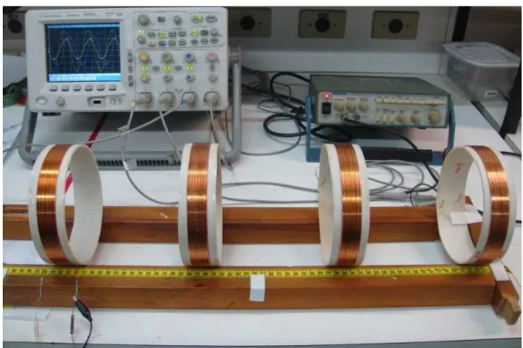
power at primary is = ⋅ and at RL is 4= 4⋅ > . Fig. 4 shows the setup used in the
experiments.
Fig. 4. Setup used for experimentation, showing the oscilloscope, signal generator and, in the bottom, the 4 constructed coils.
A. 2-Coils Circuit Results
For 2-coils WPT system, the measured efficiency was given by P1/(P1+PL) and relative power
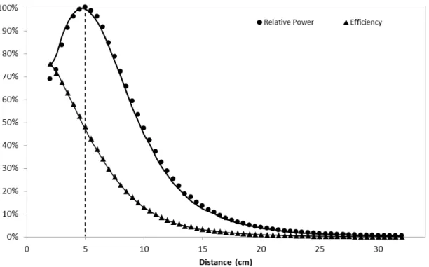
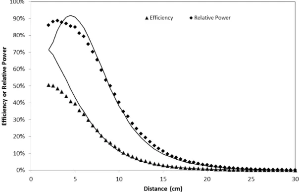
transferred by PL/P2MAX. The calculated values are given by (8) and (7), respectively. Fig. 5 presents
the measured and calculated values of the efficiency and relative power for 100 Ω of load. Distance
ranging from 2 to 32 cm. The dashed line points the maximum power transfer, for which efficiency is
Fig. 5. Practical (points) and theoretical (solid line) comparisons between efficiency and relative power (P2/P2MAX) as
function of distance between coils (for 2-coils set), for a load of 100 Ω (R2 total of 103.54 Ω). Dashed line marks maximum
power and efficiency of 50% at distance of about 5 cm.
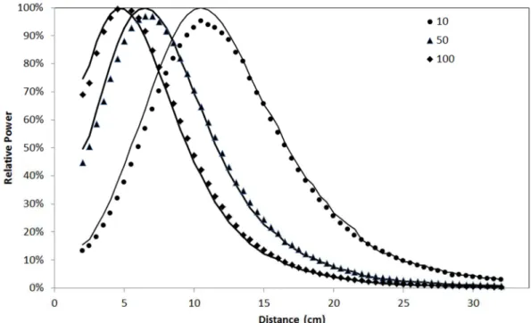
A comparison for three different loads values is presented in Fig. 6 and 7, for measured and
calculated values of the efficiency and relative power, respectively. Maximum power transfers were
registered for distance of 5, 6.5, and 10.5 cm for loads of 100, 50, and 10 Ω, respectively.
Fig. 6. Efficiency as function of distance between coils (for 2-coils set). Dots are measured values for loads of 10, 50, and
Fig. 7. Relative power (P2/P2MAX) as function of distance between coils (for 2-coils set). Dots are measured values for loads
of 10, 50, and 100 Ω (R2 total of 13.15, 53, and 103.54 Ω, respectively). Solid curves are calculated using (7).
B. 4-Coils Circuit Results
In 4-coils WPT system, measured efficiency could be given by the relation PL/(P1+P2+P3+PL).
However, the resistances R2 and R3 are not external resistors, so P2 and P3 could not be measured
directly. Thus, considering that all the power, delivered by the generator PG, is dissipated by ohmic
losses, the efficiency can be alternatively calculated by PL/PG, where PG = vG⋅i1. Theoretical values
are calculated using (23) and (24).
Several different coils arrangements can be conducted with 4-coils WPT systems. Here two
approaches are presented. First, it was imposed the same distance between adjacent coils in a range of
2 to 32 cm between them, yielding k12 = k23 = k34. The results for the efficiency and relative power
transferred for a load of 100 Ω are given in Fig. 8. Maximum power was measured at distance of 3
cm, whereas the calculated distance is 5 cm.
It can be noted that for distances smaller than approximately 5 cm the inter-couplings
between non-adjacent coils (k
13, k
14, and k
24different from zero) introduce errors, so that
theoretical and practical results are not equal to each other. This is in agreement with the
theory presented since the influence of non-adjacent coils (k
13, k
14, k
24) are not considered in
Fig. 8. Efficiency and relative power (P4/P4MAX) as function of distance (for 4-coils set). All coils were kept at the same
distance (k12 = k23 = k34). Values were measured (points) and calculated (solid curve) through (23) and (24) for a load of 100
Ω (R4 total of 103.54 Ω).
The second approach was to keep the distances between coils 1 and 2, and coils 3 and 4 constant at
10 cm, varying only the distance between coils 2 and 3 [2]. In this way, the interference between
non-adjacent coils can be neglected. Calculated efficiency and relative power (P4/P4MAX) in function of
distance and practical results are presented in the solid curves and dots of Fig. 9, respectively. A
maximum efficiency of 29.14% was obtained at 18.5 cm while the calculated was 29.12% at 18 cm.
For maximum power transfer, a value of 59.17% at 14.5 cm was measured and 59.31% at 15 cm was
calculated. Note that, in the ideal case (without losses in coils 2 and 3, i.e. R2=R3=0), efficiency will
increase as the distance between coils 2 and 3 increases, as previewed in the developed theory (see
dashed line in Fig. 9). This behavior is opposite to the 2 coils arrangement. For real situations,
maximum efficiency occurs for longer distances than maximum power point (as seen in (25) and
(26)), or 18 cm and 15 cm, respectively, in this experimentation.
It is important to point out that theoretical values of Fig. 5 to 9 were calculated using practical
values of coupling coefficient (k), which were obtained in Fig. 3. Therefore, small irregularities can be
observed in the curves. However, these insignificant errors cannot compromise the validity of this
Fig. 9. Measured (points) and calculated (solid line) through (24) and (23) efficiency (η) and relative power (P4/P4MAX) as
function of distance between coils 2 and 3 with 100 Ω (R4 total of 103.54 Ω). Distances between coils 1 to 2 and coils 3 to 4
were constant at 10 cm. Dashed and dotted lines are simulated η and P4/P4MAX for ideal case (R2=R3=0) using (22) and (21),
respectively.
IV. CONCLUSION
The MPT conditions of 2-coils and 4-coils WPT system have been derived from circuit analysis and
discussed together with the respective system power transfer efficiency, demonstrating that 4-coils
system with R2=R3=0 presents, from maximum power transfer and efficiency point of view, a
performance similar to those of a 2-coils system. The exception is the influence of coupling
coefficient: in 2-coils system η increases as k12 approaches one, while in 4-coils system η increases as
k23 approaches zero. Obviously, the condition R2=R3=0 is not attainable in common practical circuits,
being used in this work only as a theoretical guide to allow the comparison between 2-coils and
4-coils WPT.
In fact, usually a 4-coils WPT system presents power losses at R2 and R3. For this condition, it has
been also demonstrated that 4-coils WPT system has, as expected, its ability to transfer power to the
load and its efficiency reduced as power losses at R2 and R3 increase. Here it is important to emphasize
that, from efficiency point of view, a 2-coils or a 4-coils WPT system with R2=R3=0 are different
from a 4-coils WPT system with power losses at R2 and R3 since the later presents a maximum
efficiency as a function of k23.
Note that in a series circuit classical MPT theorem teaches that if RSOURCE=RLOAD, power transferred
to the load is maximum and η is ½, and that, keeping RSOURCE constant, η increases as RLOAD increases.
aim is to increase η (obviously, RLOAD=∞ implies η=1, however the power transferred to the load is
zero). What the presented analysis demonstrated and practical results validated is that, starting from
MPT condition (see (19) or (25)), the designer must reduce k23 (instead of increase k23 - at a first
glancea more intuitive decision) if his or her aim is to increase η of a 4-coils WPT system with
R2=R3=0 or to optimize η of a 4-coils WPT system with R2 and R3 ≠ 0, since in this case η presents a
maximum as a function of k23 (see (26)).
Very high Q-factor coils were recommended in previous works to achieve high power transfer
efficiency with low coupling coefficient (k → 0) [1–6]. As Q-factor is a fraction '?/= 4@
@ (, clearly,
it can be increased by decreasing the denominator or increasing the numerator. However, by
increasing ωo, one is increasing all mutual inductances values and, consequently, reducing the power
transferred to the load (see (21) and (23)), so that in the limit P4=0 for any value of k23. (Of course, to
increase L2 and L3 also increase M12, M23 and M34 which reduces P4 of 4-coils WPT system with R2
and R3 ≠ 0). In fact, the only manner to increase Q2 and/or Q3, to enhance power transfer efficiency,
without disturb the other parameters is to decrease R2 and/or R3, respectively. Because of this, the
authors decided do not use Q-factor concept in the equations.
Practical measurements had good agreement with the proposed analysis, either for 2-coils and
4-coils WPT circuit. Differences appear when 4-coils are too close, because non-adjacent 4-coils´ coupling
coefficient cannot be neglected. Of course, it must be emphasized that if M13 and/or M14 and/or M24 are
significant, the presented analysis is clearly not valid anymore (see Fig. 8).
Finally, for 4-coils WPT circuit with ohmic losses in the communication coils (L2 and L3), as shown
by (23) and (24), maximum η and P4/P4MAX points are not coincident. The first one occurs when coils
are further to each other than the second one.
The authors hope that the presented circuit analysis can be useful for those involved in the
design/implementation of 2-coils or 4-coils WPT systems, including the power electronics necessary
to drive them.
ACKNOWLEDGMENT
The authors would like to thank Brazilian Council for Scientific and Technological Development
(CNPq) and Brazilian Council for the Improvement of Higher Education (CAPES) for partial
REFERENCES
[1] S.Y.R. Hui, W.X. Zhong, and C.K. Lee, “A Critical Review of Recent Progress in Mid-Range Wireless Power Transfer,” IEEE Trans. Power Electronics, vol. 29, no. 9, pp. 4500-4511, Sept. 2014.
[2] A. Kurs, A. Karalis, R. Moffatt, J. D. Joannopoulos, P. Fisher, and M. Soljacic, “Wireless power transfer via strongly coupled magnetic resonances,” Science, vol. 317, no. 5834, pp. 83–86, Jul. 2007.
[3] A. L. Sample, D. A. Meyer, and J. R. Smith, “Analysis, Experimental Results, and Range Adaptation of Magnetically Coupled Resonators for Wireless Power Transfer,” IEEE Trans.Ind. Electron. vol. 58, no. 2, pp. 544-554, Feb. 2011. [4] A. K. RamRakhyani, S. Mirabbasi, and M. Chiao, “Design and optimization of resonance-based efficienct wireless
power delivery systems for biomedical implants,” IEEE Trans. Biomedical Circuits and Systems, vol. 5, no. 1, pp. 48-63, Feb. 2011.
[5] M. Kim, K. Koo, S. Ahn, B. Bae, and J. Kim, “Analytical Expressions for Maximum Transferred Power in Wireless Power Transfer Systems,” in Proc. EMC 2011, pp. 379-383.
[6] A. K. RamRakhyani and G. Lazzi, “On the Design of Efficient Multi-Coil Telemetry System for Biomedical Implants,”
IEEE Trans. Biomedical Circuits and Systems, vol. 7, no. 1, pp. 48-63, Feb. 2013.
[7] P. J. Abatti, S. F. Pichorim, and B. Schneider Junior, “A method to derive mutual inductance properties using electric circuit analysis tools,” International Journal of Electrical Engineering Education, vol. 45, pp. 46-50, 2008.
[8] S. F. Pichorim and P. J. Abatti, “Design of Coils for Millimeter- and Submillimeter-Sized Biotelemetry,” IEEE Trans