Fiabilitate si Durabilitate - Fiability & Durability No 2/ 2012
Editura “Academica Brâncuşi” , Târgu Jiu, ISSN 1844 – 640X
25
LASER CUTTING MACHINES FOR 3-D THIN SHEET PARTS
Dr. Miroslav RADOVANOVIC, assoc. professor Faculty of Mechanical Engineering - Nis, Yugoslavia
Abstract. Laser cutting machines are used for precise contour cutting thin sheet. In industrial application
nowadays various types and construction of laser cutting machines can be met. For contour cutting 3-D thin sheet parts laser cutting machines with rotation movements and laser robots are used. Laser generates the light beam, that presents a tool in working process. Application of laser cutting machines made possible good quality of products, flexibility of production and enlargement of economy.
Keywords: cutting, laser, optical system, injection
1. Introduction
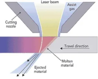
The production of laser cutting machines began thirty years ago. The progress was very fast and at present time every year over 3000 laser cutting machines are installed in the world. Laser cutting is one of the largest applications of lasers in metal working industry. It is based on vaporize the material in a very small area by focused laser beam. Process characteristics are: uses a high energy beam of coherent light; beam is focused on an small spot on the work piece by a lens; focused beam melts, vaporizes, or combusts material; molten material is ejected out from the melt area by pressurized gas jet. Laser cutting is the high speed cutting with a narrow kerf width that results in superior and enhanced quality, higher accuracy and greater flexibility. In fig. 1 schematic is shown the laser cutting.
Fig. 1: Laser cutting
Fiabilitate si Durabilitate - Fiability & Durability No 2/ 2012
Editura “Academica Brâncuşi” , Târgu Jiu, ISSN 1844 – 640X
26
2. Laser cutting machines
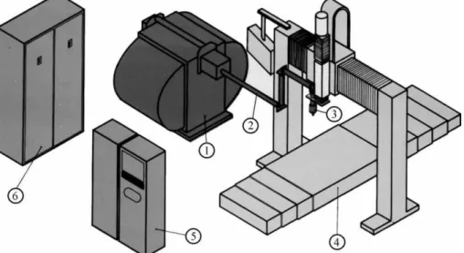
Laser machines for contour cutting thin sheet present the product of high technology. They are composed of: laser, beam guiding, cutting head, coordinate table, system for energy supply and control unit. In fig. 2 is shown the basic configuration of laser cutting machine.
Fig. 2: The basic configuration of laser cutting machine:
1-laser, 2-beam guiding, 3-cutting head, 4-coordinate table, 5-control unit, 6-system for energy suply
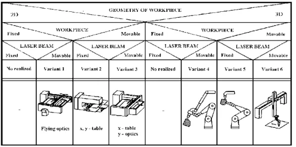
Laser, the optical quantum generator, generates the light beam, that presents a tool in working process. By optical system in cutting head the laser beam is focused in diameter from 0,2 mm with the power density over 108 W/cm2. Since our desire is to remove the evaporated and molten material from the affected zone as soon as possible, the laser cutting is performed with a coaxial assist gas. The gas blowing increases the feed rate for as much as 40 %. Cutting process along contour is realized with the movement of laser beam or workpiece. Machine for movements is an accordance with necessity's of laser machine. For variety of work laser machine have a support tables who can be supplied: a simple cutting grid, a cutting table with transportable and removable pallets and a change-over table.
Fiabilitate si Durabilitate - Fiability & Durability No 2/ 2012
Editura “Academica Brâncuşi” , Târgu Jiu, ISSN 1844 – 640X
27
Fig. 3: Variants of laser cutting machines
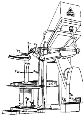
For contour cutting 3-D thin sheet parts, rotation movements are added to laser cutting machines. Rotation movements are realized by rotation of cutting head or by rotation workpiece by added devices on worktable, fig. 4.
Fig. 4: Laser cutting machines for 3-D parts
Fiabilitate si Durabilitate - Fiability & Durability No 2/ 2012
Editura “Academica Brâncuşi” , Târgu Jiu, ISSN 1844 – 640X
28
3. Laser robots
Modern laser cutting robots have a totally flying optics architecture. All movements are made by the focusing head and the workpiece remains stationary. Laser robot takes the laser beam along any continuous pre-programmed path in three-dimensional space, then cuts with accuracy, speed and quality. The speed and acceleration on the main axes of the new generation of robotic systems are 60 m/min and 23 m/s2. Integration of the laser beam guiding in the robot arm structure offers great advantages compared to conventional systems with external laser beam guiding. All limitations of the accessibility to dimensional components are eliminated due to the high movability and the compact design of the slim hand articulation module. Due to the centre outlet of the laser beam on the wrist, the 6th axis of the robot may be omitted, and the free space can be used for passage of the beam. This solution offers the following advantages: compact construction of the robot hand articulation, very good accessibility to 3-dimensional components, favourable work envelope and high degree of freedom of motion, high cutting speeds, high path accuracy and economic price. In fig. 5 is shown the laser robot.
Fig. 5: Laser robot
Fiabilitate si Durabilitate - Fiability & Durability No 2/ 2012
Editura “Academica Brâncuşi” , Târgu Jiu, ISSN 1844 – 640X
29
Special software that permits accommodation of coordination laser power with cutting speed are present and desirable. Programming is carried out in collaboration with an off-line system by means of a personal computer. More and more systems are requested to be interfaced with various CAD/CAM systems. The most applicable laser robots are laser robot with Nd:YAG Laser and laser robot with CO2 laser. For Nd:YAG laser, beam guiding is
performed from a stationary high-performance Nd:YAG laser with up to 4 kW beam capacity via a flexible light cable in the upper arm of the robot up to the forced air cooled hand axis. The fiber optic cable is mounted here via a connector plug on the hand axis. The diverging laser beam emitted from the fiber optic cable are guided to the outlet opening at the hand axis via two integrated deviation mirrors.
The deviation mirrors are designed as high-reflective coated quartz substrates. The exact position of the beam axis relative to the movement axis is adjusted via adjusting elements on the deviation mirrors. Collimation and focussing of laser beam is performed at the outlet opening of the hand axis via flange-mounted modules that can be flexibly adapted to the processing task. Application fields of Nd:YAG laser robot are: cutting of sheet metal components made of steel, stainless steel, aluminium; welding and soldering of sheet metal components made of steel, stainless steel, aluminium; welding of thermoplastic materials; hardening tool steels; build-up welding with wire and powder filler metal.
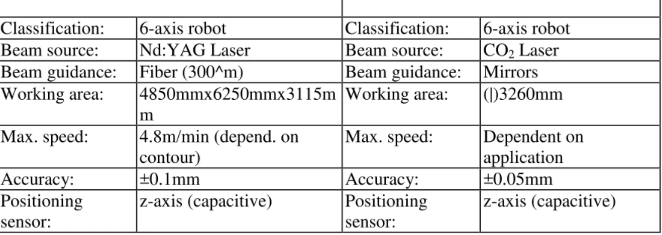
Table 1: Example of characteristics of laser robots
Classification: 6-axis robot Classification: 6-axis robot Beam source: Nd:YAG Laser Beam source: CO2 Laser
Beam guidance: Fiber (300^m) Beam guidance: Mirrors Working area: 4850mmx6250mmx3115m
m
Working area: (|)3260mm
Max. speed: 4.8m/min (depend. on contour)
Max. speed: Dependent on application
Accuracy: ±0.1mm Accuracy: ±0.05mm
Positioning sensor:
z-axis (capacitive) Positioning sensor:
z-axis (capacitive)
The CO2 laser is directly mounted adjustably on the upper arm of the robot with a mounting bracket. The beam exit of the laser is pointing opposite to the hand axis of the robot. Via two adjustable deviation mirrors made of surface-coated silicon the laser beam is coaxially guided into the fourth robot axis. Directly on the hand axis there is rigidly mounted a beam
staggering module with two silicon deviation mirrors that guides the beam coming from the fourth axis to the first deviation mirror of the hand axis. Beam guiding in the hand axis is structured similar to the version for the Nd:YAG laser. Instead of the quartz substrates
surface-coated silicon mirrors are used. At the outlet end of the hand axis there is mounted the cutting head where exact adjustment of the beam focus position as well as the position of the cutting nozzle via adjusting elements is possible. Application fields of CO2 laser robot are:
Laser-Fiabilitate si Durabilitate - Fiability & Durability No 2/ 2012
Editura “Academica Brâncuşi” , Târgu Jiu, ISSN 1844 – 640X
30
robot has brought about various improvements in quality, reduced costs and working times. The industries listed above use laser robots for:
• Prototyping, an activity which normally costs a car manufacturer thousands of hours per year (the parts to be produced range from single pieces to a few dozen for experimental pre-production runs).
• Production in small batches, luxury or special cars, trucks and buses or parts for the aerospace industry.
• Production of spare parts where the robot flexibility is especially suited to following the diversified demand.
• For cutting and drawing dies. The process of development that precedes the die forming reaps a major advantage when laser robots are used.
• Cutting of large turbine blade ving contours for rotors and stators.
Flexibility of the systems is often the most important reason for its purchase since in the case of production start-up or small batch production, frequent modifications will be necessary.
4. Conclusion
Laser cutting machines for 3-D thin sheet parts can be conventional laser cutting machines with rotation movements and laser robots. By conventional laser cutting machines rotation movements are realized by rotation of cutting head or by rotation workpiece by added devices on worktable. Laser robots are used for contour cutting 3-D thin sheet parts. Their characteristics is possibility of linear and rotate movement and change in orientation.. Laser robots are characterised by quiet work, precision and possibility of computing and that is decisively they to replace successively conventional cutting machines.
References
[1] Introduction to Industrial Laser Materials Processing, Rofin-Sinar Laser, Hamburg, 2000 [2] Eversheim W., Lasergerechte Konstruktion und Fertigung, VDI-Verlag, Dusseldorf, 1992 [3] Laser robot cuts and welds, Sheet Metal Industries, October, 1988, p.549-550
[4] Lazarevic, D., Radovanovic, M.: Nonconventional Methods; Metal Forming by Removal, Mechanical Engineering Faculty, Nis, Yugoslavia, 1994
[5] Radovanovic M., Lazarevic D., Laser Machines and Laser Robots for Cutting Thin Sheet, International Conference on Mechanical Transmissions and Mechanisms - MTM'97, Tianjin, China, 1997, p.867-870
[6] Radovanovic M., Application of Lasers in Manufacturing, 4th International Conference on Accomplishments of Electrical and Mechanical Industries, Banja Luka, Bosna&Hercegovina,
2001, p. 169-174
[7] Morel M., Robots tackle laser cutting, March, 2000, www.industrial -lasers.com [8] Radovanovic M., Laser Machines for Contour Cutting and Their Influence on Working Quality, 6th ICTP, International Conference on Technology of Plasticity, Nuremberg, Germany, 1999, p.729-730