Vitor Manuel Freitas Nóbrega
MESTRADO EM ENGENHARIA INFORMÁTICA
janeiro | 2014
W
AMM
Wiki
Aided Meta Modelling
V
itor Manuel Freitas Nóbrega
DM
WAMM
Wiki Aided Meta Modelling
DISSERTAÇÃO DE MESTRADO
DIMENSÕES: 45 X 29,7 cm
PAPEL: COUCHÊ MATE 350 GRAMAS
IMPRESSÃO: 4 CORES (CMYK)
ACABAMENTO: LAMINAÇÃO MATE
NOTA*
Caso a lombada tenha um tamanho inferior a 2 cm de largura, o logótipo institucional da UMa terá de rodar 90º ,
para que não perca a sua legibilidade|identidade.
Caso a lombada tenha menos de 1,5 cm até 0,7 cm de largura o laoyut da mesma passa a ser aquele que consta
no lado direito da folha.
Nome do Projecto/Relatório/Dissertação de Mestrado e/ou T
ese de Doutoramento |
Nome
do
Autor
ORIENTADOR David Sardinha Andrade de Aveiro
Vitor Manuel Freitas Nóbrega
MESTRADO EM ENGENHARIA INFORMÁTICA
WAMM
Wiki Aided Meta Modelling
I
Abstract
All over the world, organizations are becoming more and more complex, and there’s a
need to capture its complexity, so this is when the DEMO methodology (Design and
Engineering Methodology for Organizations), created and developed by Jan L. G. Dietz,
reaches its potential, which is to capture the structure of business processes in a
coherent and consistent form of diagrams with their respective grammatical rules.
The creation of WAMM (Wiki Aided Meta Modeling) platform was the main focus of
this thesis, and had like principal precursor the idea to create a Meta-Editor that
supports semantic data and uses MediaWiki.
This prototype Meta-Editor uses MediaWiki as a receptor of data, and uses the ideas
created in the Universal Enterprise Adaptive Object Model and the concept of Semantic
Web, to create a platform that suits our needs, through Semantic MediaWiki, which
helps the computer interconnect information and people in a more comprehensive,
giving meaning to the content of the pages.
The proposed Meta-Modeling platform allows the specification of the abstract syntax
i.e., the grammar, and concrete syntax, e.g., symbols and connectors, of any language,
as well as their model types and diagram types. We use the DEMO language as a
proof-of-concept and example.
All such specifications are done in a coherent and formal way by the creation of
II
Keywords: Organizational Engineering, DEMO Methodology, Semantic MediaWiki,
SVG-Edit, SVG meta-editor, UEAOM.
Acronyms:
SMW - Semantic MediaWiki
SVG - Scalable Vector Graphics
DEMO - Design & Engineering Methodology for Organizations
III
Resumo
Em todo o mundo, as organizações estão se tornando cada vez mais complexas, e existe
a necessidade de capturar a sua complexidade, e é quando a metodologia DEMO
(Design e Metodologia de Engenharia de Organizações), criada e desenvolvida por Jan
LG Dietz, atinge o seu potencial, que é o de capturar a estrutura de processos de
negócios de uma forma coerente e consistente na forma de diagramas com as suas
respetivas regras gramaticais.
A criação da plataforma WAMM (Wiki Meta Aided Modeling) será o foco principal
desta tese, e teve como principal precursor a ideia de criar um meta-editor que suporte
dados semânticos e utilize o MediaWiki.
Este protótipo Meta-Editor usa o MediaWiki como recetor de dados, e usa as ideias
criadas no Universal Enterprise Adaptive Object Model e o conceito de Semantic Web,
para a criação de uma plataforma que se adapte às nossas necessidades, através do
Semantic MediaWiki, o qual ajuda o computador a interligar a informação e as pessoas
de uma forma mais compreensiva, dando significado ao conteúdo das páginas.
A plataforma de Meta-modelagem proposta permite a especificação da sintaxe abstrata,
isto é, a gramática e a sintaxe concreta, por exemplo, de símbolos e conectores, de
qualquer linguagem, tal como os seus tipos de modelos e de diagramas. A linguagem
DEMO é utilizada como prova do conceito e exemplo.
Todas as especificações são feitas de forma coerente e formal, através da criação de
IV
Palavras-chave: Engenharia Organizacional, Metodologia DEMO, MediaWiki
Semântico, SVG-Edit, SVG meta-editor, UEAOM.
Acrónimos
SMW - MediaWiki Semântico
SVG - Gráficos vetoriais escaláveis
DEMO - Design & Metodologia de Engenharia para Organizações
V
Contents Index:
Abstract ... I
Resumo ... III
Contents Index: ... V
Table Index: ... VI
Figures Index: ... VII
1 Introduction ... 1
1.1 Motivation ... 7
1.2 Objectives ... 8
1.3 Content ... 9
2 Related work & problem ... 10
2.1 SVG or Canvas Graphical editor type ... 10
2.2 Scalable Vector Graphics (SVG) ... 11
2.2.1 SVG graphical editor ... 12
2.3 Meta modeling ... 13
2.4 Meta-Editor ... 14
3 Context ... 15
3.1 Enterprise Ontology Theoretical Concepts ... 15
3.1.1 Enterprise Ontology ... 15
3.1.2 Factual knowledge ... 15
3.1.3 Stata and Facta ... 17
3.1.4 World Ontology ... 18
3.1.5 The Grammar of WOSL ... 19
3.2 Basic Ontological Notions ... 20
3.3 Theoretical Foundations on Models ... 24
3.4 The universal enterprise adaptive object model... 25
3.4.1 Abstract Syntax ... 26
3.4.2 Concrete Syntax ... 30
3.5 EE tools supporting DEMO ... 33
3.6 Realizing OSA with a wiki ... 35
3.6.1 Fundamental patterns used ... 36
3.6.2 Creating models and diagrams ... 37
3.6.3 Page names and semantic properties ... 39
3.6.4 Semantic Forms ... 41
4 Implementation ... 43
4.1 MediaWiki ... 46
4.2 Configuring and installing MediaWiki ... 46
VI
4.2.2 Parser hooks: ... 47
4.2.3 Additional extensions ... 47
4.2.4 Parametization ... 48
4.3 Semantic Web ... 50
4.4 Defining wiki pages and semantic properties ... 50
4.5 Templates and properties ... 52
4.5.1 Templates examples ... 56
4.6 Templates and categories: ... 58
4.7 Template for elements ... 60
4.8 Forms and templates ... 63
4.8.1 Form: OAKRK ... 64
4.8.2 Form: OAK-Organizational Artifact Kind ... 66
4.8.3 How to use the Forms and edit pages ... 67
4.9 Page names, templates and properties connections ... 69
4.10 Creating MediaWiki extensions ... 74
4.11 SVG-edit ... 75
4.11.1 SVG-Edit – Connector point extension ... 76
4.11.2 SVG-Edit MediaWiki toolbar ... 77
4.11.3 SVG-Edit MediaWiki toolbar use procedure ... 77
4.11.4 SVG-Edit attributes ... 81
4.11.5 SVG-Edit procedures for creating shape kind ... 84
4.11.6 SVG-Edit modifications ... 85
4.12 Connector-Edit ... 87
4.12.1 Connector-edit implementation ... 91
4.12.2 Adapting extension Anywebsite for Connector-Edit ... 95
5 General Arquitecture ... 96
6 Conclusion ... 97
7 Bibliography ... 99
8 Appendix ... 101
Table Index:
Table 1 - Comparison between SVG and Canvas ... 10Table 2 - Semantic properties examples ... 52
Table 3 - Template properties specification examples ... 55
Table 4 - Templates and category for each... 59
Table 5 - Elements and their attributes ... 60
Table 6 - SVG-Edit file names, description and changes done ... 85
Table 7 - Connector kind template properties specification ... 89
VII
Figures Index:
Figure 1 - Simplified version of the UEAOM ... 1
Figure 2 - SVG-Edit interface ... 4
Figure 3 - Connector Edit interface ... 4
Figure 4 – Examples of pages created in the Meta-Editor with their specific interconnections ... 6
Figure 5 - Performance Comparison between Canvas and SVG [3] ... 11
Figure 6 - The meaning triangle ... 16
Figure 7 - The ontological parallelogram ... 17
Figure 8 - Statum type declarations ... 19
Figure 9 - Example of a reference law ... 19
Figure 10 - Example of a dependency law ... 20
Figure 11 - Example of a factum type ... 20
Figure 12 - The meaning triangle 2 ... 21
Figure 13 - The ontological parallelogram 2 ... 21
Figure 14 - The model triangle ... 21
Figure 15 - Model triangle applied to organizations ... 21
Figure 16 - Meaning triangle applied to a transaction OA ... 21
Figure 17 - Model triangle applied to the organization space ... 21
Figure 18 - Type Square ... 25
Figure 19 - Universal Enterprise Adaptive Object Model ... 28
Figure 20 - UEAOM - Abstract Syntax classes ... 29
Figure 21 - DEMO Ontological Meta-Model and UAOM classes used to represent it . 29 Figure 22 - UEAOM Concrete syntax ... 30
Figure 23 - DEMO concrete diagrams example and UEAOM classes used to represent them ... 32
Figure 24 - Overview of the SMW Pages and their Relation with DEMO Models and UEAOM ... 35
Figure 25 - Semantic box for CA02-driver_shape ... 39
Figure 26 - DIAGRAM TEMPLATE page view ... 41
Figure 27 - DIAGRAM TEMPLATE edit view ... 42
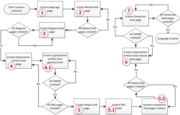
Figure 28 - Fluxogram of the creation protocol ... 43
VIII
Figure 30- MediaWiki installed software ... 46
Figure 31 - Semantic extensions installed ... 47
Figure 32 - Parser hooks installed ... 47
Figure 33 - Other extensions installed ... 47
Figure 34 –WikiEditor interface ... 48
Figure 35 - File page with PNG version ... 49
Figure 36 - Original SVG File ... 49
Figure 37 – Menu for creating semantic Property with Type options ... 50
Figure 38 - Overview of page Property: End connector symbol position ... 51
Figure 39 - List of Templates created in MediaWiki ... 53
Figure 40 - Template: LANGUAGE page edit ... 54
Figure 41 - Template Structure for Organizational artifact kind relation kind ... 56
Figure 42 - Template Structure for Organizational artifact kind ... 57
Figure 43 - Template Structure for Organizational artifact kind element kind ... 57
Figure 44 - Template Structure for Diagram kind ... 57
Figure 45 - Template structure for Connector ... 57
Figure 46 - UEAOM with the template definition for each class ... 58
Figure 47 - Template: SHAPE... 62
Figure 48 – Component Templates with their associated Categories ... 62
Figure 49 - List of Forms that exist in MediaWiki ... 63
Figure 50 - Form: OAKRK page creator ... 64
Figure 51 - Form: OAK page creator ... 67
Figure 52 – Special pages - page ... 68
Figure 53 - Form link page example ... 68
Figure 54 - Form Edit for OCD page ... 69
Figure 55 - Pages names, templates and properties connections ... 70
Figure 56 - Rent a car, ATD example with the selected part used for example ... 71
Figure 57 – Pages created for Rent a car example and interconnection between pages-1stpart ... 72
Figure 58 - Pages created for Rent a car example and interconnection between pages- 2ndpart ... 73
Figure 59 - Form: Shape kind ... 78
Figure 60 - Shape kind page example ... 78
IX
Figure 62 - Shape kind page with SVG-edit application open ... 79
Figure 63 - Shape kind edit page – example code created ... 80
Figure 64 - Shape kind page end result example ... 80
Figure 65- Page creation information from Recent changes page... 80
Figure 66 - SVG-EDIT special attribute code example ... 81
Figure 67 - Rescale attribute selection ... 81
Figure 68 - Move attribute selection ... 82
Figure 69 - Text position attribute selection ... 82
Figure 70 - Z-Position attribute selection ... 83
Figure 71 - SVG Properties ... 84
Figure 72 - SVG Dimension definition ... 84
Figure 73 - Connector kind template ... 87
Figure 74 - Connector Edit Interface ... 91
Figure 75 - Meta-Editor arquitecture ... 96
1
1
Introduction
This project was centered on the creation of WAMM - Wiki Aided Meta Modeling,
which essentially is the adaption of Semantic MediaWiki for the creation of a
Meta-Editor.
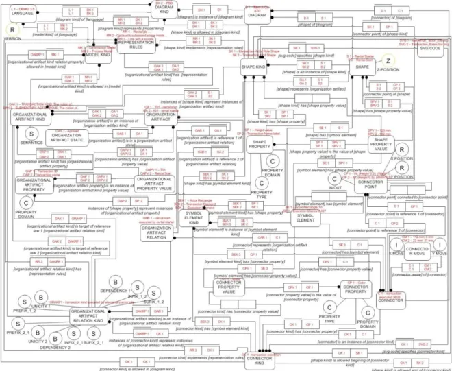
Figure 1 - Simplified version of the UEAOM
This project is based on the adaptation of the UEAOM, which was created during this
project and we can see a simplified version in Figure 1 and further on we have the
complete version in Figure 19, but just using this simplified version it’s possible to
explain the basics of the meta-model editor.
The classes created in UEAOM were created in order to define the specific aspects of
the model and in order to use them, we need to grasp their meaning. For that we need a
brief explanation of the concept behind each class used (examples taken from Figure 4): Language - specifies which type of language is permitted. Each Language can have
multiple Model kinds. Example: «DEMO V3.5»
Model kind - specifies which kind of model is permitted for a specific Language. Each model can have multiple Diagram kinds. Example: «Construction Model
2
Diagram kind - specifies the diagrams of a language, for a specific Model kind. For each Diagram Kind there is a set of Shape Kinds and Connector Kinds that are
allowed to be used in it. The diagrams created are of the schematic kind, and are
used to represent a model, using abstract, graphic symbols. Example: «ATD V3.5». Organizational artifact kind - specifies which kind of Organizational Artifact is
permitted for a specific Model kind and Diagram kind. Example: «ELEMENTARY
ACTOR ROLE V3.5». The OAKs are basic elements that are created for a
determined Model specification like "Elementary Actor Role" or a "Transaction" in
the "Construction Model". OAKs can be represented by instances of Shape Kind.
OAKs may have multiple Organizational Artifact Kinds Element Kinds, such as
"actor name" or "actor id".
Organizational artifact kind relation kind - specifies which kinds of relations are permitted between two Organizational artifact kinds. Example: «TRANSACTION
KIND.executed by.ELEMENTARY ACTOR ROLE V3.5».
Shape kind - specifies the properties values used to create a shape, for a determined diagram kind and version, in conjunction with its SVG code. Shape kinds are the
definition of the OAKs. Example: «ELEMENTARY ACTOR ROLE V3.5 Shape
kind».
Connector kind – specifies the based properties values used to create a connector, for a determined Diagram kind and Version, in conjunction with its SVG code.
Instances of Connector Kinds represent Instances of Organizational Artifact Kind
Relation Kinds, each Connector kind is associated with an OAKRK, and serve as a
connector between OAKs. Example: «EXECUTOR V3.5».
SVG code- specifies the SVG code used for each of the shapes and connectors.
This specification is implemented into a SVG file. Example: «EXECUTOR
V3.5.svg»
Version - specification of the versions associated with each of the previous classes. A Version is needed so each of the classes can be updated. While not displayed in
Figure 1, it`s an intricate part of this project. Example: Two Diagram Kinds can
have the same name but have different versions, so this concept of version is
needed to differentiate them.
For the classes/pages created in the Diagram Editor: Shape, Connector, Diagram,
3
implementation of its associated kind, which is basically an instantiation of their
associated kind, for example, the instantiation of the Connector Kind «EXECUTOR
V3.5», will receive additional information, like the positioning and it`s associations
(diagram, connector kind and Organizational artifact relation), resulting into a
Connector page, and an example of that is the page «Connector 2» which is displayed in
Figure 58.
For most of the implementation of the UEAOM, in order to facilitate the Meta-Editing,
we used templates and forms. Templates are MediaWiki pages created with specific
definition using properties names created in the MediaWiki in order to use the resulting
structure, inside other pages in order to facilitate for an organized page creation and
population of properties for specific pages. These structures contain the name of a
property and the allowed values for those properties, while the type of property
(numeric, page, string) is defined in the property page itself, they can have different
output formats, that is, a different visualization, which normally is in the type of a table
or even plain text.
Forms are basically an interface that allows for the editing and creation of pages, and in
this case permits for the creation and editing of pages with specific templates created for
this project, permitting for the population of property values following a specific set of
rules for each property.
Each of the classes in the Figure 1, represent a template created in MediaWiki, with all
of them having a corresponding Form, that serves to create pages, except for SVG code
class that is the association to the SVG file for the shape kind and connector kind. All of
the classes with “kind” in the name and the Language class are created in the
meta-editor, by using forms to fill the data for each property, except for the connector kind,
which has a different interface (Figure 3), and in the Shape kind template there is a
property that is filled after using the SVG-Edit application (Figure 2), which permits for
the drawing of SVG based images using an web based interface that allows for the
manipulation of the majority of the SVG elements and attributes used in SVG. This
application is modified in order to facilitate for additional properties, and in order to use
4
Figure 2 - SVG-Edit interface
This application creates a SVG file, which will be used in “SVG code” property. This part is explained in the chapter, 4.11.3 SVG-Edit MediaWiki toolbar use procedure.
Figure 3 - Connector Edit interface
For the connector kind, a separate interface called “Connector-Edit”, Figure 3, was
created in order for it to be easier to interact and to permit for the creation of the SVG
5
Organization draWing. This interface permits for the creation of the «Connector kind»
template and respective page, with all the values selected in the interface. It also creates
a SVG file based on the selection of the SVG symbols and line data used, that will be
used in the Diagram Editor, for the icon button and the creating of the connector.
For the rest of the classes, in Figure 1, with a red dot, they are mainly only used by the
Diagram editor created in the parallel project WOW-Wiki aided Organization draWing.
On Figure 4 it’s possible to view an example of some pages created in the Meta-Editor
section of this project, which are displayed in templates, in the form of tables, with a
small explanation of the connections between them, which deepens the ideas behind the
6
Figure 4 – Examples of pages created in the Meta-Editor with their specific interconnections For the Meta-editor section, displayed in Figure 4, we basically used the value of the
principal property of the template and the value of the version used in the page name,
with some divergence between them, better explained in section 4.9. Also it`s possible
to see that most of the values are used in similar properties with the main purpose of
interconnecting the pages and facilitating for a better organization which hopefully
7
In the Meta-editor section, displayed in Figure 4, it`s possible to view an example of
what to expect in the Diagram Editor, which is the use of the page name in the
properties values (the page name «EXECUTOR V3.5», receives, in the property
«Organizational Artifact Kind Relation Kind», the value «TRANSACTION
KIND.executed by.ELEMENTARY ACTOR ROLE V3.5» from the OAKRK page
name.), and also the pages names used have a different structure since they don`t have
the version integrated in the page name, but instead a unique number associated with the
type of page it is, for example, the page name «CONNECTOR 1» is a combination
between the category name and the unique number. This specification is better
explained in section 4.9.
In the next section, the motivation behind this project, the objectives and a synthesis of
the content of each chapter of this dissertation are presented.
1.1
Motivation
A large percentage of IT project as high as 75%, fail to reach the expectations of their
users. One of the main causes behind that failure is the insufficient or inadequate
knowledge of the organizations reality in order for it to be automatized or supported by
information system (IS).The Organizational Engineering[7] discipline emerged in the
90s and applies engineering concepts and methods to organizations in order to finally
understand and represent the multiple facets of an organization, as well as facilitating
the analysis and organizational changes,regardless of the implementation of SIs.
The semantic wikis are easy tools to use, by anyone, regardless of their computer
knowledge. It’s intended that way in order for everyone to contribute for the creation of
a collective consciousness of organizational reality through the use of semantic wikis.
This tool allows for a collective distribution of coherent organizational knowledge in the
form of Semantic elements and relations in models aligned with organizational reality,
that allow for the capture and monitoring of its evolution, as well as developing a more
efficient and effective SIs for supporting such a reality .
By using the Organizational Engineering and Semantic MediaWiki, it should be able to
interconnect the ideas behind Organizational Engineering and a well-established
platform like Semantic MediaWiki to create a coherent Meta-modeling Editor platform
8
1.2
Objectives
The main objective of this project is the analysis and development of a Meta Editor
prototype, based on Semantic MediaWiki that allows for creation and editing of new
types of diagrams, respective symbols and connectors with their respective grammar
and syntactic laws. All of this focused on the DEMO methodology (Design and
Engineering Methodology for Organizations) created and developed by Jan L. G. Dietz
[7] with emphasis in SVG vector graphics.
The main challenges are defining wiki pages and semantic properties using a standard
nomenclature to represent organizational fact types in order to store and connect all
information needed to generate diagrams, the creation and editing of SVG based shapes
using a SVG graphical editor, the use of Semantic Forms extension to manage forms,
which helps to create and edit the semantic properties’ values, and the creation of an
interface for the creation of connectors.
There was another project, which was being created in parallel with this one, that is
essentially the creation of a diagrams editor which uses this current platform (Wiki
Aided Meta Modeling), created in this project, as a database for reading the data for the
shape kinds, connector kinds and a few other specific information needed in order to
create diagrams and will use this platform for saving all the data, using for that, the
existing templates and forms created for that purpose, so it will basically be running in
the background of that diagram editor platform.
The objectives generated from the main objective and challenges were:
Use SVG based images, by that using SVG-edit and it’s extension for MediaWiki.
Adapt the SVG-edit extension with various modifications to its core in order to adapt it to our needs. This adapted extension permitted the creation of shapes
with new SVG attributes created for better organization in the creation of
diagrams for DEMO, which will be later used for background for a SVG
diagram editor.
Create a Connector-Edit interface that will facilitate the creation of connector kinds.
Create the templates and forms that should be used for the creation of the
9
Inter-connect the UEAOM with the templates and properties, by that creating a standard nomenclature.
Create the templates and forms needed for the parallel project WOW-Wiki aided Organization draWing.
If the objectives are achieved, the prototype for a Meta Editor based on the Universal
Enterprise Adaptive Object Model should be working.
1.3
Content
The First section will cover all the related work and the existing problems, the
explanation for some initial choices made, like the type of vectorial graphics used and
why the UEAOM was used.
Next there is the chapter Context, were all the basis notions behind this Meta editor, like
the basic ontological notions, the UNIVERSAL ENTERPRISE ADAPTIVE OBJECT
MODEL (UEAOM) and how it is intended to work, and all notions about enterprise
ontology.
The last section and the most important, the implementation section, explains how the
implementation of UEAOM into MediaWiki was accomplished, by that explaining how
the nomenclature, the properties, templates and forms used, were created, and specially
some of the alterations done to SVG-Edit and the creation of Connector-Edit. Also, in
this section, there’s an explanation on how to use the editor for the creation of all the
pages, and how to create pages with the appropriate template: Language, Model kind,
Diagram kind, organization artifact kind, Shape kind, Connector kind between a few
other that must be created in order for the Meta-editor to work, which is explained in
detail, by giving examples, and information on how to create them and how they are
created inside MediaWiki. This last section will be divided, essentially, in the Semantic
MediaWiki part of the project, the SVG-section and the Connector-Edit section, with
10
2
Related work & problem
2.1
SVG or Canvas Graphical editor type
When deciding on which the graphical editor to choose from, there was two obvious
choices Canvas or SVG, both of them widely used on the Internet.
For the editing of the shapes kinds in the Meta-editor and eventually the Diagram editor
we had to choose between:
SVG, which is the standard for vectorial based graphics.
Canvas, which is an element of HTML5 and is a Pixel based graphics.
Both are the most commonly used on the Internet in terms of image manipulation, in all
sorts of sites, which make them the ideal choices. While initially Canvas happear to be
Vectorial, because it can draw lines and shapes, it isn`t because canvas elements are
bitmaps while the SVG elements maintains vectorial elements, canvas doesn`t. For
example if we draw a shape in a canvas element it will turn into a collection of pixels
while if we draw something into a SVG element it will maintain it`s vectorial identity.
During the research, it was found out that there is a lot of criterion used to compare
SVG to Canvas [3], and a small selection of those criterions are displayed in Table 1
and Figure 5.
Table 1 - Comparison between SVG and Canvas
Criterion SVG Canvas
Line codes Lower number of lines codes in general
Higher number of lines codes in general
Events Can process each event for each sub element separate
Can only process events for the entire screen
Basic forms Rectangle, circle, ellipse, … Only rectangle
Screen size
As the size of the screen get bigger, the rendering time
increases slowly
As the size of the screen get bigger, the rendering time increases
exponentially
Object number
As the amount of objects on screen increases, the rendering
time increases exponentially
As the amount of objects on screen increases, the rendering time
increases slowly Best visualization
format Better scalability Bad scalability
Static images Better because of scalability Degradation because of bad scalability
Pixels manipulation
(visual effects) Worse performance Better performance
Mathematical and animation manipulation
11
Basically canvas is better for complex scenes, real time mathematical animations, video
manipulation and high performance (filters, ray tracers) while SVG is better used for
static Images and high fidelity documents for viewing and printing which is essential to
this project [3].
Figure 5 - Performance Comparison between Canvas and SVG [3]
2.2
Scalable Vector Graphics (SVG)
The SVG, In general, this type of File format support works in the majority of the top
vector graphics editors as both import or export and compared to other vector image
formats, it’s the most well-known and used since it was considered an open standard by
World Wide Web Consortium (W3C) [4], these type of images are saved in XML text
files with the extension .svg and has all the functionalities of the xml and has its own
particular features associated to the drawing of two-dimensional graphics that can
support interactivity and animation with some limitations and in combination with other
technology it can be used to create a graphical editor.
One important fact about SVG is that there are some attributes that can be used inside other attribute like the “style” attribute that can take some attribute like “stroke”, “stroke-width” and few other, while this makes implementing SVG dependent on the way someone wants to code it, the browser can read both ways, which makes SVG
somewhat dynamic in the structuring of the SVG element, so it’s something people
12 2.2.1 SVG graphical editor
After exploring the options and advantages between a SVG graphical editor and a
Canvas graphical editor, the decision was made to go for a SVG graphical editor.
In order to create a graphical editor from scratch or reuse some graphical editor, some
decisions were made; the initial idea of creating graphical editor from scratch would
probably be too time consuming and takes us from the main objective that was to create
a prototype Meta Modeling Editor. So it was necessary to find a compatible SVG
graphical editor and in that search some possibilities where found and by some luck we
found an editor that was already compatible with MediaWiki, but before reaching that
solution there were a few other options viewed.
In the search for web graphical editors, there was an editor that popped out and it was
SVG-edit which is a web-based vector graphics editor that uses only JavaScript,
HTML5, CSS and SVG. This editor is the basis for many projects and by chance there
was already an extension for MediaWiki that used the same editor which is called
Extension: SVG-Edit and provided in-browser creation and editing of uploaded SVG
files in MediaWiki, by using the open-source SVG-edit widget. One of projects
mentioned before was Method Draw which basically uses the SVG-Edit and improves
its overall looks and usability while removing some of the options that were required for
this project.
Some projects that are included in SVG-Edit are JQuery which is a very popular library,
jpicker for fill/stroke picker, jGraduate for picking gradient for the SVG, jQuery UI to
make all the dialog boxes between a few others, all of whom are free and usable by
anyone because of its MIT License (MIT), which means everyone can practically alter
the code as they wish and even sell the result of those alterations if they want to, but a
person needs to mentioned that SVG-Edit was used in that creation.
While it was a strong solution to our problem there was a need to search for additional
possibilities, in that search, it was noticed that there were alot of vector graphics editors,
but most of them, were not web-based.
One of the most used in the web is the Google drawings but it’s not permitted to use any
of its code, so while it’s a very good tool it’s not the best example, to base anything
13
Another SVG editor which can be used online is RichDraw – Simple VML/SVG Editor,
which has some functionalities but it has many issues that a person doesn’t find in the
SVG-Edit.
There were a few projects used to create SVG diagrams, one of those was
Accidentsketch and like the name says, it’s used to draw accidents and helpful to create
SVG for driving test and other car/road related situations, while it wasn’t very helpful,
since it’s a diagram editor and not a SVG editor, it showed some interesting qualities
that helped decide for SVG instead of canvas but not much more than that.
Since there weren’t many online editors, another possibility was found, there are a few
libraries/frameworks related to SVG and one of them was a SVG-to-Canvas library
called Canvg, which is a SVG parser and renderer that helps bypass browsers' inability
to save SVG files and PNGs, by first rendering SVG images in an HTML5 Canvas
element, which was very useful for the Connection-edit part of this project. Another
framework that helps create SVG based applications for the web, was SPARK (SVG
Programmers' Application Resource) which gives an API and conventions for a GUI
component framework built in SVG.
In the end, the SVG-Edit extension for MediaWiki was still the best solution since it
had all the functionalities we needed already, but especially because it was already
integrated with MediaWiki and we could change the code as we wish. This SVG editor
was used for the creation of shape kinds and was initially thought to create connector
kinds but that this idea was left aside since it was easier to create a different type of
interface for that.
2.3
Meta modeling
Meta modeling, in this project, is the analysis, construction and development of a
Meta-editor based on the Universal Enterprise Adaptive Object Model and theories taken
from the same, but before reaching that model, there were some other types of models
to have in consideration, like UML and MOF.
The UML is the standard for creating models but it’s basically software engineering
oriented and doesn’t comply with Meta Models. And because of that, the Meta-Object
Facility (MOF) was invented, which is an Object Management Group (OMG) standard
for model-driven engineering [5], to respond to the need of Meta Modeling architecture
to define the UML. This Meta Modeling architecture is better explained in the context
14
2.4
Meta-Editor
In the initial proposal for this project there was to two platforms, Open Modeling and
Modelworld, to serve as inspiration for the creation of the Meta Editor.
The Modelworld platform does not permit to create new types of models but works
very well for the models that they support and it’s not considered a Meta-editor but a
diagram editor which isn’t what we are looking for but can be helpful for the diagram
editor extension of the Meta-Editor, and it’s the official page is www.modelworld.nl.
The Open modeling platform, which official page is located at
open-modeling.sourceforge.net, is a web-based application for the creation and editing of
architecture models and their structures. It permits for the edit of Meta Models which is
something we have interest in, and it supports the DEMO methodology so with that in
mind and the work done in [8], the general ideas and structure will help for the
definition of the structure of our own framework, since it doesn’t comply with the
semantic way of thinking that this project has in mind and specially with the usage of
the MediaWiki platform. Another important aspect is it’s complex interface which many
will find difficult to use, which is something that we hope that with MediaWiki we will
try to simplify by using forms/templates and properties.
There isn’t any editor that complies with all our needs. To satisfy our dynamic meta-modeling needs, we needed to propose, a new model, that we called Universal
Enterprise Adaptive Object Model (UEAOM). Which was created during this project,
and it serves as a basis for the creation of the Meta Editor in the Semantic MediaWiki
framework.
This conceptual model, UEAOM, allows us to specify the abstract and concrete
syntaxes of any language.
All the process used to create this Meta Editor will be explained in some detail in the
15
3
Context
The basis for this project is the Universal Enterprise Adaptive Object Model [1],
which was being produced during the realization of this project, with several ideas for
the final UEAOM based on the discussions that arose during the project meetings. The
ideas behind UEAOM are explained in the next sections, fully based on [1], [22] and
partially in [10] and [2].
3.1
Enterprise Ontology Theoretical Concepts
3.1.1 Enterprise Ontology
A widely adopted definition of ontology is that ontology is a formal, explicit
specification of a shared conceptualization. It regards the conceptualization of (a part
of) the world, so it is something in our mind. This conceptualization is supposed to be
shared, which is the practical goal of ontologies. This takes also place in
communication. Third, it is explicit. Ontology must be explicit and clear, there should
be no room for misunderstandings. Fourth, it is specified in a formal way. Natural
language is inappropriate for this task, because of its inherent ambiguity and
impreciseness. The notion of ontology as applied in this book is the notion of system
ontology. Our goal is to understand the essence of the construction and operation of
complete systems, more specifically, of enterprises. The goal of enterprise ontologies is
to make available the right amount of the right kind of knowledge of the operation of
the company in a manner that one is able to look through the distracting and confusing
appearance of the enterprise right into its deep kernel. [10]
3.1.2 Factual knowledge
Factual knowledge is the knowledge about the states and state changes of a world. By
factual knowledge we mean knowledge about the state and the state changes of a world,
like knowing that a person or a car or an insurance policy exists, as well as knowing that
the insurance policy of a car started at some date. The basis for understanding factual
knowledge is the meaning triangle, as exhibited in Figure 6 .It explains how people use
signs as representations of objects in order to be able to communicate about these
16
Figure 6 - The meaning triangle
The elementary notions that we will make use of are designated by the words “sign”, “object” and “concept”. The notion of concept is considered to be a subjective notion whereas sign and object are considered to be objective notions. Objective means that it
concerns things outside the human mind and subjective means that it concerns things
that can only exist inside the human mind. The three notions are elaborated below.
A sign is an object that is used as a representation of something else. A well-known
class of signs is the symbolic signs, as used in all natural languages. Examples of
symbolic signs are: the person name "Ludwig Wittgenstein" or the car license number
"16-EX-AF".
An object is an observable and identifiable individual thing, for example a person or a
car. Only concrete objects are observable by human beings. However, there are many
interesting objects that are not observable. The number 3 and the composite object denoted by “Ludwig Wittgenstein owns car 16-EX-AF” are a few of those examples. These objects are called abstract objects.
A concept is a subjective individual thing. It is a thought or mental picture of an object
that a subject may have in his or her mind. An example of a concrete concept is the
mental picture a person has of the person Ludwig Wittgenstein while the example for an
abstract concept is the fact that Ludwig Wittgenstein owns car 1 6-EX-AF.
The basic notions of sign, object and concept are related to each other by three basic
notional relationships:
- Designation - This is a relationship between a sign and a concept. We say that a
sign designates a concept. Example: The name "Ludwig Wittgenstein"
designates a particular concept of the type person.
- Denotation– This is a relationship between a sign and an object. We say that a
sign denotes an object. Examples: the name "Ludwig Wittgenstein" denotes the
17
- Reference is a relationship between a concept and an object, a concept refers to
an object. An example of that is the concept Ludwig Wittgenstein which refers
to a particular person.
The relationships between individual concepts and generic concepts (types), and
consequently between individual objects and classes are depicted in Figure 7 .In this
figure, which is based on Figure 6, the signs (predicate names and proper names) are
deliberately left out because they are not relevant in ontology. Ontology is about the
essence of things, not about how people name them. The resulting figure is called the
ontological parallelogram. It explains how (individual) concepts are created in the
human mind. The notional relationships instantiation, conformity and population are
explained hereafter.
Figure 7 - The ontological parallelogram
Instantiation is a relationship between a concept and a type: every concept is an
instantiation of a type. Examples: the person Ludwig Wittgenstein is an instantiation of
the type person.
Conformity is a relationship between (the 'form' of) an object and a type. We say that
an object conforms to a type. Examples: the object, denoted by the sign "Ludwig
Wittgenstein", conforms to the type person; the object, denoted by the sign "16-EXAF",
conforms to the type car.
Population is a relationship between an object and a class. We say that a class is a
population of objects. A more common way of expressing this is saying that the object
is a member of or belongs to the class. Example: the object, denoted by the sign
"Ludwig Wittgenstein", belongs to the class person.
3.1.3 Stata and Facta
At any moment a world is in a particular state, which is simply defined as a set of
18
state change is called a transition. The occurrence of a transition is called an event.
Consequently, a transition can take place several times during the lifetime of a world,
events however are unique. An event is caused by an act. In order to understand
profoundly what a state of a world is, and what a state transition is, it is necessary to
distinguish between two kinds of objects, which we will call stata (singular: statum) and
facta (singular: factum).
A statum is something that is just the case and that will always be the case; it is
constant. Otherwise said, it is an inherent property of a thing or an inherent relationship
between things. Example: The author of book title T is A. The existence of these objects
is timeless. For example, a particular book title has a particular author. If it is the case at
some point in time, it will forever be the case. A derived statum is defined by its
derivation rule. The being specified of this rule is the only necessary and sufficient
condition for the existence of the derived statum. This marks an important difference
between a world and a database system about that world. E.g. the age of a person in
some world exists at any moment; however, it has to be computed when it is needed.
Stata are subject to existence laws. These laws require or prohibit the coexistence of
stata. For example, if the author of some book is “Ludwig Wittgenstein”, it cannot also be “John Irving”.
Contrary to a statum, a factum is the result or the effect of an act. Example: book title T
has been published. The becoming existent of a factum is a transition. Before the
occurrence of the transition, it did not exist and after the occurrence it does exist. Facta
are subject to occurrence laws. These laws allow or prohibit sequences of transitions.
For example, sometime after the creation of the factum “loan L has been started”, the transition “loan L has been ended” might occur, and in between several other facta may have been created, like “the fine for loan L has been paid”.
3.1.4 World Ontology
“We are now able to provide a precise definition of the ontology of a world; world ontology consists of the specification of the state space and the transition space of that
world. By the state space is understood the set of allowed or lawful states. It is specified
by means of the state base and the existence laws. The state base is the set of statum
types of which instances can exist in a state of the world. The existence laws determine
19
understood the set of allowed or lawful sequences of transitions. It is specified by the
transition base and the occurrence laws. The transition base is the set of factum types of
which instances may occur in the world. Every such instance has a time stamp, which is
the event time. The occurrence laws determine the order in time in which facta are
allowed to occur.” [10]
3.1.5 The Grammar of WOSL
“WOSL is a language for the specification of the ontology of a world. In order to keep the specification of the grammar of WOSL orderly and concise, we present it in a
number of figures, exhibited hereafter. Figure 8 exhibits the ways in which Statum types
can be declared. By the declaration of a Statum type is understood stating that the
Statum type belongs to the state base of the world under consideration. Statum types can
be declared intensionally or extensionally. By intensional we mean the notation of the
statum type as a unary, binary, ternary etc. concept type. Intensional notations are
referred to be a bold small letter (or a string of small letters). Extensional notations are
referred to by a capital letter (or a string of capital letters). To understand what a state of
a world is, it is necessary to distinguish between two kinds of objects: stata and facta.
WOSL language has several graphical pictures to represent these stata and
facta.”[2][10]
Figure 8 - Statum type declarations
Figure 9 and Figure 10 show the specification of existence laws.
20
Figure 10 - Example of a dependency law
Figure 11 shows an example of a factum type.
Figure 11 - Example of a factum type
3.2
Basic Ontological Notions
“The ontological system definition was adopted from [14] which concerns the construction and operation of a system. The corresponding type of model is the
white-box model, which is a direct conceptualization of the ontological system definition
presented next. Something is a system if and only if it has the next properties: (1)
composition: a set of elements of some category (physical, biological, social, chemical
etc.); (2) environment: a set of elements of the same category, where the composition
and the environment are disjoint; (3) structure: a set of influencing bonds among the
elements in the composition and between these and the elements in the environment; (4)
production: the elements in the composition produce services that are delivered to the
elements in the environment. From [14] we find that in the Ψ-theory based DEMO
methodology, four aspect models of the complete ontological model of an organization
are distinguished. The Construction Model (CM) specifies the construction of the
organization: the actor roles in the composition and the environment, as well as the
transaction kinds in which they are involved. The Process Model (PM) specifies the
state space and the transition space of the coordination world. The State Model (SM)
specifies the state space and the transition space of the production world. The Action
Model (AM) consists of the action rules that serve as guidelines for the actor roles in the
21 Figure 12 - The meaning triangle 2
Figure 13 - The ontological parallelogram 2
Figure 14 - The model triangle
Figure 15 - Model triangle applied to
organizations
Figure 16 - Meaning triangle applied to a
transaction OA
Figure 17 - Model triangle applied to the
organization space
“In Figure 12 and Figure 13, we find, respectively, the meaning triangle and the ontological parallelogram, taken from [13] which explain how (individual) concepts are
created in the human mind. We will also base our claims in the model triangle, taken
from [14] and presented in Figure 14. We find that the model triangle coherently
overlaps the meaning triangle. This happens because a set of symbols – like a set of
DEMO representations (signs) that constitute a symbolic system – allows the
interpretation of a set of concepts – like a set of DEMO aspect models, part of the
ontological model, constituting a conceptual system. This conceptual system, in turn, consists in the conceptualization of the “real” inter-subjective organizational self, i.e., the set of OAs constituting the concrete organization system's composition structure and
22
our reasoning. We call the set of all DEMO diagrams, tables and lists used to formulate
the ontological model as ontological representation.
Now relating with the meaning triangle, we can verify that a particular sign (e.g., a
transaction symbol with label membership fee payment), part of an ontological
representation (e.g., actor transaction diagram, representing a library's construction
model) designates (i.e., allows the interpretation or is the formulation) of the respective
concept of the particular transaction part of the respective ontological model (e.g.,
construction model). This subjective concept, in turn, refers to a concrete object of the
shared inter-subjective reality of the organization's human agents (e.g., the particular
OA transaction T02). Figure 16, an adaptation from the meaning triangle depicts this
other reasoning.
Another example of an OA related with T02 would be the transaction initiation OA,
relating T02 with actor role registrar (also designated by A02) and formulated by a line
connecting the transaction and actor role symbols of T02 and A02. Actor role registrar
is, in turn, another OA of the construction space of the library. Once such role is communicated to all employees of a library, it becomes a “living” abstract object part of the shared inter-subjective reality of the library's human agents. Such objects, along
with other OAs of the organizational inter-subjective reality, give human agents a way
to conceptualize their organizational responsibilities – in this case, requesting
membership fee payments to aspirant members. We name this set of all abstract objects
living in the inter-subjective reality of an organization's members as the organizational
self.
From these notions we proposed a set of claims presented in more detail in [10] and
summarized next. An organization – besides producing a set of products or services for
its environment – also produces itself. That is, enclosed in its day-to-day operation,
there will be parts of its operation which change the organization system itself, i.e.,
change the set of OAs that constitute its composition, structure and production. By
formally and explicitly specifying these change acts one keeps a definite and updated
record of produced OAs. Such a record – the OAs base – constitutes the means for one
to always be able to conceptualize the most current and updated ontological model of
the organizational self. Thus the continuous production of the organizational self should include the synchronized production of the collective and subjective “picture” (awareness) of the organizational self – the conceptualization that constitutes its
23
system – an ontological representation that allows the interpretation of the ontological
model and the conceptualization (awareness) of the organizational self. To separate
concerns, we propose that change acts are performed by a (sub-)organization considered
to exist in every organization (O) that we call: G.O.D. Organization (GO) – change acts
lead to the Generation, Operationalization and Discontinuation of OAs. The GO's
production world will contain the current state of O's self as well as its relevant state
change history. The GO has the role of continuously realizing and capturing changes of
organizational reality. Thus, by implementing the GO pattern in a real organization, in
an appropriate manner, providing automatic generation of ontological representations
derived from the OAs base, one can achieve OSA. This is possible because one can
implement clear rules that, based on the arrangement of OAs of the organizational self,
automatically produce the appropriate ontological representation which, in turn, allows
the appropriate interpretation of the ontological model, that is, the correct
conceptualization of the organizational self.
OAs constituting the organizational self are arranged in a certain manner as to specify
all the spaces (state, process, action and structure) of an organization's world, i.e., they
have to obey certain rules of arrangement between them. We call the specification of
these rules as the ontological Meta model. The ontological meta-model is the
conceptualization of the OA space. By OA space we understand the set of allowed OAs.
It is specified by the OA base and OA laws. The OA base is the set of OA kinds of
which instances, called OAs, may occur in the state base of the GO's world. The OA
laws determine the inclusion or exclusion of the coexistence of OAs. The definition of
the OA space is quite similar to the definition of state space of an organization's
production world – specified in World Ontology Specification Language (WOSL) [13] – and, thus, it is appropriate to use WOSL to express the ontological meta-model in, what we propose to call: the Organization Space Diagram (OSD). DEMO's OSD is
currently called as the DEMO Meta Model (DMM), the chosen name for the
specification provided in [14] and consisting, in practice, in the OSDs corresponding to
the four DEMO aspect models: SM, CM, PM and AM. These diagrams formulate, for
each aspect model, the OA kinds out of which instances – OAs – can occur in the
organizational self and coexistence rules governing how to arrange these instances.
Another reason we propose to use the expression Organization Space Diagram is
because we're in fact looking at a Space Diagram which, following the model triangle
24
ontological meta model. So, for coherency reasons, one should not use terms “Meta” and “Model” to name those figures but use, instead, the term Organization Space Diagram. The OSD allows the interpretation, in one's mind, of the ontological meta
model. The complete set of organization artifact kinds and laws governing the
arrangement of their instances constitutes the organization space. The conceptualization
of the organization space consists in the ontological meta-model which, in turn, is
formulated in what we call the Organization Space Diagram. A depiction of this
reasoning is present in Figure 17, another adaptation from the model triangle. The
G.O.D. organization is addressed in detail in [1]. This is an evolution of the conceptual
model proposed in other works, taking in account state-of-the-art related model theory
and concepts described next.” [1]
3.3
Theoretical Foundations on Models
“In a graphical modeling language, the vocabulary is expressed in terms of pictorial signs. Those graphical primitives form the concrete syntax i.e the lexical layer of such
language. The abstract syntax, on the other hand, is usually defined in terms of an
abstract visual graph or a meta-model specification. A meta-model specification of a
language defines the set of grammatically correct models that can be constructed using
that language, a vocabulary. The concrete syntax provides a concrete representational
system for expressing the elements of that meta-model [19]. In a communication
process, besides agreeing on a common vocabulary, the participants need to also share
the meaning for the syntactical constructs being communicated so they are able to
interpret in a compatible manner the expressions being used. To this end a language's
semantics can be constructed in two parts: a semantic domain i.e. the real world entities
to which those semantics apply and a semantic mapping from the syntactic vocabulary
to such domain that tells us the meaning of each of the language's expressions as an
element in that specific domain. In graphical languages, vocabulary, syntax and
semantics cannot be clearly separable. A graphical vocabulary of a modeling language
may include shapes of differing sizes and colors that often fall into a hierarchical typing
that constrains the syntax and informs about the semantics of the system [19]. The
abstract syntax of a model manages the formal structure of the model elements and the
relationships amongst them [21].
The MetaObject Facility (MOF) Specification is the industry-standard environment
25
across a network, stored in a repository and then retrieved, rendered into different
formats like XMI or XML, transformed, and used to generate application code [5]. The
Adaptive Object Model (AOM) is a pattern that represents classes, attributes, and
relationships as meta-data. It is a model based on instances rather than classes. Users
change the meta-data (object model) to reflect changes in the domain. These changes modify the system’s behavior. In other words, it stores its Object-Model in a database and interprets it. Consequently, the object model is active, when you change it; the
system changes immediately [15].” [1]
3.4
The universal enterprise adaptive object model
Figure 18 - Type Square
“The long term objective of our research is the development of a wiki-based system that allows an effective integrated enterprise modeling, while allowing dynamic evolution of
meta-models, models and their representations, while providing intuitive navigation
through their elements and also their semantics, allowing wide-spread model
interpretation and distributed model creation and change, reflecting enterprise changes,
thus addressing our problem. An essential step in this direction is what we call the
Universal Enterprise Adaptive Object Model (UEAOM), depicted in Figure 19. We
apply the AOM pattern referred in the previous section so that each page or semantic
property of our semantic wiki-based system corresponds to instances of classes of our
AOM.
Wiki pages, that are instances of class DIAGRAM, automatically generate SVG
diagrams based on shape and connector pages. These pages also allow dynamic editing
of diagrams and underlying models. We also apply the type-square pattern [15] –
depicted in Figure 18– 4 times as to allow run-time dynamic change of: (1) meta-model
elements, (2) model elements, (3) shape elements and (4) connector elements. Our
UEAOM is represented with the World Ontology Specification Language (WOSL)[13].
26
the specification of the anatomy of Archimate [20], a similar effort to ours. In [18] a
relation between Adaptive Object Model pattern and the MOF standard is presented,
where run-time instances of the operational level are equivalent to MOF's M0 and
knowledge level; classes, attributes, relations and behavior is equivalent to M1, being
M2 an equivalent to the models used to define an AOM. As in the work of Ferreira et
al., in our UEAOM all these MOF levels are projected as run-time instances. In our
prototype system, we have as instances both organization artifacts – i.e., concrete
organization models – and organization artifact kinds – i.e., the meta-model
specification or, in other words, the abstract syntax. So both M1 and M2 levels of the
MOF framework exist and change at run-time. But the MOF and Ferreira's initiative are
too software development oriented and too complex for our needs. The main idea is to
apply these fundamental theoretical foundations and adapt them to the field of enterprise
ontology.
Having the UEAOM contextualized, an explanation of its content is now due. With the
UEAOM's classes we are not explicitly specifying syntaxes of particular modeling
languages. What we can do, while instantiating these classes, is to specify any syntax of
any modeling language, along with particular models of each language, and also their
evolution, all this in run-time. For a better understanding and following the essential and
important validation by instantiation principle [17] we present, for all elements of our
AOM, example instances for the DEMO language, namely a fragment of the EU-rent
case's Construction Model and its respective Actor Transaction Diagram. Thus, we can
find, in red color expressions, instances of both our classes and fact types of our
UEAOM concerning the EU-rent case which allow a better interpretation of our
proposal.” [1]
3.4.1 Abstract Syntax
“Relevant classes for the specification of the abstract syntax of any version of any language are presented in Figure 20. The main concepts of the abstract syntax
specification are expressed in the classes LANGUAGE, MODEL KIND,
ORGANIZATIONAL ARTIFACT KIND (OAK) and ORGANIZATIONAL
ARTIFACT RELATION KIND (OARK). They specify all allowed artifacts (e.g.
transaction kind OAK and transaction execution relation OARK) for different types of
models that can exist for different languages. Class ORGANIZATIONAL ARTIFACT
27
each group specifies one of the two sides of an allowed relation between two OAKs.
The ones named prefix, infix and suffix specify the formulation that can be done around
the names of the two OAKs being related. Most times, only the infix needs to be
specified. With the unicity and dependency properties we specify the cardinality of the
relation and which OAKs are mandatory or not to participate in the relation. Reference
law fact types specify which two OAKs are allowed to participate in this relation.
Practical example of the first set of the referred 5 properties: F Transaction Kind T is
initiated by Elementary Actor Role corresponds to a set of Dependency 1, Reference
law 1, Unicitiy 1, Infix_1_2 and Reference law 2. F Elementary Actor Role T is initiator
of Transaction Kind would be its corresponding Dependency 2, Reference law 2,
Unicitiy 2, Infix_2_1 and Reference law 1. Thanks to this part of our UEAOM
specification we allow a precise and formal formulation of the abstract syntax of
models, already giving considerable semantics thanks to the prefix, infix, suffix and
OAK names that can be composed in formulations for each direction of the relation.
Instances of class ORGANIZATION ARTIFACT PROPERTY specify intrinsic
properties of OAKs, like identifiers and names. The respective property PROPERTY
DOMAIN allows us to specify the domain for each intrinsic property of an OAK (e.g.,
string, number, etc.). Examples of instances are property transaction id with domain
28
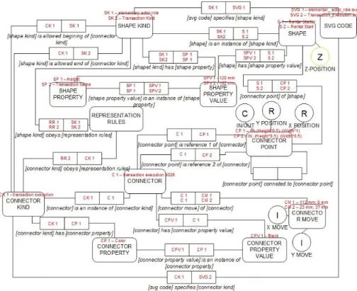
Figure 19 - Universal Enterprise Adaptive Object Model
“In Figure 21we can see an excerpt of the current DEMO ontological meta-model and the UEAOM classes used to define it. Both these models are the equivalent to the M2
MOF model that, as we have seen, sets the rules for specifying concrete models. All
elements of this meta-model can be considered instances of the classes we just have
presented. The binary fact type [elementary actor role] is an initiator of [transaction
kind] is, in our UEAOM, an instance of ORGANIZATIONAL ARTIFACT
RELATION KIND class, with values for the infixes being: initiates and initiated by.
There are, however, other classes: DIAGRAM KIND, SHAPE KIND, CONNECTOR
KIND, CONNECTOR and SHAPE PROPERTY that are present in this Figure 21 and
are part of the meta-model level of the UEAOM but are not part of the abstract syntax,
29
Figure 20 - UEAOM - Abstract Syntax classes


![Figure 5 - Performance Comparison between Canvas and SVG [3]](https://thumb-eu.123doks.com/thumbv2/123dok_br/15660983.622180/22.892.182.713.290.570/figure-performance-comparison-canvas-svg.webp)