Cavity preparation machine for the
standardization of
in vitro
preparations
Abstract: Several in vitro studies employ the confection of cavity prepa-rations that are dificult to standardize by means of manual high speed handpieces. This study presents the development of a cavity preparation machine designed to standardize in vitro cavity preparations. A metal base of 25 mm x 25 mm x 4 mm (length x width x height) was coupled to a small mobile table which was designed to be able to move by means of two precision micrometers (0.01-mm accuracy) in the horizontal direc-tions (right-left, and back-front). A high speed handpiece was coupled to a metallic connecting rod which had an accurate dial indicator enabling control of the vertical movement. The high speed handpiece is also able to move 180° around its longitudinal axis and 360° around its transver-sal axis. The suggested cavity preparation machine precisely helps in the standardization of cavity preparations for in vitro studies.
Descriptors: Dental cavity preparation; Laboratory techniques and procedures; Laboratory equipment.
Carlos José Soares(a)
Rodrigo Borges Fonseca(a)
Henner Alberto Gomide(b)
Lourenço Correr-Sobrinho(c)
(a) Professors, Operative Dentistry and Dental
Materials Department, Dental School, Federal University of Uberlândia.
(b) Full Professor, Department of Mechanical
Engineering, Biomechanics Group, Mechanical Engineering School, Federal University of Uberlândia.
(c) Professor, Department of Dental Materials,
Piracicaba Dental School, State University of Campinas.
Corresponding author:
Carlos José Soares Faculdade de Odontologia Universidade Federal de Uberlândia Av. Pará, n. 1720
Uberlândia - MG - Brazil CEP: 38400-902
E-mail: carlosjsoares@umuarama.ufu.br
Introduction
In vitro tests, within their limits, provide some idea of the behavior of restorations in simulated clinical situations.1 Thus, it seems important to
de-termine the forces that may induce fracture of such restorations and suggest a preparation that will pro-vide greatest resistance to fracture or better marginal accuracy.2-5 Several studies have assessed the
inlu-ence of cavity preparation designs on fracture resis-tance of restored teeth,2,4-9 degree of polymerization
of composite resin and resin cements, marginal and intaglio adaptation of indirect restorations,4,5,10,11
ad-hesive bond strength of restorations,12 transference
of stresses to tooth structure,13,14 cuspal delection
and microleakage.15 Some of these studies have
em-ployed manual preparation of the cavities with high speed handpieces8,16,17 but in some instances it is not
mentioned how were the cavity dimensions standard-ized,18 although the non-standardization could affect
the reliability of the results. Etemadi et al.18 (1999)
assessed the reproducibility of a previous established tooth preparation design for posterior resin-bonded porcelain restorations, which should be manually re-produced by specialists, and found a great difference in the preparations made by different individuals.
According to the degree of accuracy, the meth-od of standardization may use scaled perimeth-odontal probes,19 analogical calipers,15,20 digital calipers,21
measuring microscopes,22 precision electronic
mi-crometers,19,23 handpieces mounted on dental
sur-veyors24 and cavity preparation machines equipped
with precision micrometers.13,14 The most inaccurate
methods employ manual measurement of cavities after or during preparation, while the most accurate ones use instant digital measurement during prepa-ration. According to Sá, Gabrielli25 (1987), the irst
cavity preparation machine for in vitro studies was created by the same authors in 1975. They used an optical microscope with some adaptations for at-taching a high speed hand piece and the sample to be prepared. It seems of great importance to search for a way to standardize cavity preparations, espe-cially for in vitro tests. Although several studies have used cavity preparation machines or other types of devices, none of them describe how they work, nor do they present the mechanical instruments used for
their construction. The aim of this study was to sug-gest a cavity preparation machine designed to stan-dardize in vitro cavity preparations.
Material and Methods
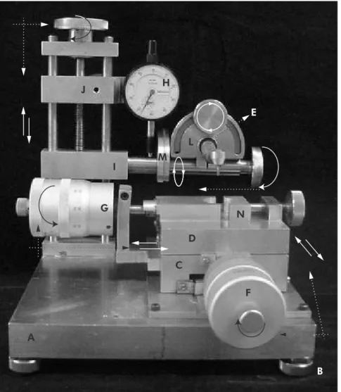
Cavity preparation machine description The cavity preparation machine, as demonstrated in Figure 1, was developed at the Dental, and Me-chanical Engineering Schools, Federal University of Uberlândia, MG, Brazil. The principal components of the entire device are two precision mechanical micrometers and one dial indicator with a 0.01 mm accuracy (Mitutoyo Am. Corp., Ontario, Canada), one high-speed hand piece (Kavo, Joinville, SC, Brazil), a stainless steel base (25.0 mm x 25.0 mm x 4.0 mm - length x width x height) with four ad-justable support feet, a ixed stainless steel table (10.0 mm x 10.0 mm x 5.0 mm – length x width x height), a mobile table which is coupled to two pre-cision micrometers and a metal holder to keep the prepared tooth steady.
It is necessary to use a stainless steel base with at least 4 mm in height in order to enable the attach-ment of the other components (Figure 1A). More than 4 mm is not necessary and will make it too heavy. Also, 25.0 mm x 25.0 mm (length x width) seems important to offer enough stability to the ma-chine when it is working. Four adjustable feet (Fig-ure 1B) were added to this base in order to allow correct adaptation to the surface where the machine is placed. These feet are connected to the base by means of threads and when they are screwed they adapt to the surface. Irrespective of this possibility it is advisable to use the machine over a plane and lat surface to avoid any risk of visual imperfections due to inclination. The next step is to attach a ixed ta-ble (Figure 1C) with 10.0 mm x 10.0 mm x 5.0 mm (length x width x height) to this metallic base. This table is a support to the mobile table and it has a lateral perforation which enables a connection with the irst micrometer (Figure 1F).
20.0 mm-high screw which goes through two other horizontal connecting rods (Figure 1I;J). The cen-tral perforation of the superior horizontal connect-ing rod (Figure 1J) should be large enough to permit free passage of the screw. On the other hand, the in-ferior horizontal connecting rod (Figure 1I) should have a threaded central perforation which will en-able upward and downward controlled movements when the screw is screwed. On the back of the su-perior connecting rod there is a screw designed to hold it in position when there is any movement on the inferior connecting rod. This is necessary be-cause one micrometer (Figure 1H) is attached to the superior connecting rod and it will be responsible for showing how many millimeters the inferior con-necting rod is moving upward or downward. This micrometer has a metallic spring which contacts
the inferior connecting rod; when there is any verti-cal movement the spring is stretched or compressed and registers movement in micrometers. Figure 2 shows the inferior horizontal connecting rod mov-ing 2.5 mm downward; as it moves downward less load is applied to the micrometer spring and then it registers the extension of the movement.
A high speed handpiece (HS) is attached to the inferior horizontal connecting rod, which controls its vertical movement, as described before. The HS has a rigid attachment (Figure 1E) to a metal device (Figure 1L) that allows it to move 180° around its longitudinal axis and 360° around its transversal axis. In order to establish standardized points where one could check the correct position of the HS, sur-face marks were drawn on the metal devices (Fig-ure 1L;M).
H
L M
D
C
F N G
A
I J
E
B
A mobile table (Figure 1D), placed above the ixed table (Figure 1C), should be connected to two micrometers (Figure 1G;F) enabling horizon-tal movements from right to left, left to right, back to front, and front to back (see Figure 1). A metal holder (Figure 1N) on the mobile table maintains the tooth to be prepared in a steady condition. Orig-inally, teeth must be embedded in resin cylinders to enable correct adaptation to the holder.
Results
As a result of the use of the suggested machine, an example of its use is shown right below.
Example of use of the machine
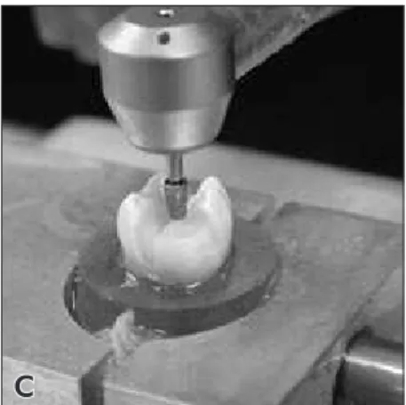
Figure 3 shows the confection of an onlay prepa-ration with mesio-buccal cusp coverage. One freshly extracted human irst mandibular molar was se-lected. The tooth was collected after the patient had signed an informed consent, in accordance with the ethics committee, Federal University of Uberlândia, MG, Brazil (protocol #029/2003). In this example we used a tapered round-ended diamond bur which has 4.0 mm in length and 1.5 mm/2.5 mm in mini-mum/maximum diameter (#3131 diamond bur, KG Sorensen, Barueri, SP, Brazil). First of all, the dia-mond bur was attached to the HS and it was posi-tioned at the center of the tooth’s occlusal surface (Figure 2). This position needs to be recorded on the
micrometer H (Figure 1H) since it will be an initial parameter of how deep the occlusal isthmus will be. The position of the micrometer was recorded and the inferior connecting rod with the HS was positioned 2.5 mm above the center of the occlusal surface (Figure 2). By rolling the micrometer (Figure 1F) the HS runs from front to back (Figure 3A) and deines a 2.5 mm-wide and 2.5 mm-deep occlusal isthmus (Figure 3A;3B). Mesial and distal boxes were created 1.5 mm above the pulpal wall, and with a 1.5 mm-deep gingival wall.
The process of cuspal coverage can be easily done by cuspal reduction following the deinition of the desirable inishing line. Cuspal reduction starts by positioning the diamond bur at the top of the cusp to be prepared and recording on micrometer H this position. The HS connecting rod is then lowered in accordance to the amount of cusp reduction that is needed. In this case, the mesio-buccal cusp was reduced by 2.0 mm (Figure 3B;3C). To complete cuspal coverage, a 1.5 mm-thick chamfer inishing line was created 1.5 mm below cusp reduction (Fig-ure 3D). The prepared tooth is shown in Fig(Fig-ure 3E.
Possible modifications
In spite of the fact that the present cavity prepa-ration machine enables almost all sorts of prepara-tions, some especial modiications can be performed in order to make it easier to work or more adequate
B A
for a speciic situation. It is possible to replace the mechanical micrometers by digital ones, which would facilitate the visualization of the quantity of movement of the mobile table. Also, replacement of the HS by a low speed one is possible, if desirable.
Discussion
When studying any variable within a research it is mandatory to search for standardization tech-niques in order to better answer the tested hypoth-esis and even more to enable more power to any conclusion. Thus, standardization of preparations, techniques and materials play an important role in the impact of research. The coniguration of a cavity preparation has been of great interest to experimen-tal and mathematical studies. Finite element analysis is a mathematical approach which can be especially indicated to study stress distribution on teeth with various preparation designs.12 When the same
prep-arations are to be reproduced for an in vitro test it is thus extremely necessary to search for a method in
which the same preparations could be confectioned in different samples. The use of a cavity preparation machine, as shown in this study, seems to be the most reliable method. Shirai et al.12 (2005) studied
the effect of cavity coniguration on bonding effec-tiveness, showing that polymerization contraction stresses can negatively affect adhesion in a high C-factor Class I cavity, for some adhesive systems. This study employed a high-speed hand piece with a cylindrical diamond bur mounted on a MicroSpeci-men Former (University of Iowa, Iowa City, IA, USA) in order to create a standard box-type Class-I cavity (4.5 x 4.5 mm²). Thus, the cavities should be uniform within the groups, and certainly this goal was achieved by employing the MicroSpecimen For-mer, a type of cavity preparation machine.
Even with the use of a method to measure the size of cavity preparations some studies employ manually prepared cavities22 and certainly the
similarity between samples is compromised. Ide-ally, standardization of preparations should be per-A
D E
B C
formed in the same device which prepares the teeth because it is possible to have instant measurement. In spite of the fact that there are studies which em-ploy extremely accurate devices to measure prepara-tions (0.002 mm-accuracy by Potiket et al.22, 2004),
when measurement is performed after preparation there is a chance that it will be necessary to repeat the preparation in a new sample if tooth structure removal was excessive.
Several factors may be considered before using a cavity preparation machine. In some instances, the selection of teeth with similar size, shape and volume may possibly be the most important one. Also, pre-deinition of the preparation design to be used is mandatory because it will inluence the re-quired handling characteristics of the machine and the shape of the diamond or carbide burs. In order to facilitate preparations, speciic diamond/carbide burs can be newly designed, as done in this study. In the example shown in Figure 3, the #3131 diamond bur could easily perform the expected cavity prepa-ration. Thus, the researcher should correctly estab-lish the preparation design to be performed and, af-ter that, search for the speciic bur which would be most indicated for it. The diamond bur used in this study allows the confection of every type of inlay and onlay preparations. Veneer and crown prepara-tions certainly will require other types of burs.
When dealing with complex cavity prepara-tions, inlay and onlay preparaprepara-tions, one of the dis-advantages of the machine is that it is not possible to ensure that all internal angles will get rounded (Figure 3E), so after preparation the tooth
prepara-tion angles will need to be manually rounded. This fact can induce variations in preparations but the use of low grit diamond burs in low speed can avoid signiicant alterations. Some preparation machines seem to be able to be mechanically handled instead of manually handled, as the one of this study. This is certainly an interesting characteristic, but manu-al handling enables control of tooth wear and this characteristic can possibly be mandatory when simulating cavity preparations for indirect restora-tions. The type of cavity preparation machine will be guided by both the type of study and related vari-ables. Several studies were accomplished with the use of this machine24,26-28 and it is the opinion of all
authors that its use was mandatory for the correct standardization of preparations. Furthermore, in order to avoid bias and methodological errors and in the search for more accurate results, a prepara-tion machine should be employed.
Conclusion
The suggested cavity preparation machine pre-cisely helps in the standardization of cavity prepara-tions for in vitro studies. It is recommended that the machine be used in order to avoid incorrect inter-pretation of the results.
Acknowledgments
This study was supported by CNPq (Grant #1991/157) and FAPEMIG (Grant #154/05). This manuscript is free of conlict of interest and the au-thors have no inancial interest in any of the men-tioned companies or products.
References
1. Ku CW, Park SW, Yang HS. Comparison of the fracture strengths of metal-ceramic crowns and three ceromer crowns. J Prosthet Dent. 2002;88(2):170-5.
2. Burke FJ. Fracture resistance of teeth restored with dentin-bonded crowns: the effect of increased tooth preparation. Quintessence Int. 1996;27(2):115-21.
3. Burke FJ, Watts DC. Fracture resistance of teeth restored with dentin-bonded crowns. Quintessence Int. 1994;25(5):335-40. 4. Cho L, Choi J, Yi YJ, Park CJ. Effect of finish line variants on
marginal accuracy and fracture strength of ceramic optimized
polymer/fiber-reinforced composite crowns. J Prosthet Dent. 2004;91(6):554-60.
5. Cho L, Song H, Koak J, Heo S. Marginal accuracy and frac-ture strength of ceromer/fiber-reinforced composite crowns: effect of variations in preparation design. J Prosthet Dent. 2002;88(4):388-95.
7. Eakle WS, Braly BV. Fracture resistance of human teeth with mesial-occlusal-distal cavities prepared with sharp and round internal line forms. J Prosthet Dent. 1985;53(5):646-9. 8. Krejci I, Duc O, Dietschi D, de Campos E. Marginal
adapta-tion, retention and fracture resistance of adhesive composite restorations on devital teeth with and without posts. Oper Dent. 2003;28(2):127-35.
9. Mondelli J, Steagall L, Ishikiriama A, de Lima Navarro MF, Soares FB. Fracture strength of human teeth with cavity preparations. J Prosthet Dent. 1980;43(4):419-22.
10. Jahangiri L, Wahlers C, Hittelman E, Matheson P. Assess-ment of sensitivity and specificity of clinical evaluation of cast restoration marginal accuracy compared to stereomicroscopy. J Prosthet Dent. 2005;93(2):138-42.
11. Sjogren G. Marginal and internal fit of four different types of ceramic inlays after luting. An in vitro study. Acta Odontol Scand. 1995;53(1):24-8.
12. Shirai K, De Munck J, Yoshida Y, Inoue S, Lambrechts P, Suzuki K et al. Effect of cavity configuration and aging on the bonding effectiveness of six adhesives to dentin. Dent Mater. 2005;21(2):110-24.
13. de Vree JH, Peters MC, Plasschaert AJ. The influence of modi-fication of cavity design on distribution of stresses in a restored molar. J Dent Res. 1984;63(10):1217-20.
14. Magne P, Perakis N, Belser UC, Krejci I. Stress distribution of inlay-anchored adhesive fixed partial dentures: a finite element analysis of the influence of restorative materials and abutment preparation design. J Prosthet Dent. 2002;87(5):516-27. 15. Palin WM, Fleming GJ, Nathwani H, Burke FJ, Randall RC.
In vitro cuspal deflection and microleakage of maxillary pre-molars restored with novel low-shrink dental composites. Dent Mater. 2005;21(4):324-35.
16. Belli S, Erdemir A, Ozcopur M, Eskitascioglu G. The effect of fibre insertion on fracture resistance of root filled molar teeth with MOD preparations restored with composite. Int Endod J. 2005;38(2):73-80.
17. St-Georges AJ, Sturdevant JR, Swift EJ Jr, Thompson JY. Fracture resistance of prepared teeth restored with bonded inlay restorations. J Prosthet Dent. 2003;89(6):551-7.
18. Etemadi S, Smales RJ, Drummond PW, Goodhart JR. Assess-ment of tooth preparation designs for posterior resin-bonded porcelain restorations. J Oral Rehabil. 1999;26(9):691-7. 19. Rasheed AA. Effect of bonding amalgam on the reinforcement
of teeth. J Prosthet Dent. 2005;93(1):51-5.
20. Ortega VL, Pegoraro LF, Conti PC, do Valle AL, Bonfante G. Evaluation of fracture resistance of endodontically treated maxillary premolars, restored with ceromer or heat-pressed ceramic inlays and fixed with dual-resin cements. J Oral Re-habil. 2004;31(4):393-7.
21. Zhi-Yue L, Yu-Xing Z. Effects of post-core design and ferrule on fracture resistance of endodontically treated maxillary central incisors. J Prosthet Dent. 2003;89(4):368-73. 22. Potiket N, Chiche G, Finger IM. In vitro fracture strength
of teeth restored with different all-ceramic crown systems. J Prosthet Dent. 2004;92(5):491-5.
23. Ozturk AN, Belli S, Eskitascioglu G. The in vitro effect of pulpal pressure and luting agent on tensile bond strength of complete cast crowns. J Prosthet Dent. 2004;91(3):253-7. 24. Soares CJ, Martins LR, Fernandes Neto AJ, Giannini M.
Marginal adaptation of indirect composites and ceramic inlay systems. Oper Dent. 2003;28(6):689-94.
25. Sá D, Gabrielli F. Estudo da microinfiltração marginal em res-taurações com amálgama. Efeito de liga, verniz e brunidura. Rev Fac Farm Odontol Ribeirão Preto. 1987;16:22-7. 26. Soares CJ, da Silva NR, Fonseca RB. Influence of the
feld-spathic ceramic thickness and shade on the microhardness of dual resin cement. Oper Dent. 2006;31(3):384-9.
27. Soares CJ, Martins LR, Fonseca RB, Correr-Sobrinho L, Fernandes Neto AJ. Influence of cavity preparation design on fracture resistance of posterior Leucite-reinforced ceramic restorations. J Prosthet Dent. 2006;95(6):421-9.