Vol-7, Special Issue-Number5-July, 2016, pp983-987 http://www.bipublication.com
Research Article
Passive Radar based on IFM(Design and Analysis Algorithm
for Location Finder)
Darab Heirani and MohammadrezaGhajar
Enghelāb-e Eslāmi Technical College, Technical and Vocational University
Tehran, Iran.
ABSTRACT
Nowadays the necessity of continuous development of defense industries is inevitable for any state. The most important defense factors include the detection of airspace intruder within a country. Thus, radars have got high significance. The purpose of the paper is to design and analyze Monostatic passive radar theory acting in L frequency band whose aim is the positioning of an object in vacuum. The radar is designed based on the application of eight instantaneous frequency measurement receivers and synchronic checking of amplitude and signal phase in all receivers and also the computation of instantaneous power and the comparison of the powers in the receivers. Simulations show that the radar in system coordinate center, which is defined as default, has got a high accuracy and approaching to edges makes it decreased.
Key words:-Instantaneous frequency measurement, Passive radar,L frequency band,Monostaticradar ,Nonlinear equations systems
1. INTRODUCTION
With the extension of scope and type of threats, the necessity of designing and application of radar systems commensurate with threats posed have raised. Active radars with high wave-length due to their high power readily are identified by positioning systems. In addition, the radars are threatened by anti-radiation missiles [1].
In fact, the disadvantages of active radar, clarify the advantages of passive radars. This type of radar does not have any specific transmitter and employ environmental signals as transmitted signals. Thus, it has some advantages in this regard, for example it is small and portable, has lower manufacturing cost, and does not need any specific frequency band. Due to not having any dedicated transmitter, the disadvantage of the radar is that transmitted waveform in term of type and power is not controllable and thus,
manufacturing technology is so complicated [2,3]. The fine frequency estimation of received signal is very important in Electronic Warfare and communication systems. The performance of radar classification depends on the accuracy of frequency measurements [4].
Instantaneous Frequency Measurement (IFM) is important for modern radar warning receivers, providing initial threat classification of incoming signals and suggesting frequency ranges to focus processing resources [5].
2. DESCRIPTION
In the paper, according to (Fig1), we will design a Monostatic radar using eight IFM receivers. IFM receivers are located in eight different situations. In this regard, IFM1, IFM3, IFM5, IFM7 receivers present the measurements along X and Z axes and IFM2, IFM4, IFM6, IFM8 provide the measurements along with Y and Z axes. Now, if we have an algorithm that compute and compare this distances, we can acclaim that we have got the aimed target 3D coordinates.
2.1 Identifying problem assumptions
Before introducing an algorithm, we have to address an important point that is all calculations are done in a unit time (t0) for all receivers. In the time, eight IFM must report a frequency band to make sure which is a specified target in the tracking range and the received signal is not false alarm or target waves out of the tracking range. Since IFM specifies the intermediate frequency, the process is done easily. It is worth noting that target was facing by receivers. on the other hand, gain in all receivers are into the target and the receivers are omnidirectional and radar acts in L frequency band and ideal conditions are considered.
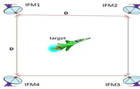
Now considering the assumptions, we begin designing and analyzing the Monostatic passive radar. According to (Fig2), the distance between IFMs is D. The target coordinates is calculated as follows.
2.2 Algorithm Design
According to (Fig3), suppose that the aimed target is located in the tracking range. According to unambigious range equation of an object in vacuum, the relation between transmitted power and IFM output power is declared as
wherePt is transmitted power by the target to be tracked, Pr is output power IFM (received power) and R is radiation radius (Target to each IFM). According to (1) we have
Having got “Ri”s and according to fixed distance of receivers, the target coordinates is specified as follows.
Ri calculated strategy to define it; Because Pt source unit, so the value of all the receivers equal and the other hand 4π is a constant factor, so the following equation can be fulfilled according to Pt.Therefore, (1) can be written as
According to (Fig3), suppose the target is in a quadrant of coordinate system. Plotting a line between the target and receivers, tow right triangles are formed in which, the hypotenuse is equal to Ri
2
in (2). In addition, the values of “Pri” are proposed by IFMs. So, we can say that “Ri”s
are multiplies of each other.
Now using geometric rules, we write governing relations between the two right triangles based on R12 and R32 and thus obtain a non-linear three unknowns equation which is called P1(X,Y,Z). By the same reasoning, we write the relationship between R22 and R42 and obtain another nonlinear three unknowns equation named P2(X,Y,Z). The approach is investigated for the correspondence between the other two receivers and finally we obtain a system of four equations with three unknowns as follows
And D is the distance between receivers and the X, Y, Z are target coordinates.
The system of equations of (4) to (7) is the algorithm we aimed to obtain. Now, according to obtained relations, an algorithm is presented in form of diagram blocks in (Fig4).
In (Fig4)algorithm, inputs are the received powers derived from IFMs and D rate. D is defined by user and equations (4) to (7) are nonlinear and must be solved by numerical methods. A proposal in this field, using MATLAB software package and take advantage of this software is command “fsolve”. The reason for this suggestion is that the software can be the receiver information generated by the ADC circuits and to easily call and put this information into the algorithm in (Fig4)and detected position of the target.
3. RESULTS 3.1 Simulation
After designing intended radar algorithm, we want to simulate it. In order to do this we simulate a path as the path of the target. Then we trace the path according to the results.
(Fig5)shows two sample plans that are designed according to this plan. According to what we said eight IFMs are located in eight different positions and we should consider the target path. In order to do this the path is drawn in red.
It seems that the best way to check the detection result is to present the target path and the tracking path on a curve in order to compare the real target path and the tracking path. Therefore you see the tracking path in blue in (Fig5).
We do the simulation for two different D values. As you see the accuracy of the detected path around the source is substantially high. So we can claim that our achievement in this study is accurate passive radar that operates according to IFM.
3.2 Accuracy of radar
Results in (Fig5) showed that accuracy of radar is very convenient in the center of coordinates, proper value for the parameter D should be considered to have a good tracking.
4. DISCUSSION
Despite its complexities, the advantage of passive radar is an important aspect. In this study the system of a passivemonostatic radar is designed and analyzed according to the unambigious range of radar equation assuming the ideal conditions. This radar is based on an IFM receiver which has many applications in Electronic Warfare and communication systems.
Note that each receiver will act alone as a monostatic radar and benefit reduction calculation plurality of receivers, high precision and accuracy is acceptable.
In this paper we found target only the middle band and amplitude (or power) signal that we have, without a dedicated transmitter, we detected target position while this is certainly takes place out of sight of the enemy.
4. REFERENCES
1. Zhenbo Zhu; Yabiao Zhang; Ziyue Tang, (2005),Bistatic inverse synthetic aperture radar imaging, IEEE International Radar Conference. Vol-152, pg 1354-358.
2. D. E. Hack, L. K. Patton, B. Himed and M. A. Saville, (2014), Detection in passive MIMO radar networks, IEEE TSP. Vol-62,issue11, pg 2999-3012.
3. D. E. Hack, L. K. Patton, B. Himed and M. A. Saville, (2014), Centralized passive MIMO radar detection without direct-path reference signals, IEEE TSP. Vol-62,issue11, pg 3013-3023.
4. S. Mahlooji, K. Mohammadi, (2009), Very High Resolution Digital Instantaneous Frequency Measurement Receiver, 2009 International Conference on Signal Processing Systems, IEEE, pg 117-181.
IEEE Photonics Technology Letters. Vol-20,issue18, pg 1521-1523.
6. H. Gruchala and M. Czyzewski, (2004) , The instantaneous frequency measurement receiver in the complex electromagnetic environment, 15th International Conference on Microwave, RADAR, and Wireless Communications (MIKON2004). Vol-1, pg 155-158.
7. J. B. Y. Tsui and D. L. Sharpin, (1993), Frequency measurement receiver with
bandwidth improvement through synchronized phase shifted sampling,” United States Patent 5198746, 30 Mar. 1993.
Fig (1): Radar system overview
Fig (2): Standard distance between receivers the high visibility
Fig (3): Placement Target at
range tracking radar tandard
distance between receivers
Fig (4): Passive Radar based on IFM algorithm