ISSN 1546-9239
© 2008 Science Publications
Corresponding Author: Ayman Al-Lawama, Depatment of Electrical Engineering, Mutah University, P.O. Box 7, Mutah,
Models for Mixed Ensemble of Hydrometeors and their Use in Calculating the Total
Random Cross Section of a Resolution Volume Filled by Random Scatterers
1Ayman Al-Lawama, 2Salaheddin Malkawi, 1Abdullah Al-Odienatand 3Felix Yanovsky
1Depatment of Electrical Engineering,
Mutah University, P.O. Box 7, Mutah, Al-Karak, 61710, Jordan 2Department of Electrical Engineering,
University of Science and Technology, P.O. Box 3030, Irbid 22110, Jordan 3National Aviation University, Prospect Komarova 1, 03058, Kiev, Ukrine
Abstract: Flight safety is of a major concern in aircrafts since the beginning of air traffic. One of the problems threatening the safety is the in-flight icing of the aircraft. This research deals with a problem arises in the context of weather aviation maintenance. Methods of aircraft icing are based on the difference in behavior of the polarization of radar signal in case of water clouds, ice clouds and their mixed ensembles. The study investigates the mathematical models for some effects on wave propagation in cloudy atmosphere. They are used to calculate the polarimetric measurable variables as an indicator of remote sensing of clouds and precipitation. The differential reflectivity (ZDR) and
Linear depolarization ratio (LDR) both are essential to calculate the Radar Cross Section (RCS) at
different polarization and hydrometeors parameters. The results give the basis for development of algorithms for detection of zones in clouds where aircraft icing is characterized by high probability.
Key words: hydrometeors, scattering, aircraft icing, polarimetric variables.
INTRODUCTION
Hydrometeors, such as water drops and ice crystals, scatter incident electromagnetic waves. Polarization of backscattered field depends on the shape, size, orientation and type of the particles. While models of backscattering from water drops and snowflakes separately are well developed, the mixed ensemble of hydrometeors requires more accurate consideration. This problem arises very sharply in the context of weather aviation maintenance[1]. Particularly, as the new methods of aircraft icing that have been proposed recently[2,3] are based on the difference in behavior of the polarization of the radar signal in case of water clouds and ice clouds. This reason motivated the work in this research, which deals with the simulation of backscattering and calculation of polarimetric variables in case of pure water, crystal clouds and their mixed ensemble.
MATERIALS AND METHODS
The problem of simulation of scattering from hydrometeors is rather difficult because of different parameters of scatterers and their distributions on
shape, size and orientation, which should be taken into account. Key point in this research is placed on the possibility of polarimetric weather radar to determine the type of hydrometeors in case of homogeneous medium (scatterers of one type) and in case of a mixture of different types of scatterers in ensemble of hydrometeors.
The possibility to determine a percentage of different types of hydrometeor is also a subject of consideration in this research. This is important for flight safety and can be used particularly, in modern aircrafts for remote sensing of in-flight icing.
The microstructure of precipitation can be characterized by physical and statistical properties of the individual particles. A hydrometeor can be modeled by ellipsoid without consideration of any possible mutual interaction of scatterers[4].
The average drop size distribution N (D) in rain can be described by the gamma-distribution:
) D D 67 . 3 exp( D N ) D ( N
0 0
µ + −
= µ (1)
where, µ is a spread parameter and D0 is a median drop
diameter.
If µ = zero (Marshall-Palmer case), N0 = 8000 and
distribution by keeping the total volume of amount of water per m3 constant for a given D. If µ is integer, this leads to the following formula[5]:
)! 3 ( D ) 67 . 3 ( 59 . 264 N 0 4 0 + µ µ + ⋅
≈ µ µ+ (2)
The normalized raindrop diameter distribution n (D), which can be used as a probability density function, is derived using expression (1) at Dmin = zero,
Dmax = ∞ as:
! 67 . 3 D D D 67 . 3 exp D dD ) D ( N ) D ( N ) D ( n 1 0 0 max D min D µ ⋅ µ + ⋅ µ + − = = = + µ µ
∫
(3)The case of rain is the simplest one. It is much more difficult to find an adequate hydrometeor size distribution for clouds. In case of liquid droplet cloud without rain, the gamma-distribution is used for the description of the drop size distribution in cloud as follows[6]:
β − β + α Γ
= α+ rαexp r ) 1 ( N ) r ( n 1 0 (4)
Other form of the same distribution is the normalized gamma distribution, which can be written as: β − β + α Γ
= α+ rαexp r ) 1 ( 1 ) r ( f 1 (5)
The original gamma-distribution was introduced for the description of atmospheric particle spectrum in the following form[6]:
br e cr ) r (
n = α − (6)
For clouds of a given type, averaged over large space and carried out for many cases, the drop size distribution is usually well described by Hrgian-Mazin distribution that is a special case of the formula (6) when α = 2 (Hrgian-Mazin case)[6]:
n(r)=cr2e−br (7)
Median drop diameter is taken in the range from 30 to 100 microns. Such values of this parameter in combination with negative cloud temperature and super cooled liquid water content of more than 0.2 g m−3 can lead to significant aircraft icing. Maximum diameter of droplet in such cloud type does not exceed 1 mm. The shape of such droplets is almost ideal sphere.
In contrast to water droplets, ice crystals are characterized by an extremely wide variety of shapes. A crystal shape depends on the conditions under which they are formed. However, the three main types of ice crystals that are usually formed in clouds at temperature from 0 to -35°C, namely: columnar crystals, needles and plates. Their percentage varies depending on cloud type, temperature and humidity of air, as well as on some other reasons. The size distribution of ice crystals is defined by the expression:
) L ( 1000 ) L (
N = ⋅ −23 (8)
with L as a characteristic size, e.g. length for columnar crystals and needles and diameter for ice plates. The shape of columnar crystals and needles was modeled by spheroid with the model being approximated by the relation d(L), where L is the length and d is the diameter of the column or needle. The case of crystals of lamellar form the model was approximated by the relation h(d), where h is the thickness and d is the diameter of the crystals.
The relation between d and L is expressed by:
β =BL ) L ( d (9)
and the relation between h and d is defined as:
α =Ad ) d ( h (10)
where, B = 0.3 to 0.6, β = 0.9 to 0.96 for columnar crystals and B = (0.03 to 0.6)×10−2, β = 0.45 to 0.6 for needles. For crystal ice plates A ≈ 0.01, α≈ 0.42.
Simulation of backscattering and polarimetric parameters: The total Radar Cross Section (RCS) of a resolution volume filled by scatterers can be written as follows:
∫ ∫
⋅ ⋅⋅ σ ⋅ ⋅ δ α Λ ε =∑ri ri()p()dLd d d d (11)
with σri(L, δ, α, θ, Λ, ε) as RCS of a scatterer at ri
The function p(L, δ, α, θ, Λ, ε) is a joint probability density of scatterer equivalent length L, rotation angle α (around vertical axis), canting angle δ of scatterer vertical axis, vector of shape parameters Λ and permittivity ε. Angle θ describes antenna elevation. Modulation of backscattering has been performed for ice crystal cloud with uniform distribution of crystal canting and azimuth, the distribution of canting angle for water droplets is normal around the horizontal axis.
Considering such observables as differential reflectivity (DR):
) / log( 10
ZDR= ∑hh ∑vv (12)
and linear depolarization ratio (LDR)
) / log( 10
LDR= ∑hv ∑vv (13)
where, ∑hh is the RCS in case of linear polarization
basis and first index means polarization of receiving antenna while second index means polarization of transmitted waveform. Hence, hh means horizontal-horizontal, ∑hv is the RCS in the case of horizontal on
receiving and vertical on transmitting polarization and
∑vv is the RCS in case of linear vertical-vertical
polarization.
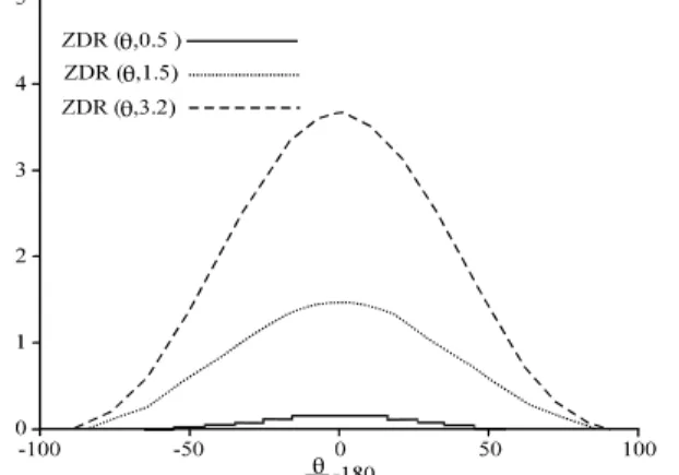
In case of rain, the results of calculation of DR (ZDR) and LDR as a function of antenna elevation angle
are shown in Fig. 1 and 2, respectively:
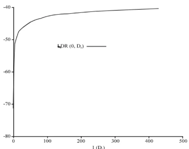
Figure 3 and 4 show the same parameters ZDR and
LDR when calculated as a function of rain rate.
Normally, rain is characterized by ordered droplet orientation in vertical plane. Usually δ is stable and lies in the range of 0 to 5°[8].
The polarization parameters were calculated on the basis of Gaussian pδ(δ) distribution (with mean δ and
rms σδ), uniform pα(α) distribution and
Marshall-Palmer drop size distribution pD(D) . Results shown in
Fig. 3 and 4 were obtained at θ = 0 (horizontal sounding), δ =5° and rather strong order of droplets given by σδ =1°.
One can see that maximum DR is observed at horizontal (or close to horizontal) sounding of rain. That is because the projections of droplets on the plane perpendicular to the beam become ellipses with the biggest difference between the axes. The higher D0 (and
the higher rain rate R) the more difference from the sphere shape for the droplets in scattering volume (on average). Hence DR becomes higher.
Fig. 1: ZDR versus antenna elevation θ for rain. Median
drop diameter D0 of 0.5, 1.5 and 3.2 mm
Fig. 2: LDR versus antenna elevation θ for rain. Median
drop diameter D0 of 0.5, 1.5 and 3.2 mm
Fig. 3: ZDR versus rain intensity for water droplet
cloud. Median drop diameter D0 was in range
Fig. 4: LDR versus rain intensity for water drop cloud.
Median drop diameter D0 was taken in range
0.4 to 3.2 mm
At vertical sounding (θ = ±90°) DR is close to zero because the projection of each spherical droplet becomes circle and no difference is observed between backscattering at horizontal and vertical polarizations.
Maximum value of LDR at θ close to zero
(horizontal sounding) is not expressed so sharply as it was observed for DR even in case of strong rain (with large value of D0). For very slight rain LDR is extremely
small because of spherical shape of small droplets and dependence on antenna elevation is not seen in the picture.
As it is shown in Fig. 3 and 4 even for strong rain values, ZDR and LDR do not exceed 4 and -40 dB,
respectively.
Now let us consider the results of radar polarization parameters calculation in case of cloud that consists of ice crystals. Fig. 5 and 6 show ZDR and LDR
(in decibels) as functions of antenna elevation calculated at totally chaotic particle orientation that can be considered as one of typical models for ice crystal clouds with different types of ice crystals. All curves are calculated independently for every type of ice crystals.
One can see that for randomly oriented crystals (in both vertical and horizontal planes) the power received for horizontal polarization is the same as that for vertical polarization. ZDR does not depend on crystal
type and antenna elevation.
As it is shown in Fig. 6 values of LDR for columnar
ice crystals are distributed from -14 to -16 dB depending on their size. The results presented in Fig. 5 and 6 can be considered as good test of the model. The
Fig. 5: ZDR versus antenna elevation θ for columnar
crystals needles and plates.The case of randomly oriented crystals
Fig. 6: LDR versus antenna elevation θ for columnar
crystals of maximal length 8, 1 and 0.1 mm. The case of randomly oriented crystals
As it has been noted above the quantity of crystals of different types in a cloud depends on temperature of the atmosphere. It is reasonable to suppose that if uniform model of crystal orientation is valid in both horizontal and vertical planes and also backscattering is incoherent, the total value of RCS obtained by averaging of values RCS from various types of crystals in view of weight coefficients w, is proportional to their percentage in total amount:
∑
∑
∑
∑
+
+
= columnar
needles ( hh needles )
total (
hh w w
∑
∑
∑
∑
+
+ =
) plates ( hv plates columnar
( hv
columnar )
needles ( hv needles )
total ( hv
w
w w
(15)
∑
∑
∑
∑
+
+ =
) plates ( vv plates columnar
( vv
columnar )
needles ( vv needles )
total ( vv
w
w w
(16)
Therefore, the total value of a ZDR and LDR may be
expressed using formulas (11) - (16) as: ) / log( 10 Z
total total
total hh vv
DR = ∑ ∑ (17)
) / log( 10 L
total total
total hv vv
DR = ∑ ∑ (18)
Calculations using such method show that for different types of crystals with different weight coefficients values of LDR lies in range -14 to -23 dB.
ZDR in case of uniform distribution canting angle is
equal to 0 dB.
Liquid cloud without rain consists of small droplets, which are practically of spherical shape. That is why polarization does not play any role at scattering on such clouds. Power received in horizontal and vertical planes almost identical, cross-polarization component is close to zero, so ZDR is extremely small and LDR →−∞ (ZDR 0 dB and LDR down to -75 dB).
These values do not depend on polarization angle.
CONCLUSIONS
The developed Mathematical models for some effects of wave propagation in cloudy atmosphere allow estimating scattering from hydrometeors of various types, particularly combinations of water droplets and ice crystals. The developed models can be used to calculate the polarimetric measurable variables at some tasks of remote sensing of clouds and precipitation.
The models are implemented as software with convenient interface. The mathematical models were previously validated using experimental data in case of rain observation.
The results of this research give the basis for development of algorithms for detection of zones in clouds where aircraft icing is characterized by high probability. They can also be useful for recognition of hydrometer types in the tasks of radar meteorology and atmosphere physics, particularly, hail detection.
REFERENCES
1. Al Lawama, A., D.N. Glushko and F.J. Yanovsky, 2005. Flight safety: passive measurement of the distance to lightning source from an airplane. Proceedings of the 2nd International Workshop on Intelligent Transportation, Hamburg, pp: 181-186. 2. Shupiatsky, A.B. and F.J. Yanovsky, 1990. The
influence of microphysical and electrical characteristics of troposphere non-homogeneity on transformation of polarization parameters of radar signals. 16 All-Union Conference on Propagation of Radiowaves, Part 2. Kharkov, pp: 96-97.
3. Shupiatsky, A.B. and F.J. Yanovsky, 1991. Radar method of localization of aircraft icing zones. USSR Patent Application No 4898827, Priority 14 May 1990, positive decision.
4. Yanovsky, F.J., H.W.J. Russchenberg and C.M.H. Unal, 2005. Retrieval of information about turbulence in rain by using doppler-polarimetric radar. IEEE Trans. Microwave Theor. Technol., 53 (2): 444-450.
5. Yanovsky, F.J., 2004. Doppler-polarimetric approach for supercooled water detection in clouds and precipitation by airborne weather radar. International Radar Symposium IRS 2004. Proceedings. Warsaw, Poland, pp: 93-100.
6. Mazin, I.P., 1989. Microstructure of clouds. In the Book Clouds and Cloudy Atmosphere. Leningrad, Gidrometeoizdat, pp: 297-344.
7. Pruppacher, H.R. and J.D. Klett, 1997. Microphysics of Clouds and Precipitation. Dordrecht, Kluwer Academic Publishers.