ISSN 0104-6632 Printed in Brazil
www.abeq.org.br/bjche
Vol. 32, No. 04, pp. 865 - 873, October - December, 2015 dx.doi.org/10.1590/0104-6632.20150324s00003682
Brazilian Journal
of Chemical
Engineering
LIQUID FLOW IN IMPELLER SWEPT REGIONS
OF BAFFLED AND UNBAFFLED VESSELS WITH
A TURBINE-TYPE AGITATOR
M. Yoshida
*, H. Ebina, H. Shirosaki, K. Ishioka and K. Oiso
Department of Applied Sciences, Muroran Institute of Technology, 27-1,Mizumotocho, Muroran 050-8585, Japan.
*
E-mail: [email protected]
(Submitted: August 1, 2014 ; Revised: December 17, 2014 ; Accepted: January 20, 2015)
Abstract - Liquid flow in the impeller swept region of vessels with a turbine-type agitator was examined for the flow path between the neighboring blades of the rotating impeller. Visualization of the flow and its measurement were done using particle tracking velocimetry with a camera rotating along with the impeller. Internal liquid flow of the impeller differed when the velocity magnitudes were compared in conditions with and without baffles. Larger circumferential and radial velocities were observed without the baffles and with the baffles, respectively, which was considered to result in the difference of impeller power transmission. Efficiencies produced, based on the flow-head concept, reflected the impeller power characteristics. The turbine-type impeller as an actuator was demonstrated to improve in the flow characteristics with viscous losses increased by the baffles. In terms of impeller efficiencies based on the power consumption, the effect of baffles for the energy was as a decreased transmission and an increased transport.
Keywords: Agitated vessel; Turbine-type agitator; Liquid flow; Impeller swept region; Baffle.
INTRODUCTION
Vessels that are agitated by mechanically rotating impellers are commonly used in industrial applica-tions of chemical processes. When low-viscosity liq-uids are treated, baffled vessels having a disk turbine impeller with six flat blades are often employed. For such a configuration of the apparatus, knowledge related to the liquid flow within the vessel has been accumulated for utilization in operational and geo-metrical design (Lee and Yianneskis, 1998). Dynamics of the bulk flow produced by the turbine-type impel-ler within the vessel were documented by a number of researchers (Yianneskis et al., 1987; Mavros, 2001). Additionally, the characteristics of the liquid flow were elucidated for the region in the vicinity of the impeller, which is essential in the apparatus (Sharp and Adrian, 2001; Yoon et al., 2001). Most of these
A survey of earlier studies was made, with em-phasis on investigations of the liquid flow in the impeller-swept region of vessels with agitators. Gray (1966) described the theoretical relation between the liquid velocity and the velocity on the periphery of an impeller, using angular momentum theory. By means of that relation, the discharge flow rate was calculated for different designs of impellers. Such a theoretical approach is practically interesting and helpful for performance evaluation considering im-peller power characteristics based on the flow-head concept. Unfortunately, he did not refer to the flow through the path between the impeller blades, limit-ing application to the flow on the impeller periphery, which corresponds to the exit of the flow path. Al-most the only literature related to experimental ap-proaches is a report by Takashima and Mochizuki (1971), who conducted tomographic observations and measurements with a camera rotating with an impel-ler. Although the local flow around the impeller blades was visualized to be characterized by unique models, the data were not analyzed to permit geo-metrical modification and design for impellers. Com-putational fluid dynamics (CFD) predictions that have been applied recently to various flow fields can provide detailed information and related knowledge. For the modeling using a grid rotating with an impel-ler (Ng et al., 1998; Singh et al., 2011), clarification of the internal flow of the impeller is anticipated, but the prediction is regarded as being subject to uncer-tainty.
Regarding the geometry for operation in low-viscosity liquids, the baffles are usually attached to the vessels to enhance axial mixing by preventing the primary circumferential flow from becoming pre-dominant. Gray (1966) considered the baffle condi-tion and concluded that the baffles have the funccondi-tion of increasing the impeller performance, as evaluated in terms of the discharge flow rate. A baffled vessel has been generally recognized as advantageous for liquid-phase mixing. Consideration should also be given to the effect of baffles on the internal flow of the impeller. Assessing whether the baffles that are external attachments influence the internal flow might be important to conceptualize combined con-figurations of the impeller and vessel with the baf-fles, even non-standard configurations (Karcz and Major, 1998; Torre et al., 2007).
To examine the liquid flow in the impeller-swept region of vessels with and without baffles, this study used particle tracking velocimetry with a camera rotating along with an impeller. The internal flow of the turbine type impeller was first measured for its characterization in terms of energy. Additionally,
angular momentum theory was used to analyze the experimental data based on the flow-head concept. Geometrical design of the impeller, including attach-ment of the baffles, in relation to the power charac-teristics was then discussed in terms of the efficien-cies determined from the analytical results for the flow.
EXPERIMENTAL
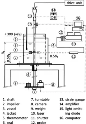
A schematic diagram of the experimental setup is shown in Figure 1. A fully baffled cylindrical vessel and an unbaffled one with a flat base made of trans-parent acrylic resin (300 mm inner diameter, Dt) were used. In the former, four vertical baffles with width of 0.1Dt were fitted along the internal wall of the vessel, being spaced equally in the circumferen-tial direction. The liquid depth was maintained at Dt:
300 mm. A disk turbine impeller with six flat blades (150 mm diameter, Di) of standard design was used. It had blade widths of Di/4 and heights of Di/5. The impeller was set at a height of 0.5Dt from the vessel bottom. The impeller rotation rate was set to 100 rpm. The impeller power consumption was deter-mined by measuring the torque with strain gauges fitted onto the shaft (Yoshida et al., 2001).
Figure 1: Schematic diagram of the experimental
Tomographic visualization of the liquid flow was done on the different horizontal planes normal to the impeller shaft, using the particle suspension method. Additionally, the flow velocity was measured using two-dimensional particle tracking velocimetry (PTV). The flow in the direction parallel to the shaft, namely, the axial flow, was out of view for examina-tion. Polystyrene particles (approximately 0.05 mm diameter) were used as tracers. The liquid phase was NaCl solution, with a density equal to that of the tracer particles (1.03 g/cm3). The liquid viscosity was 1.00 mPa·s. The impeller Reynolds number was 38600, indicating that the bulk liquid flow was tur-bulent. Images were recorded using a video camera. A 0.5 W laser light sheet adjusted to 2 mm thickness was used for lighting. Lighting was collimated to illuminate the different horizontal planes covering the lower half of the impeller blade. Its height, meas-ured as the distance between the centerline of the impeller blade and that of the light sheet, was varied: 1-17 mm. No examination was run for the upper half of the blade. In subsequent analyses, calculations were made on the assumption of vertical symmetry. The circumferential and radial velocities of liquid flow were examined based on pictures taken with the camera set on a turntable underneath the vessel. The table was attached on the same shaft as that driving the impeller. Details of settings for analysis in PTV incorporating the binary cross-correlation method (Uemura et al., 1990) were described in a previous paper (Yoshida et al., 2007). The coordinate system defined on the horizontal and vertical planes and the test area for measuring the liquid flow velocity are presented in Figure 2.
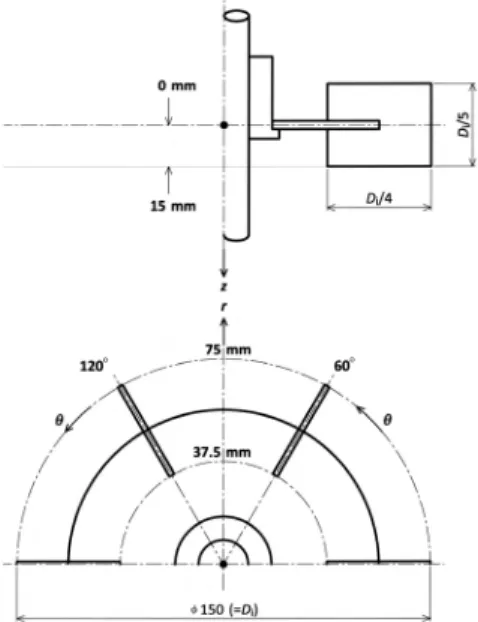
Figure 2: Coordinate system and test area to analyze liquid flow.
Cylindrical coordinates were used: The origin was designated as the intersection between the shaft cen-terline and the plane including the impeller blade centerline. The circumferential angle was measured in the orientation depicted in Figure 2. After setting the two instantaneous images in series, the liquid flow velocity through a section (2.5 × 2.5 mm = 12.5 × 12.5 pixels) in the test area was determined as the vector based on the difference in position between the tracer particles identified on the composite image and the time between camera frames (1/1000 s). Velocity vectors collected during 40 rotations of the impeller were averaged, being weighted for the distance between the measured point and the section center.
RESULTS AND DISCUSSION
Velocity Profile of the Liquid Flow
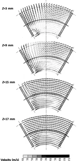
Figure 3 (a) depicts typical profiles of the liquid flow velocity when the height measured related to the impeller, the axial distance, Z, was varied under the baffled condition. In the figure, the vectors are shown for the velocity relative to that of the impeller rotation. On the horizontal plane including by the midsection of the impeller blade for a representative
Z=3 mm, a roll vortex was observed around the blade inner edge, as illustrated by Van’t Riet and Smith (1973). On its exterior, forced rotation of the liquid between the blades produced outward flows with the centrifugal force. In the front of the blade, the streams run toward the blade and impact onto its surface. In the rear, the streams are practically aligned with the blade, remaining in contact with its surface. Streams from the front and those from the rear were followed to meet in the vicinity of the blade outer edge and to run out by discharge action through the impeller. The flow along the blade sur-face became weak toward the blade lower edge as Z
increased. On the horizontal plane including by the lower edge of the impeller blade for a representative
be attributable to the behavior of the trailing vortex. Its core line reportedly continues from that of the roll vortex around the blade inner edge (Van’t Riet and Smith, 1973; Yianneskis and Whitelaw, 1993).
Figure 3 (b) depicts typical profiles of the liquid flow velocity under the unbaffled condition. Charac-teristic streams were observed more or less in com-mon with the baffle conditions. As the figure shows, the relative velocities were lower in most cases than those with the baffles, the liquid flow between the blades approaching the impeller rotation. Additionally,
unlike in the case of the baffled condition, a field having locally larger velocities was vanishingly ob-served on the horizontal planes, including by the lower edge of the impeller blade. The trailing vortex reportedly forms behind the blade for the unbaffled vessel. Its trajectory was similar to that for the baf-fled vessel (Alcamo et al., 2005). However, the rota-tion rate in that region might differ according to the baffle conditions. These results suggest that flow behaviors in the impeller-swept region are influenced by the baffles.
Figure 3 (a): Flow velocity profiles at different heights in the impeller-swept region of the baffled vessel. Rotation orientation is counterclockwise: the surfaces of the right and left blades in the test area respectively correspond to the front side and the rear.
Circumferential and Radial Velocities of the Liquid Flow
The vector of the liquid flow velocity has circum-ferential and radial components: v and vr. Figure 4 shows the changes of v and vr with the circumferen-tial angle, , at different axial distances, Zs. At 55 mm of radial distance, R, corresponding to a midstream of the flow path between the blades, v tended to increase in sections near the blade surface (=60 and 120 deg), irrespective of the baffle condition. Con-currently, vr had a tendency to increase from the front (=60 deg) to the rear (=120 deg) of the blade. For the variation of Z, the differences of v and vr were found to be larger with the baffles than without the baffles. Downstream of the flow path, as typified by the position of R=75 mm, the dependences of the velocities on Z became larger at the blade rear for both conditions with and without the baffles. A mark-edly larger dependence was observed under the baf-fled condition. Attaching the baffle affects the in-crease of velocity dependence on Z, namely the ve-locity gradient formed in the axial direction. An in-creased velocity gradient can enhance the generation of turbulence in the flow and induction of secondary flow. The influence of such a flow behavior, which has been recognized to be a function of the baffle
(Nagata et al., 1959a; Nagata et al., 1959b), was reasonably supported through examination of the internal flow of the impeller.
The complicated profile of the liquid flow ve-locity was coordinated in terms of the circumferen-tial and radial components averaged for the circum-ferential and axial directions. Figure 5 shows the changes of the average velocities, v and vr, with the radial distance, R. Independent of the baffle condi-tion, v increased along the flow path between the blades as R increased and leveled off near the path exit (R=75 mm). On the other hand, vr increased over the entire R range. For the difference dependent on the baffles, it was found that v was larger without the baffles, but vr exhibited the opposite tendency. These results were interpreted as a difference in en-ergy with the flow-head concept (Edwards et al., 1992; Wu et al., 1997; Srilatha et al., 2008; Fort, 2011). The total head imparted to the liquid on the impeller blade is related to the circumferential veloc-ity. The volumetric flow rate of the liquid passing between the blades is determined by the radial veloc-ity. The head and flow should respectively reflect the intensity and rate of the energy transmitted by the impeller. Thus, although the transmission per liquid mass is advantageous without the baffles, that per time is favorable with the baffles.
Figure 4 (a): Changes of the circumferential and radial velocities as viewed from the circumferen-tial and axial positions (radial distance, R=55 mm).
Figure 5: Changes of average flow velocities as viewed from a radial position
Impeller Efficiencies Based on the Flow-Head Concept
The angular momentum theory was applied to analysis of the internal flow of the impeller employing the control surfaces and volume depicted in Figure 6. A modeled flow pattern was assumed in which liquid flows in the control volume across surfaces 1 and 3 and flows out across surface 2. An additional as-sumption was made that the liquid flows radially and uniformly through the path between the neighboring blades of the rotating impeller. In conjunction with this, the viscous force on the blade surfaces was de-termined as beyond consideration. The system was simplified further by neglecting the forces on the control surfaces. The related matter was followed by the mechanical balance caused by the action-reaction forces between the blades and liquid. The moment on the shaft fitted with the impeller is given as the temporal rate of change of the angular momentum. Expressing the relation to the circumferential and radial velocities, v and vr, based on the flow (Q) -head (H) concept,
r
r
P Q gH
Q gH Q gH
v S uv v S uv
(1)
where P is the power transmission of the impeller, S
is the area of the surface normal to the r direction, u
is the velocity of impeller rotation, that changes de-pending on r position. is the liquid density and g is
the acceleration due to gravity, and they were treated as constant. Equation (1) expresses the power charac-teristics related to the internal flow of the impeller.
Figure 6: Control surfaces and volume determined
in the impeller-swept region
For the flow described above, neglect of the forces on the control surfaces gives a condition that the angular momentum of the liquid inflowing at any r
position is equal to that of a liquid at the related position within the rotating impeller. Then, Eq. (1) is reduced to
r
P Q gH Q gH
v S uv
(2)
Integration of Eq. (2) from the entrance of the flow path to its exit yields the following equation:
1
12
r i r i
i i
P Q gH
v S v S
uv uv
(3)
flow. Concurrently, (gH)m and (Q)m for the modeled
flow were determined as follows.
2 22 1
m
gH u u (4)
m mm
P Q
gH
(5)
Suffixes 1 and 2, respectively, denote control surfaces 1 and 2, corresponding to the entrance and exit of the flow path. In the actual flow, v and vr are generally not equal to u. Calculation of Pas from Eq. (3) was made using vs and vrs measured under conditions with and without baffles. (gH)a and (Q)a for the
actual flow were determined as for the modeled flow.
gH a
uv 2 uv 1 (6)
a aa
P Q
gH
(7)
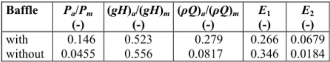
The analytical results are summarized in Table 1 as quantities for the actual flow relative to those for the modeled flow. These ratios were perceived to be efficiencies expressing the differences between the actual and modeled flows in terms of the flow and head. The differences depending on the baffle condi-tion, as shown in Figure 5, are indicated by the ra-tios. Thus, the head characteristic related to the cir-cumferential velocity was efficient without the baffles, but the flow determined by the radial veloc-ity was efficient with the baffles. The increased flow rate under the baffle condition is attributable mainly to the larger inflow across surface 3. The axial in-flow can disturb the in-flow along the blade surface in the path. It seems to follow that the head characteris-tic was decreased. Roughly assessing the efficiency for a turbine type impeller of standard design, as used in this work, the respective flow and head effi-ciencies were about 10-30 % and 50 %. Results show that the power efficiency was about 10 %, which implies that 10 % of the total in the impeller blades works for the energy transmission. For modification and design of the blade geometries of the turbine-type impeller, a guideline should be proposed so that improvement of the flow efficiency is considerable. Then, introduction of these parameters based on the flow-head concept might provide sound ideas for the design of improved impellers.
Table 1: Impeller efficiencies calculated based on analysis of the internal liquid flow.
Baffle Pa/Pm
(-)
(gH)a/(gH)m (-)
(ρQ)a/(ρQ)m (-)
E1
(-)
E2
(-)
with 0.146 0.523 0.279 0.266 0.0679 without 0.0455 0.556 0.0817 0.346 0.0184
Impeller Efficiencies Based on the Power Con-sumption
The power transmission of the impeller, P, as cal-culated from Eq. (3) for the actual flow, was com-pared with the power consumption of the impeller,
P’. The ratio, P/P’, which was added to Table 1 as
E1, was regarded as another efficiency considering viscous losses in the internal flow of the impeller. E1
without the baffles was larger than that with the baf-fles. This difference seems to reflect the difference of the velocity gradient formed in the flow. The larger the gradient is, the larger the viscous loss is with increased turbulence, resulting in a decreased E1. The larger E1 without the baffles is considered to result from the smaller velocity gradient formed in the axial direction, as shown in Figure 4. Conceptually,
E1 is identical to the hydraulic efficiency defined by Fort (2011). This parameter expresses the portion of the impeller power input that is dissipated entirely within the vessel except for the impeller swept re-gion. Such an impeller power output is used effec-tively outside the impeller swept region. The effi-ciency, E1, is expected to be important in design, conditioning the energy dissipations in the internal and external flows of the impeller. Moreover, a higher E1 value is not always desirable. For opera-tions with mixing and dispersion of one phase in another phase, the shear action in flows produced by an impeller is enhanced for the impeller having a lower E1 value. It is to be noted that E1 is an indica-tor for the impeller design with energy considera-tions.
Hitherto, some efficiencies of the impeller have been proposed to assess the power characteristics (Nienow, 1997; Fentiman et al., 1998; Wu et al., 2006; Fort, 2011). A parameter incorporating the impeller power number, Np, and discharge flow num-ber, Nd, is possibly employed.
3
2 d
p
N E
N
(8)
without the baffles and larger E2 with the baffles. Because these efficiencies are based on the impeller power consumption, the difference in assessments is attributable to the different quantities expressed by the numerator terms in the definition equations. In
E1, the impeller power transmission is the factor considered. E2 considers the kinetic energy of the liquid discharged by the impeller. Therefore, E1 repre-sents the efficiency of the energy transmission and E2
represents the efficiency integrating the energy trans-mission, conversion and transport within the vessel. The effect of baffles on the impeller power charac-teristics is evaluated as follows: although the baffles make the impeller less efficient for the energy trans-mission, the overall efficiency is improved within the baffled vessel, being caused by efficient energy trans-port. Use of the efficiency presented here, E1, in ad-dition to the existing one, E2, is useful for considera-tion of the energy of the liquid flow within the ves-sel. It enables a fundamental assessment of the im-peller power characteristics.
CONCLUSIONS
For baffled and unbaffled vessels with the tur-bine-type agitator, we experimentally investigated the liquid flow in the impeller-swept region, consid-ering power characteristics of the impeller. The liq-uid flow velocity profiles on the horizontal planes including the impeller of the respective vessels were more or less similar in their flow pattern, but they differed in the velocity magnitude between the baffle conditions. The circumferential and radial compo-nents into which the velocity vectors were divided were compared in their magnitudes. Overall, the circumferential and radial velocities were typically higher without the baffles and with the baffles, re-spectively. Energy considerations based on the flow-head concept explained these tendencies because the baffle was effective not for specific energy transmis-sion but temporally. Collaterally, efficiencies related to the impeller power characteristics were defined. Assessment in terms of the efficiencies demonstrated for the turbine-type impeller that an improvement was desirable in the flow characteristics rather than the head. Finally, the impeller efficiencies based on the power consumption, E1 and E2, were discussed. In the impeller-swept region where the energy trans-mission is performed, the baffles were suggested to increase viscous losses, since E1 decreased by about
23%. On the other hand, the baffles were found to improve the overall liquid flow within the vessel, increasing E2 up to about 3.7 times.
NOMENCLATURE
Di impeller diameter (mm)
Dt vessel diameter (mm)
E1 impeller efficiency defined as P/P’ (-)
E2 impeller efficiency defined by Eq. (8) (-)
g acceleration due to gravity (m/s2)
H head in flow (m)
Np impeller power number (-)
Nq discharge flow number (-)
P impeller power transmission (W)
P’ impeller power consumption (W)
Q volumetric flow rate (m3/s)
R radial distance (mm)
r radial direction in the coordinate system as shown in Figure 2
S area of the surface normal to the radial direction (m2)
u velocity of impeller rotation (m/s)
vr radial velocity component of liquid flow
(m/s)
v circumferential velocity component of
liquid flow (m/s)
Z axial distance (mm)
z axial direction in the coordinate system as shown in Figure 2
Greek Letters
circumferential angle (deg)
circumferential direction in the coordinate system as shown in Figure 2
density of liquid (kg/m3)
REFERENCES
Alcamo, R., Micale, G., Grisafi, F., Brucato, A., Cio-falo, M., Large-eddy simulation of turbulent flow in an unbaffled stirred tank driven by a Rushton turbine. Chem. Eng. Sci., 60, 2303-2316 (2005). Ameur, H., Bouzit, M., Mixing in shear thinning
fluids. Braz. J. Chem. Eng., 29, 349-358 (2012). Edwards, M. F., Baker, M. R., Godfrey, J. C., Mixing
of Liquids in Stirred Tanks. Edwards, M. F., Nie-now, A. W. Ed., Mixing in the Process Industries, pp. 137-158, Butterworth- Heinemann, Oxford (1992).
Fentiman, N. J., St Hill, N., Lee, K. C., Paul, G. R., Yianneskis, M., A novel profiled blade impeller for homogenization of miscible liquids in stirred vessels. Chem. Eng. Res. Des., 76, 835-842 (1998).
impellers. Chem. Eng. Res. Des., 89, 611-615 (2011).
Gray, J. B., Flow Patterns, Fluid Velocities, and Mix-ing in Agitated Vessels. Uhl, V. W., Gray, J. B. Ed., Mixing, Theory and Practice 1, pp. 179-278, Academic Press, New York and London (1966). Karcz, J., Major, M., An effect of a baffle length on
the power consumption in an agitated vessel. Chem. Eng. Process., 37, 249-256 (1998).
Lee, K. C., Yianneskis, M., Turbulence properties of the impeller stream of a Rushton turbine. AIChE J., 44, 13-24 (1998).
Mavros, P., Flow visualization in stirred vessels, A review of experimental techniques. Chem. Eng. Res. Des., 79, 113-127 (2001).
Nagata, S., Yamamoto, K., Ujihara, M., Flow pat-terns of liquid in a cylindrical mixing vessel with-out baffles. Kagaku Kogaku, 23, 130-137 (1959a). Nagata, S., Yamamoto, K., Hashimoto, K., Naruse,
Y., Flow patterns of liquid in a cylindrical mixing vessel with baffles. Kagaku Kogaku, 23, 595-602 (1959b).
Ng, K., Fentiman, N. J., Lee, K. C., Yianneskis, M., Assessment of slidingmesh CFD predictions and LDA measurements of the flow in a tank stirred by a Rushton impeller. Chem. Eng. Res. Des., 76, 737-747 (1998).
Nienow, A. W., On impeller circulation and mixing effectiveness in the turbulent flow regime. Chem. Eng. Sci., 52, 2557-2565 (1997).
Rao, D. A., Sivashanmugam, P., Experimental and CFD simulation studies on power consumption in mixing using energy saving turbine agitator. J. Ind. Eng. Chem., 16, 157-161 (2010).
Sharp, K. V., Adrian, R. J., PIV Study of small-scale flow structure around a Rushton turbine. AIChE J., 47, 766-778 (2001).
Singh, K. K., Mahajani, S. M., Shenoy, K. T., Pat-wardhan, A. W., Ghosh, S. K., CFD modeling of pilot-scale pump-mixer, Single-phase head and power characteristics. Chem. Eng. Sci., 62, 1308-1322 (2007).
Singh, H., Fletcher, D. F., Nijdam, J. J., An assess-ment of different turbulence models for predicting flow in a baffled tank stirred with a Rushton tur-bine. Chem. Eng. Sci., 66, 5976-5988 (2011). Srilatha, C., Savant, A. R., Patwardhan, A. W., Ghosh,
S. K., Head-flow characteristics of pump-mix mixers. Chem. Eng. Process., 47, 1678-1692 (2008).
Takashima, I., Mochizuki, M., Tomographic observa-tions of the flow around agitator impeller. J. Chem. Eng. Japan, 4, 66-72 (1971).
Torre, J. P., Fletcher, D. F., Lasuye, T., Xuereb, C., Single and multiphase CFD approaches for model-ling partially baffled stirred vessels: Comparison of experimental data with numerical predictions. Chem. Eng. Sci., 62, 6246-6262 (2007).
Uemura, T., Yamamoto, F., Sachikawa, M., High-speed image analysis algorithm for particle track-ing velocimetry. Trans. Visualization Soc. Japan, 10, 196-202 (1990).
Van’t Riet, K., Smith, J. M., The behaviour of gas-liquid mixtures near Rushton turbine blades. Chem. Eng. Sci., 28, 1031-1037 (1973).
Wu, J., Pullum, L., Yunken, R., Welsh, M. C., Rapid diagnosis of flow separation around an axial im-peller in a mixing vessel. Exp. Fluids, 22, 519-522 (1997).
Wu, J., Graham, L. J., Nguyen, B., Mehidi, M. N. N., Energy efficiency study on axial flow impellers. Chem. Eng. Process., 45, 625-632 (2006).
Yianneskis, M., Popiolek, Z., Whitelaw, J. H., An experimental study of the steady and unsteady flow characteristics of stirred reactors. J. Fluid Mech., 175, 537-555 (1987).
Yianneskis, M., Whitelaw, J. H., On the structure of the trailing vortices around Rushton turbine blades. Chem. Eng. Res. Des., 71, 543-550 (1993). Yoon, H. S., Sharp, K. V., Hill, D. F., Adrian, R. J.,
Balachandar, S., Ha, M. Y., Kar, K., Integrated ex-perimental and computational approach to simula-tion of flow in a stirred tank. Chem. Eng. Sci., 56, 6635-6649 (2001).
Yoshida, M., Ito, A., Yamagiwa, K., Ohkawa, A., Abe, M., Tezura, S., Shimazaki, M., Power characteris-tics of unsteadily forward-reverse rotating impel-lers in an unbaffled aerated agitated vessel. J. Chem. Technol. Biotechnol., 76, 383-392 (2001). Yoshida, M., Shigeyama, M., Hiura, T., Yamagiwa,