*e-mail: [email protected]
Presented at the International Symposium on High Temperature Corrosion in Energy Related Systems, Angra dos Reis - RJ, September 2002.
Effects of Isothermal Treatment on Microstructure and Scratch Test
Behavior of Plasma Sprayed Zirconia Coatings
Guilherme Veloso, Heleno Rocha Alves, José Roberto Tavares Branco*
REDEMAT (UFOP/CETEC/UEMG), Inst. Agronômico, Av. José Cândido da Silveira, 2000, Belo Horizonte - MG, Brazil
www.cetec.br
Received: September 2, 2002; Revised: September 4, 2002
The increase of the petroleum cost in the last decades revitalized the interest for lighter and more economic vehicles. Simultaneously, the demand for safe and unpolluted transports grows. The application of thermal barriers coatings (TBC) on combustion chamber and on flat surface of pistons reduces the thermal losses of the engines, resulting in higher temperatures in the combus-tion chamber. This fact contributes to the improvement of the thermal efficiency (performance) and for the reduction of incomplete combustion. Supported on these initial ideas, thermal barriers coatings constituted by CaO partially stabilized zirconia were produced and their microstructure examined.
This coating still presents some drawbacks associated with thermal stresses and permeability to oxidizing gases, which will, eventually, lead to failure of the TBC by spallation. The failure may, in general, be associated to one of three factors: oxide growth at the ceramic-metal interface, formed during thermal cycling; stress build-up due to thermal cycling; and metal-oxide interface segregation, mainly of S. However, it is also relevant to understand the behavior of TBC’s under isothermal oxidation. Therefore, this paper investigates the effect of oxidation on the adherence of thermal sprayed coatings. The adherence was measured by linear scratching tests, widely used for thin coatings. Plasma sprayed calcia partially stabilized zirconia was used as TBC and Ni-5%Al as bond coat, with Al substrates. Coated samples were submitted to heat treatments at 500 °C, for 50 h. The microstructures were examined by optical light microscopy, X-ray diffraction, profilometry and SEM.
Keywords: thermal barrier coatings, plasma spraying, microstructure, adhesion, scratching test
1. Introduction
The interest in the development of thermal barriers coat-ings (TBC) for applications in internal combustion engines has grown, motivated, among other factors, by environmen-tal pressures. TBC’s developed for propulsion turbines, to protect and improve durability of materials in the hot sec-tions, are also used in the combustion chamber of recipro-cating combustion engines to reduce heat loss (up to 40%), to increase engine power and efficiency (up to 10%) with significant fuel economy, and to decrease pollutant emis-sion1. Additional benefits include the temperature
reduc-tion of the pistons and its rings and lubricant. The operareduc-tion of these engines submits the coatings to thermal cycling, promoting, eventually, an adhesive flaw.
Zirconia is commonly used as TBC due to its superior thermal insulating properties and high thermal shock re-sistance2. It has three distinct crystallographic forms:
mono-clinic, tetragonal and cubic. On heating, the transformation from the monoclinic phase to the tetragonal one, around 1000 °C, results in a volume increase of around 7%, that can disrupt the coating3-6. To increase the TBC durability,
the partially stabilized cubic phase, which is stable at higher temperatures up to the melting point, is employed. Using this expedient, the tetragonal to monoclinic transformation in the thermal spray process is avoided.
powder is fed and heated in a plasma torch up to the melting. Particles of the molten liquid are projected towards a pre-pared substrate, where they are rapidly quenched, solidify-ing and producsolidify-ing a coatsolidify-ing. There are variations of this tech-nology, which is used in more than 34 industrial branches7.
Although the plasma torch reaches temperatures above 104 K, the residence time of the powder particles are of the
order of milliseconds, and the low thermal conductivity of the zirconia prevents its overheating. This process generates porosity in the range 2% - 10% in volume and micro cracks that, although benefitial to the thermal shock resistance and low thermal diffusivity, reduce the erosion resistance and al-low penetration of corrosive gases8-10. In combustion engines
the latter leads to thermally grown oxides – TGO.
TBC’s exhibit multiple flaws mechanisms, some of them resulting in the ceramic layer separating from the substrate, which is referred to as spalling. During this process, cracks grow in the ceramic layer, close to the metal-ceramic inter-face or, when there is a bond-coat, close to the bond-coat-ceramic interface. This process starts with the oxidation of the metal substrate (or bond coat), introducing compressive stresses between the TGO and the metal. This stress, gener-ated by the oxide growth process and by the difference in thermal expansion between the coating and the oxide layer, can reach 3 to 6 GPa. Eventually, this stress leads to buck-ling, crack growth and coalescence and, finally, spallation. Thermal cycling contributes to stress build up, due to the difference in thermal expansion coefficients of the coating components, Table 1.
The growth of the TGO layer is an important phenom-enon in controlling the durability of the TBC system11-12.
The metallic bond-coat act as an aluminum reservoir and is responsible for the formation of aluminum oxide. The pref-erence for the aluminum oxide is related to its low growth rate and good adherence to its metal counterpart. The oxy-gen diffusion towards the substrate is inhibited by the TGO. The oxide growth consumes aluminum of the bond-coat, re-ducing the oxide layer capacity to be renewed when it is dam-aged. There is also a segregation at the metal/oxide interface. The effect of oxidation has been widely investigated in thermal cycled systems. However, the effect of the isother-mal oxide has not been widely looked at. Since adhesion is probably the most important aspect to indicate the service life of TBC’s, another issue that deserves attention is the measurement of coating adherence. Pull-off testing has been the preferred option in industrial organizations, while inter-facial indentation and bending tests have mostly been used in research groups. Each one has advantages and limita-tions9,13. Scratch testing has the advantage of being a very
simple and inexpensive technique, since it does not require special sample preparation and a critical load can be deter-mined in just one experiment. This test has been widely used to investigate thin films, (< 20 µm thickness, t). In this
work, ZrO2 and ZrO2/NiAl coatings, as sprayed and after heat treating at 500 °C/50 h were subjected to scratch test-ing with constant normal load.
2. Experimental Procedure
The substrate consisted of samples of a rolled Al alloy, with dimensions 100 × 25,4 × 5 mm3. The coupons to be
coated were prepared by rounding their edges and grit blast-ing, followed by manual degreasing with a solution of wa-ter and dewa-tergent. The average roughness was Ra = (5,4 ± 0,3) µm. The samples were divided in two groups: samples
coated with zirconia with a bond coating - BC (duplex) and without it (simple). The zirconia TBC was deposited with a thickness of 300 µm and the BC with a thickness of 150 µm.
The deposition parameters were as indicated in Table 2, and composition as in Table 3. The heat treatment, realized in
Table 2. Deposition Parameters.
Coat Material Current (A) Voltage (V) Primary Secondary Carrier Feed Rate Spray Distance (mm) Gás (Ar2) Gás (H2) Gas (Ar2)
ZrO2-CaO 500 50 80 15 40 80 100
NiAl 500 50 80 15 40 100 180
Table 1. Average Thermal Expansion Coefficients, (106 K-1).
ZrO2 + CaO TGO (a Al2O3) NiAl Aluminum
9-12 8-9 13 22-24
Table 3. Feed Stock Materials.
Powders composition (wt.%) Particle shape Particle size range (µm)
Ni-4,5%Al composite Spheroid (clad) -88 + 45
air, started at room temperature, reached 500 °C at 20 °C/min, with 50 h of holding time, followed by cooling at 2 °C/min down to room temperature.
For the metallographic examination, transverse sections were cut, using SiC disk, mounted in epofix® with a cure
time of 7 h, and grinded and polished afterwards with SiC sand paper in the sequence 320, 600, 800 and 1500 #, fol-lowed by 1mm diamond paste. Some samples were etched with HF:HNO3:H2O solution, with a 15:15:70 proportion, at approximately 75 °C, during 10 min, followed by clean-ing, letting the samples sit for 3 h in water and subsequently in ethyl alcohol for 24 h. The coatings were characterized before and after heat treatment by optical light microscopy - OM, perfilometry, X-ray diffraction – XRD and Scanning Electron Microscopy – SEM. The scratch testing was ac-complished using constant load and Rockwell C indentator,
starting with 5 N and increasing in 5 N steps until complete substrate exposition. The substrate hardness test employed a 2,5 mm tungsten carbide sphere, under a load of 31,25 N.
3. Results and Discussion
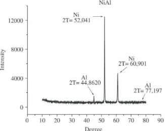
The Ni-Al feedstock is a composite powder, with small amounts of Aluminum phase, while the zirconia is mainly cubic with small amount of the monoclinic phase, Figs. 1 and 2. TBC coatings were ground for the XRD analysis.
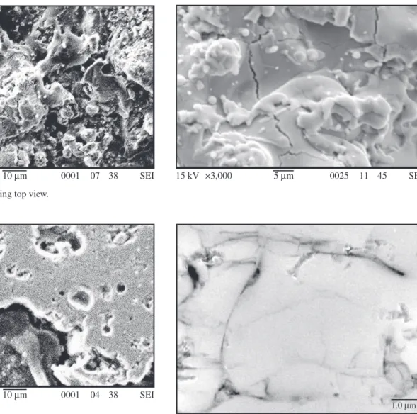
Details of the structure and interface of the TBC can be seen in Fig. 3, showing that the zirconia structure is com-plex and heterogeneous. The as sprayed NiAl bond coat-ings present the characteristic lamellar structure of the plasma sprayed coatings, Fig 4. The zirconium layer, seen from top in Figs 5 and 6, show that some zirconia particles
Figure 1. X - Ray Diffraction Spectra of feedstock NiAl. Figure 2. X - Ray Diffraction Spectra of feedstock ZrO2.
Figure 3. Cross section of ZrO2 coating, ME - SEI. Figure 4. Cross-section NiAl intermediary layer.
Figures 5 e 6. ZrO2 coating top view.
Figure 7. Spherical pores on Zirconia coating, MEV – SEI. Figure 8. Micro cracks on Zirconia coating, MEV – SEI.
15 kV ×1,000 10 µm 0001 07 38 SEI 15 kV ×3,000 5 µm 0025 11 45 SEI
15 kV ×1,500 10 µm 0001 04 38 SEI
15 kV ×3,300 5 µm 0003 09 58 SEI 15 kV ×5,500 2 µm 0004 09 58 SEI
were melted and solidified before being incorporated into the coating while many show the peculiar lamellar shape, Fig. 6.
Figures 7 and 8 show the main features of the micro-structure of the CaO partially stabilized zirconia coatings, which include voids with various shapes and dimensions, pores, lack of penetration of liquid splats, and cracks. The pores have rounded contours and exhibit a variety of di-mensions, depending on their origin being due to dissolved gases in the liquid particles or gases that were produced from chemical reactions. The micro cracks, which are illus-trated in Fig. 8, can be seen running perpendicular or paral-lel to the substrate as they form from thermal contraction during and after spraying, as well as from solidification and thermal shocks. After the heat treatment, the aluminum substrate softened from 40,4 to 36,8 HB2 (5/31,25). A dis-tinct region is noticeable at the substrate-TBC interface, Figs. 9 and 10. Composition maps of this region are shown in Fig. 11. The oxygen and aluminum images suggest forma-tion of an alumina layer with thickness between 2 and 5 µm.
XRD showed that plasma spraying prevented formation of the monoclinic phase, which was initially present in the zirconia feedstock. No effect of the heat treatment on the
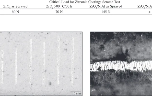
Figure 12. Scratch test with constant load.
Table 4. Critical Load for Zirconia Coatings Scratch Test
Critical Load for Zirconia Coatings Scratch Test
ZrO2 as Sprayed ZrO2 500 °C/50 h ZrO2/NiAl as Sprayed ZrO2/NiAl 500 °C/50 h
60 N 70 N 145 N > 200 N
Figure 13. Tensile cracks (traction) 40 N. TBC microstructure was detected.
The critical load for the scratch tests varied as shown in Table 4. A series of scratches with increasing loads were made, Fig. 12. Tensile and cohesive cracks were visible in-side the scratches groves, in all coatings, as illustrated in Fig. 13. The transition from scratches just under critical load, left side, and after the critical load, right side can be seen in Fig 14. No spallation was observed during scratching of the heat treated ZrO2/NiAl sample, Fig 15.
The first mathematical analysis of the scratch testing, after Benjamin and Weaver, considered only the plastic de-formation associated with indentation and scratching9. A
Figure 14. ZrO2/NiAl as Sprayed Scratch in critical load. Figure 15. ZrO2/NiAl 500 °/50 h.
Where: Lc = critical load d c = scratch width E = Young modulus W = adhesive work
According to Eq. 1, the increase of the critical load is proportional to work of adhesion, considering the elastic modulus and the coating thickness constants. The improve-ment in adherence due to Ni-Al bond coating, as previously reported, was confirmed. The heat treatment at 500 °C did not promote any detectable structural or phase changes and therefore it most likely did not affect the TBC elastic modu-lus. Therefore, the present results suggest that the heat treat-ment promoted an increase in the TBC adherence. This improvement may have been possible due to the continu-ous growth of the TGO, filling voids with the oxide and, therefore, increasing the mechanical interlocking with the TBC, as well as to the possibility that the soft Aluminum substrate could relax the stress. The lack of thermal cycling and thermal shock certainly decrease the stress load at the TGO/metal interface, and the combination of these factors most likely resulted in the improvement of adherence, as hereby reported.
4. Conclusions
• A plasma sprayed zirconia TBC was deposited on an Aluminum substrate, with a structure similar to what has been reported for low temperature substrates. Two groups of samples were prepared: the first had the zirconia depos-ited directly on the substrate, while the second had an inter-mediate Ni-Al bond coating.
• Adherence of the coatings was investigated using the scratch testing. This technique was able to promote coating
adhesive failure at fairly well defined loads. The results al-lowed a comparison to be made of the effects of the pres-ence of a bond coating and of an oxidation heat treatment. • The use of a Ni-Al bond coating improved adherence. The heat treatment at 500 °C, which created a TGO at the Aluminum-TBC interface, also improved adherence. The latter was rationalized by the formation of an adherent ox-ide layer that improves metal to TBC contact. The stress resulting from the mismatch between the substrate and the oxide is proposed to relax in the soft aluminum substrate.
Acknowledgment
The authors acknowledge the financial support from Fundação Gorceix and FAPEMIG; to MAGNESITA S.A.,SENAI - MG and to SINDIREPA - Sindicato da Indústria Reparadora de Veículos e Acessórios we acknowl-edge receiving samples and fruitful discussions. Thanks are also extended to Dr. Abá Persiano and UFMG, for electron micro-probe analysis, and to the metallographic laboratory from CETEC-MG.
References
1. Katayama, Y.; Kuroki H. Surface and Coatings Technol-ogy, Surface Treatment of Plasma-sprayed Ceramics Coatings by a Laser Beam, v. 34, p. 59-67,1988. 2. Pierz, P. M. “ Thermal barrier coating development for
diesel engine aluminum pistons”, Surface and Coat-ings Technology, v. 61, p. 60-66, 1993.
Pro-ceedings, p. 285-290,setembro 1987.
4. Schütze, M. “An approach to a global model of the me-chanical behaviour of oxide scales”, Materials at High Temperatures, v. 12, p. 237-247, 1994.
5. Schütze, M. “Mechanical Properties of Oxide Scales”, Oxidation of Metals, v. 44, p. 29-61, 1995.
6. Hoag, K.L.; Frisch, S.R.; Yonushonis, T.M. “Thermal Analysis of the Effect of Thick Thermal Barrier Coat-ings on Diesel Engine Performance”, Proceedings of the 24th Automotive Technology Development
Contrac-tor’s Coordination Meeting, SAE, p. 90-97, 1986. 7. Steeper, T.J.; Riggs II, W.L. “A Taguchi Design of
Ex-periment Study of Plasma Sprayed Alumina Coatings”, Procedings of the 1993 National Thermal Spray Con-ference, Anaheim, CA, June 1993.
8. Fauchais,P.; Vardelle,M.; Vardelle, A.; Bianchi,L. Ceram-ics International, v. 22, p. 295-303, 1996.
9. Bull, S.Jl; Rickerby, D.S. in D.S. Rickerby and A. Matthews, Advanced Surface Coating - A Handbook
of Surface Engineering. P. 315-342 Published by Chapman and Fall - N.Y., 1991.
10. Smidt, F. A.; “Surface Modification”, Advanced Mate-rials and Process, v. 1, p. 61-62, 1990.
11. Evans, A. G.; Mumm, D. R.; Meier, G. H.; Hutchinson, J. W. Mechanisms controlling the durability of ther-mal barrier coatings - Progress in Materials Science 46, p. 505-553, 2001.
12. Evans, A. G.; He, M. Y.; Hutchinson, J. W. - Mechanics-based scaling laws for the durability of thermal bar-rier coatings, Progress in Materials Science 46, 249-271, 2001.
13. Holmberg, K.; Matthews, A. Coating Tribology – Prop-erties, techniques and applications in surface engineer-ing. Elsevier, 1994.