1752 Brazilian Journal of Physics, vol. 34, no. 4B, December, 2004
Fast Opening Gas Valve for the TCABR Pellet Injector
Alvaro Vannucci, Carlos Mariz de O. Teixeira, Fernanda S´a Teixeira, Jos´e H. Vuolo,
Alexandre C. de Paulo*, Fernando Horita, Francisco T. Degasperi*, Juan I. Elizondo,
Edson K. Sanada, Vittorio A.L. Almeida, and F´abio Pantano
Instituto de F´ısica, Universidade de S˜ao Paulo, 05508-900, S˜ao Paulo, SP, Brasil*Faculdade de Tecnologia de S˜ao Paulo, FATEC, 01124-060, S˜ao Paulo, SP, Brasil
Received on 03 February, 2004; revised version received on 04 June, 2004
Fast acting gas valves that operate between two very different pressure environments, which may differ in several orders of magnitude, are not available commercially and, therefore, they must be specifically projected and constructed. For the TCABR impurity pellet injector, under construction, an electromagnetic valve has been built which operates for gas pressure that ranges from20to40atmat one side of the valve to10−9atm
at the other side. The working principle of the valve is based on the displacement of an aluminum disk (which controls the gas flux) from its closing position by an electromagnetic force, in result to an induced electric current on the disk caused by a magnetic flux variation. Experimental results showed that the electromagnetic impulse on the disk lasts for200µsand takes less than30msfor the valve to shut up again.
1
Introduction
Fast and controlled gas injection can be considered as an useful technique in several and different areas of experimen-tal physics research. In particular, for the magnetic confine-ment of plasmas, devices like tokamaks are generally em-ployed in which the use of fast and controlled gas injection is required to operate properly. In this paper, in particular, the construction details are given of a gas injection system that will be used in a pellet injector for the TCABR tokamak, at the Physics Institute of the University of S˜ao Paulo.
As already have been observed previously in other to-kamaks, the interaction of the plasma with impurity pellets (boron, carbon, aluminum, tungsten, etc.) provokes a lo-cal and sudden increase of the concentration of impurity ions, leading to a strong dissipation of the stored energy and, many times, to a modification of the plasma equilibrium and stability [1-4].
In JET, for instance, it has been observed that the use of solid D2 pellets led to the creation of a structure similar to a snake in the profiles of the softray-X emission. From this observation it was possible to determine, in the plasma, the exact location of the q = 1 magnetic surface [2].
In the tokamak ASDEX, on the other hand, neon pel-lets were injected with the objective of controlling and mi-tigating the disruptive instabilities. In that work, however, since there were no possibility of foreseeing when the dis-ruptions would take place, the neon pellets were shot during the plasma discharges without the concern of whether the disruption has already been triggered or not. It could be ve-rified that the injected pellets irradiated up to 90% of the total plasma stored energy in time intervals less than 1ms [3]. Furthermore, it was demonstrated that the mechanical stresses induced in the whole tokamak structure, due to the
abrupt ending of the plasma confinement, were reduced in 50%, on average, when the neon pellets were injected.
Now, in the MT-1M and TEXTOR-94 tokamaks, the use of aluminum micro-pellets made possible a direct analysis of the plasma-pellets interaction, which typically formed light emitting grooves [4]. The experimental results obtai-ned could be properly explaiobtai-ned in terms of the aluminum sublimation rate, that was calculated from the expansion of the vaporized aluminum cloud.
For the TCABR tokamak, an impurity pellet injector is now under construction with the objective of investigating the transport of particles in different discharge conditions, and also of studying how this system could be used to con-trol the triggering process of disruptive instabilities. The most sensitive part of the project is related to the construc-tion of a fast acting electromagnetic gas valve, and the cor-responding high current (up to6kA) and high voltage (up to7kV) power supply. The details of the project and cons-truction of these components are given and fully discussed in this article.
2
Electromagnetic valve
´
Alvaro Vannucciet al. 1753
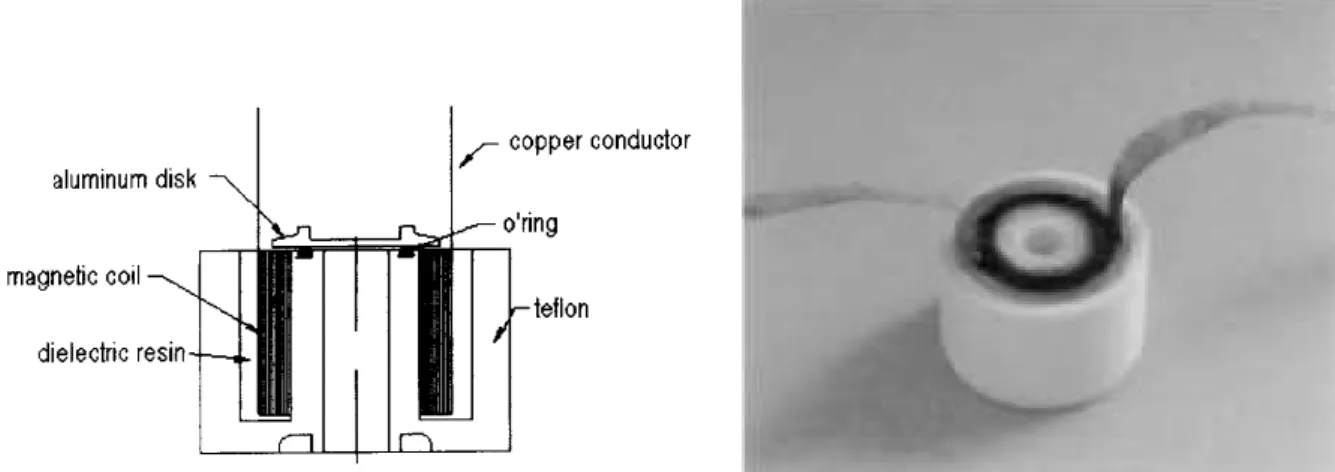
Figure 1. Magnetic coil constructed for the TCABR pellet injector: (a) schematic drawing and (b) the valve in its final form.
Figure 2. High pressure gas chamber constructed for the TCABR pellet injector: (a) schematic drawing and (b) the chamber in its final form.
which up to 6 kA currents are produced. The construc-tion of the magnetic coil was accomplished by winding a copper ribbon (length L = 1m, width w = 8 mm and thicknesst = 0.1 mm), totalizing 12 turns. A good elec-tric insulation between each winding was obtained using a continuous mylar ribbon (widthh= 20mmand thickness z = 0.3mm) and, afterwards, dipping the whole assembly in a liquid epoxy resin that, after the hardening, gave body to the reel and also served as element of mechanical fixation of the reel to a teflon base (Fig. 1).
The coil parameters, mentioned above, were chosen as to produce a mechanical force on the aluminum disk against the high gas pressure, of the order of1100N or greater, to allow a determined amount of gas to pass through the valve (this will happen when the disk, that is seated on the O’ring of the valve is moved from its resting position). This force is given by
m.a=Fe−P−Fp−Fm (1) where Fe is the induced electromagnetic force,FP is the force (pressure) that the gas exercises on the disk,P repre-sents the weight of the disk andFmthe force exercised by a
spring that is located above the disk, which helps the disk to come back to its original position.
Simple calculations for gas pressures between 20 - 40 atm show that the necessary electromagnetic force to the ring is obtained for electric currentsI∼(5±1)kA flowing through the coil windings. For the TCABR pellet injector, these currents are obtained when voltagesV ∼(5±1)kV are applied to the terminals of the magnetic coil.
3
High pressure gas chamber
Figure 2 shows the high pressure gas chamber in which the fast opening valve was installed. This chamber, with cylin-drical geometry, was projected and constructed using 316L stainless steel. To control the amount of gas passing th-rough the valve which is proportional to the period of time the aluminum disk takes to return to its resting position, an adjusting rod was positioned inside the chamber. Thus, the displacement of the disk can be easily controlled by simply adjusting the length of the rod.
1754 Brazilian Journal of Physics, vol. 34, no. 4B, December, 2004
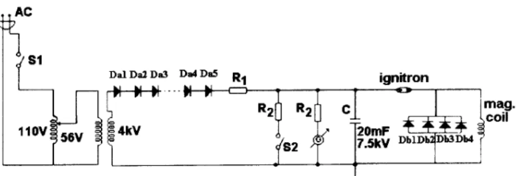
Figure 3. Schematic of the TCABR pellet injector electric circuit.
connected to the high voltage and high current power supply through two regular automotive spark plugs. However, when tested, the commercial spark plugs did not function correc-tly as feed-throughs, and they had to be rebuilt altogether, using more robust materials and choosing a more adequate assembly. Teflon was used as insulator.
4
Power supply
The fast acting valves high current and high voltage power supply was constructed, basically, using diodes, a transfor-mer and a capacitor which was connected to the electric cir-cuit through an ignitron switch (Fig. 3). The power supply was projected as to permit different voltage values to be ap-plied to the transformer through a variac, at the proportion of 90:6400. The secondary of the transformer is connected to the charging circuit which is constituted by 16 rectifying 1N4007 diodes (reverse voltageVR = 1kV, direct current ID= 1A- connected in series), a resistor (R1 = 100kΩ),
to limit the charging current to 50mA, and the capacitor (C = 20mF, VC = 7.5 kV). The valves firing circuit is mainly composed by the ignitron, 4 high current KHP-10 diodes (reverse voltage VR = KHP-10 kV, direct peak current IDP = 2.5kA - connected in parallel) and the encapsulated magnetic coil. When in operation, the voltage used to fire the valve should not exceed the limit of 6.5 = 7.0 kV, to pre-vent the possibility of overloading the capacitor. To measure the electric current flowing through the valves magnetic coil, a Rogowski coil was specifically built, and properly calibra-ted, for this project.
5
System response
To test how the system responds to a capacitor discharge, the constructed Rogowski coil and an integrator, coupled to an oscilloscope, were used to measure the electric current flowing in the coil. In Fig. 4 the temporal current profile ob-tained when a voltage of4kV is applied to the coil is shown. The current duration is typicallyτd ∼200µsand the peak of the current, in this case, isIP ∼4.6kA. During the tests it was observed that the force on the aluminum disk varied considerably in relation to the existing distance between the disk and the top surface of the magnetic coil. The distance
d= 0.5mmwas observed to be the one that yielded the best results without short-circuiting the coil windings during the discharges. The intensity of this force can be calculated ac-cording to the expression [7]:
Fe= πµn2
5500 R2
d2I 2
(2) whereµis the permeability of the medium (polyester resin), nis the number of coil windings,Ris the coil radius andI is the current in the windings.
Figure 4. Typical electric current signal in the coil windings.
´
Alvaro Vannucciet al. 1755
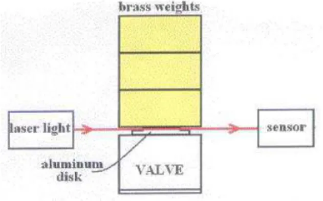
Figure 5. Experimental arrangement idealized to evaluate the val-ves opening time.
Figure 6. Signal obtained using the set-up shown in Figure 5 for a voltage of4.5kV.
6
Conclusion
A fast opening electromagnetic gas valve was built and will be used in the TCABR pellet injector, presently under cons-truction. The valve was projected as to operate under pres-sures that range from 20 to 40 atm at one side of the valve to10−9 atm at the other side. The working principle of
the valve is based on the displacement of an aluminum disk (which controls the gas flux) from its closing position by an electromagnetic force, in result to an induced electric current on the disk caused by a magnetic flux variation. Experimen-tal results showed that the electromagnetic impulse on the disk lasts for 200µsand takes about30msfor the valve to shut up again.
Acknowledgments
The authors want to thank FAPESP - Fundac¸˜ao de Am-paro `a Pesquisa do Estado de S˜ao Paulo for the financial support.
References
[1] S.L. Milora et al. Nucl. Fusion35, 657 (1995).
[2] A. Weeler, A. D. Cheetham, A.W. Edwards et al Phys. Rev. Lett.59, 2303 (1987).
[3] G. Pautasso, K. Bluchl, J.C. Fuchs, et al. Nucl. Fusion36, 1291 (1996).
[4] G. Kocsis et. al Plasma Phys.Control. Fusion41, 881 (1999). [5] B. Gorowitz, K. Moses, and P. Gloersen, Rev. Sci. Instrum.
31, 146 (1960).