I oan Ruja, Elisabeta Spunei, Constantin Marta, I on Piroi, Monica Roşu
Study on the I dentification of an Actuator
The paper presents the results obtained from the study conducted on an execution element in view of its modelling and identification. The mathematical model obtained from the studied execution element con-stitutes the basic information serving to the design of the adjustment algorithm of the automatic system where the actuator will be intr o-duced, as well as the establishment of the technical parameters of the static converter for the supply of the electric motor.
Keyw ords: actuator, identification, transfer function, modelling, indi-cial response
1. I ntroduction
I n order to design the command algorithm of the adjustment system we need to know the mathematical model of the fixed section of the system as well as the calculation method of the regulator in correlation with the specific performances and the technical characteristics of the process.
The execution element subjected to the analysis drives a syringe and is part of the structure of a piece of medical equipment requiring the control of the inject-ing speed of a fluid.
The analytical modelling of an automatic system element, based on the laws of physics, leads to the obtaining of a set of mathematical relations between the inputs / entries and outputs / exits of the studied element.
I n the paper we proceeded to the identification of the non-parametric dy-namic model of the actuator based on the recording of the indicial response.
The experimental results obtained were used through their comparison with the analytical mathematical model of the element resulted from the processing of the transfer functions of each component section of the element.
The experimental identification of the actuat or supposed the completion the following stages [ 1] :
a) Construction and attachment to the actuator of a revolution incremental transducer;
b) Experimental determination of the static characteristic of the execution element;
c) Preparation of the recording / measurement of signals at the entry and exit of the actuator;
d) Establishment of the structure of the actuator model; e) Determination of the model parameters;
f ) Validation of the model.
The knowledge of the automatic system elements by analytical modelling or by identification is currently used by many researchers, and the results of the r e-searches are published in various papers: [ 1] , [ 2] , [ 3] , [ 4] , [ 5] .
2. Theoretical considerations
The actuator is considered to be an element of linear automatic system ob-tained by the interconnection of several mechanical and electrical sub-assemblies. By means of its indicial response we aim at determining the mathematical model in the operational range, as well as the establishment of the parameters intervening in the model.
2.1. Preparation of the signals recording
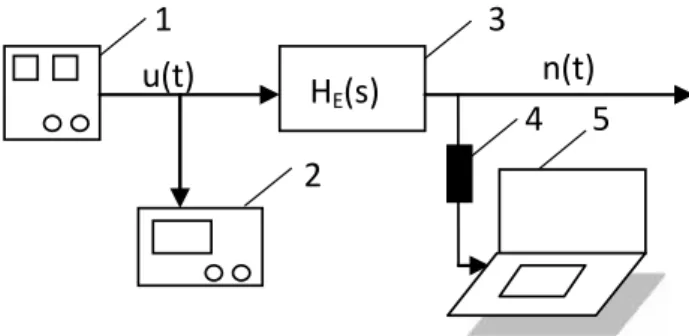
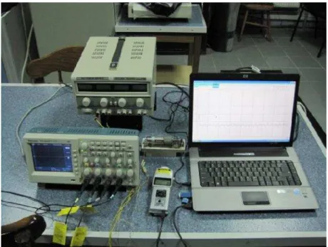
The main diagram of the actuator identification is presented in figure 1.a., where as figure 1.b. shows the experimental installation used by the authors.
Figure 1.a.Diagram related t o the actuator ident ification.
where: 1- electric power supply source; 2- oscilloscope;
3- actuator;
4- revolutions transducer; 5- PC.
The unitary step signal u(t), applied at the entry of the actuator is a voltage signal obtained from a source of variable direct current/ voltage source (u(t)= 15/ 15= 1). The indicial function n(t), the function form the actuator exit, is
1
2
3
5
H
E(s)
u(t)
n(t)
measured with a high-revolution laser digital transducer, without contact. The indi-cial function n(t) is recorded with the help of a PC connected to the transducer through the USB interface.
Figure 1.b.View of the experimental installation.
2.2. Establishment of the model’s structure
The structural diagram of the actuator model is presented in figure 2
Figure 2.Structure diagram of the actuator.
where: H1(s)- transfer function of the static converter;
H2(s)- transfer function of the electric motor;
H3(s)- transfer function of the tachogenerator;
H4(s)- transfer function of a mechanical transmission;
H5(s)- transfer function of incremental transducer.
Fig. 3.Structural diagram of S.R.A.
where: HR(s)- transfer function of the regulator;
HE(s)- transfer function of the electric motor;
HP(s)- transfer function of the process.
The actuator can be considered as being obtained by the series connection of 5 elements of the linear actuator system, each characterised through its own transfer function:
a) the static converter supplying the electric motor with a filtered direct voltage ranging between (0÷ 15) V, with the transfer function H1(s);
b) the direct current motor, with transfer function H2(s);
c) the direct current tachogenerator, with the transfer function H3(s);
d) the mechanical transmission (reducing gear) with the transfer function H4(s);
e) the incremental transducer with the transfer function H5(s).
The analytic modelling allowed the establishment of the expressions of the transfer functions of each element as follows:
a) The modelling of the static converter
The static converter appropriate for the supply of the direct current motor is a four-quadrant one, with the transfer function:
11
1
1
K
H s
T s
, (1)where: K1is the transfer coefficient of the converter;
1
T
is the dead time constant
T
1
f p
; f - frequency of the redressed voltage, f= 50Hz;p - number of pulses of the voltage redressed for a period.
b) Modelling of the electric motor
The direct current electric motor with separate excitation has the transfer function [ 7] :
22 2
1
m e m
K
H
s
T
T s
T
s
where:
K
21
K
is the transfer coefficient of the motor, K being the constant ofthe direct current motor;
2 A m
J R
T
K
is the time constant of mechanical delay, J being the inertiamoment of the parts under rotation motion, RA the resistance of the rotor winding
and of the elements of the direct current motor mounted in series with the former;
A e A
L
T
R
is the time constant of electromagnetic delay, LA being thedis-persion inductivity of the rotor winding.
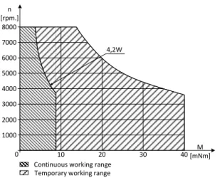
The working range [ 8] of the D.C. motor is presented in figure 4.
0 10 20 30 40
2000 1000 3000 4000 5000 6000 7000 8000 n [rpm.] M [mNm] Continuous working range
Temporary working range 4,2W
Figure 4.Working range of the direct current motor
c) Tachogenerator modelling
The revolution transducers is a direct current tachogenerator with the transfer function [ 9] :
3 3
1
G1
fGK
H
s
T
s
T
s
(3)where:
K
3
K
TG
K
f is the transfer coefficient of the tachogenerator togetherwith the RC philtre at its entry;
fG
T
R C
is the delay time constant of the exit philtre;G
d) Modelling of the mechanical transmission
The mechanical transmission between the direct current motor shaft and sy-ringe is done through two mechanisms connected in series:
- a toothed wheeled reducing gear with the transmission ratio i= 500;
- a screw with bolt transforming the rotation motion (n) into the translation motion (v).
The transfer function of the mechanical transmission is:
4 41
tK
H
s
T s
(4)where:
K
4 is the transfer coefficient of the mechanical transmission;t
T
is the delay time constant of the mechanical transmission.e) Modelling of the incremental transducer
The transfer function of the incremental transducer is:
5 5
H
s
K
(5)The transfer function of the process can be modelled with the relation:
1
p p pK
H
s
T
s
(6)where:
K
p is the transfer coefficient of the process;p
T
is the time constant of the process.The transfer function of the actuator is:
1
2
3
4
5
E
H
s
H s
H
s
H
s
H
s
H
s
(7)
2
1
1
1
1
1
1
E
m m e G fG t
K
H
s
T s
T
s T
T s
T
s
T
s
T s
(8)
where:
K
K K
1
2
K
3
K
4
K
5 are the transfer coefficients of the actua-tor;1
T
,T
m,T
e,T
G,T
fG,T
t are the time constants of the actuator.The sum of the small time constants present in the actuator structure is the following:
1 e G fG t
T
T
T
T
T
T
(9)Thus, the transfer function of the execution element obtained is:
1
1
E
K
H
s
T
s
T s
3. Experimental results and conclusions
3.1. Recording of the indicial response
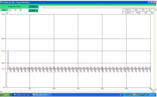
Following the recording of the actuator’s indicial response we obtained the curve presented in figure 5.
Figure 5.I ndicial response in revolution of the actuator.
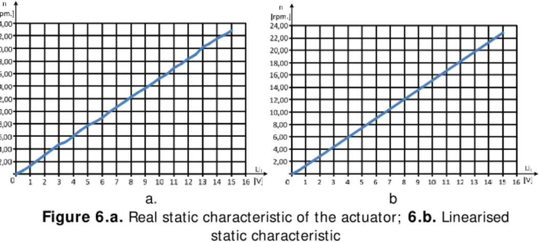
By recording the value of the number of revolutions at the modification of the supply voltage of the actuator Ui we obtained the results presented in table 1
be-low.
Table 1.
Ui[ V] 0.0 0.5 1.0 1.5 2.0 2.5 3.0 3.5 4.0 4.5
n [ r.p.m.] 0 0.6 1.3 2.2 3.0 3.9 4.7 5.2 6.1 6.9
Ui[ V] 5.0 5.5 6.0 6.5 7.0 7.5 8.0 8.5 9.0 9.5
n [ r.p.m.] 7.7 8.3 9.0 9.9 10.7 11.4 12.2 13.0 13.7 14.5 Ui[ V] 10.0 10.5 11.0 11.5 12.0 12.5 13.0 13.5 14.0 15.0
By using these values, we built the real static characteristic of the actuator, shown in figure 6.a., and linearised static characteristic present ed in figure 6.b.
a. b
Figure 6.a.Real static characteristic of the actuator; 6.b.Linearised static characteristic
3.2. Experimental identification
The actuator experimental identification leads to an element of the PT2 type with the following transfer function:
1
1
E
K
H
s
T
s
T s
(11)
where: K is the transfer coefficient; K= 9.56/ 22.9= 0.417
T is the main time constant; T= 10 sec.
TΣis the sum of small time constants present in the actuator structure;
TΣ≈ 0.1 T = 1 sec.
The parameters K, T and TΣresulted form the grapho-analytical processing of
the indicial response curve from figure 5.
3.3. Fixed section of S.R.A
The fixed section of S.R.A. has the transfer function:
1
1
1
f
p
K
H
s
T
s
T s
T
s
(12)
4. Observations and conclusions
Following the study conducted on the execution element the following conclu-sions could be drawn:
4.1 Personal contributions
Construction and attachment to the execution element of a revolution incremental transducer with very small delay moment ( ≈ 0). This transducer allowed the building of the indicial response of the element without introducing additional delays;
Determination of the static characteristic of the element and validation of the linearity hypothesis of the direct current motor;
Establishment of the transfer function of the execution element and determination of the parameters based on the indicial response;
I nterpretation of results.
4.2 Conclusions
The execution element respects the characteristic of a linear system element obtained by assembling several simpler system elements (di-rect current motor, D.C. tachogenerator, mechanical reducing gear). The experimental results obtained by measurements (static character-istic) validate the hypothesis of linearity made at the analyt ical study of the elements and the establishment of the transfer function, valid for linear elements;
The indicial response in revolution indicates a PT2 element, in critical damped regime, which is indicated for medicine applications;
Determination of the parameters from the mathematical model in op-erational based on the indicial response allows the synthesis of an ad-justment system, as well as the establishment of the accord param e-ters of regulators;
The analysed execution element corresponds to an element able to ensure a good rapidity / safety in exploitation ratio.
References
[ 1] Landeu I .D., I dentification and command of systems(in Romanian), Didactic and Pedagogic Publishing House R.A., Bucharest, 1993.
[ 2] Smeets J.P.C, Overboom T.T., Jansen J.W., Lomonova E.A., Modelling Framework for Controllers Energy Transfer Systems for Linear Actuators, I EEE Transaction on I ndustrial Electronics, vol.60, no.1, p.391-399, 2013.
High-Efficiency Rectifier, I EEE Transaction on I ndustrial Electronics, vol. 60, no.1, p.280-289, 2013.
[ 4] Musolino V., Piegani L., Tironi E., New Full-Frequency Range Supercapacitor Model with Easy I dentification Procedure, I EEE Transaction on I ndustrial Elec-tronics, vol.60, no.1, p.112-120, 2013.
[ 5] Chengbin Ma, Juny Cao, Zue Qiao.,Polynomial-Method-Based design of Low-Order Controllers for Two-Mars System, I EEE Transaction on I ndustrial Elec-tronics, vol.60, no.3, p.969-978, 2013.
[ 6] Vandoern T.L., I onescu M.C., de Koonlug J.D.M., de Keyser R., Vandevelde L., Theoretical Analysis and Experimental Validation of Single-Phase Direct ver-sus Cascade Voltage Controll in I slanded Microgrids, I EEE Transaction on I n-dustrial Electronics, vol.60, no.2, p.789-798, 2013.
[ 7] Tunsoiu Gh., Seracin E., Saal C., Electric Drives (in Romanian), Didactic and Pedagogic Publishing House R.A., Bucharest, 1982.
[ 8] * * * * * Cataloque PORTESCAP,http:/ / manubatbat.free.fr/ .
[ 9] Dumitrache I ., Dumitria S., Mihu I ., Munteanu F., Muscă GH., Colcev C.,
Electronic Automation (in Romanian), Didactic and Pedagogic Publishing House R.A., Bucharest, 1993.
Addresses:
Prof. Dr. Eng. I oan Ruja, “ Eftimie Murgu” University of Reşiţ a, Piaţ a Traian Vuia, nr. 1-4, 320085, Reşiţ a, [email protected]
Lecturer. Dr. Eng. Elisabeta Spunei, “Eftimie Murgu” University of Reşiţ a, Piaţ a Traian Vuia, nr. 1-4, 320085, Reşiţ a, [email protected]
Prof. Dr. Eng. Constantin Marta, “Eftimie Murgu” University of Reşiţ a, Piaţ a Traian Vuia, nr. 1-4, 320085, Reşiţ a, [email protected]
Prof. Dr. Eng. I on Piroi, “ Eftimie Murgu” University of Reşiţ a, Piaţ a Traian Vuia, nr. 1-4, 320085, Reşiţ a, [email protected]