M. Papadrakakis, V. Papadopoulos, G. Stefanou, V. Plevris (eds.) Crete Island, Greece, 5–10 June 2016
COMPUTATIONAL MODELLING OF COLD-FORMED STEEL
SCREWED CONNECTIONS AT AMBIENT AND ELEVATED
TEMPERATURES
Luís Mesquita1, Rui Dias2, Armandino Parente2 and Paulo Piloto3 1 ISISE, Polytechnic Institute of Braganca
Campus de Santa Apolónia, 5300-253 Bragança, Portugal [email protected]
2 Polytechnic Institute of Braganca
Campus de Santa Apolónia, 5300-253 Bragança,, Portugal {rui_paulinho_93, armandino_parente}@hotmail.com
3 LAETA-Inegi Polytechnic Institute of Braganca
Campus de Santa Apolónia, 5300-253 Bragança,, Portugal
Keywords: Screwed connections, Cold-formed steel sheet, Elevated temperatures, Experi-mental tests, Finite element modelling.
Abstract. The application of cold-formed steel structural members in steel construction, and in particular building construction, has a number of advantages that includes its high structural efficiency compared to the member weight. In recent years the increasing safety requirements reflected in the different design standards, boosted the behaviour of materials under extreme conditions, in particular in conditions of high temperatures such as those arising from fires.
This work presents a study of the behaviour of cold-formed thin steel sheeting screwed connec-tions at room temperature and elevated temperatures. The shear and bearing failure modes are analysed experimentally by means of a parametric analysis, considering: (i) different elevated temperature values; (ii) cold-formed steel grades; (iii) board effect of the screw position; (iv) and different steel sheet thicknesses. The set of experimental results are used for calibration and verification of the numerical model developed by the finite element method in the software Ansys.
1 INTRODUCTION
The application of cold-formed steel structural members in steel construction, and in partic-ular building construction, has a number of advantages that includes its high structural effi-ciency compared to the member weight. These sections are usually obtained by thin cold-formed sheets and have slender cross-sections. Although the member resistance is affected by local and distortional buckling instability phenomena, one can reduce these effects by local restraints to the partition walls panels or the building envelop panels, by means of self-drilling or self-tapping screws. Additionally the building erection phase is faster due to the ease steel-to-steel connection between structural members by means of self-drilling screws.
In recent years the increasing safety requirements reflected in the different design standards, boosted the behaviour of materials under extreme conditions, in particular in conditions of high temperatures such as those arising from fires.
The design of cold-formed sections and their connection elements must be performed at room temperature and also in an accidental fire situation, for which the connection strength design value must be determined at elevated temperatures. At room temperature, bolted shear connections from bearing type category must be verified against shear and bearing failure modes. This methodology differs from that presented in EN1993-1- 3, which provides the de-sign resistances of connections for cold-formed members and sheeting. At elevated tempera-tures the Annex D from EN 1993-1-2 specifies the fire design resistance of bolts loaded in shear as a function of its ambient temperature resistance (from EN1993-1-8) and a reduction factor determined for the appropriate bolt temperature.
In the case of thin steel sheets with thicknesses that typically vary between 0.5 and 3 [mm] screwed connections of these elements are carried out with self-drilling screws without the need of opening a hole, as is shown in Figure 1.
Figure 1 - Self-drilling screws in cold formed profiles.
These screwed connections behave differently than the conventional bolted connections. In the case of self-drilling screwed connections of thin steel sheets, the joint collapse load is usu-ally determined by the bearing resistance of the plates, and only in thicker plates by the screw shear resistance. This distinction is even more noticeable in the case of structures under fire conditions. The heating rate of the thin sheets is higher than the heating rated of the screws, due to their higher thermal capacitance. Therefore, with the increase of temperature, the decrease of the bearing resistance is higher than the screw shear resistance, and may lead to a change of the collapse mode at ambient temperature.
the influence of the bolt diameter. In addition to the test temperature and the sheets thickness, they studied the influence of one and two bolts with different positions and different bolt diam-eters. The results show four failure modes: namely the bolt shear, bearing, tear out and net section failure.
Lu et al conducted an experimental and numeric study on screwed connections at different temperature levels: 20ºC, 200ºC, 400ºC e 600ºC. The results show two types of failure: (i) thin sheet bearing failure for tests under 200ºC and (ii) screw shear failure for tests at 400ºC and 600ºC. From this results, the authors proposed a design formula based on the EC3-1-8 rules, when the ratio between the distance of the hole to end and the diameter of the hole is between
1.00-1.75 (1.00 ≤ e2⁄d ≤ 1.75), [3]. The same authors also performed a numerical study of the
connections using the finite element method in Abaqus software, considering an non-linear ex-plicit analysis, [4]. The simulations consider the material and geometry nonlinearity and contact elements between the various surfaces. The bolt geometry is simplified by a simulated thread with three circumferential segments.
Chung and IP conducted a numeric study on thin sheet steel connections, form G300 and G550 sheets, using the finite element software Ansys, [5]. The numerical analyses include the elastoplastic behaviour of the material obtained experimentally and contact elements with a friction coefficient equal to 0.2. The numerical results show that the contact stiffness and fric-tional coefficient between element interfaces, and clamping force in bolt shanks are important parameters for accurate prediction of bolted connections load-displacement behaviour.
This work presents a study of the behaviour of cold-formed thin steel sheeting screwed connections at room temperature and elevated temperatures. The shear and bearing failure modes are analysed experimentally by means of a parametric analysis, considering: (i) dif-ferent elevated temperature values; (ii) cold-formed steel grades; (iii) board effect of the screw position; (iv) and different steel sheet thicknesses. The set of experimental results are used for calibration and verification of the numerical model developed by the finite element method in the software Ansys. The numerical method is used for a wider parametric analysis about cold-formed screwed connections at elevated temperatures. The numerical and exper-imental results are compared with the simplified calculation method presented in the Euro-pean standards.
2 SAFETY VERIFICATION OF BOLTED CONNECTIONS
The design of screwed connections must be performed at room temperature and also in an accidental fire situation, in which it is necessary to know the resistance design value in function of exposure temperature. At room temperature the bolted connections loaded in shear of the bearing type, according to EN1993-1-8, should comply with the safety verifications in relation to their design shear resistance and design bearing resistance. This methodology differs from the one presented in the EN1993-1- 3 for cold-formed member connections, which provides rules for the design of self-drilling screwed connections. At elevated temperatures, the annex D of EN1993-1-2 presents the methodology to design bolted connections for shear and bearing resistance, updating the ambient temperature design resistance by a reduction factor for the appropriate bolt temperature.
2.1Design of bolted connections at ambient temperature.
The design methodology of bolted connections in shear, defined as category A according to EC3 part 1.8, [6], stats that the design ultimate shear load should not exceed the design shear
2 rd
v,
M ub vf A F (1) 2 1 d , M u b R b dt f k F (2)
Where v represents the factor associated with the bolt class (v= 0.6 for classes 4.6, 5.6 e
8.8, v= 0.5 for classes 4.8, 5.8 e 10.9). If the shear plane passes through the threaded part of
the bolt is assumed v= 0.6, fubrepresents the bolt ultimate of tensile strength, A the resistant
area of the bolt and M2 the partial safety factor for joints. The constant b is obtained by the
smallest of fub /fu , αd or 1. The value of αd must be calculated for end bolts and inner bolts
independently, by the following expressions, respectively:
0 1 d 3d e (3) 4 1 3 0 1 d
d p
(4)
The factor k1 considers the bolt position perpendicular to the direction of load transfer. For
edge bolts assume the smallest of equations (5) and (6) values and 2.5. In the case of inner bolts k1 is given by the smallest value between the equation (6) and 2.5.
7 . 1 8 . 2 0 2 d e (5) 7 . 1 4 . 1 0 2 d p (6)
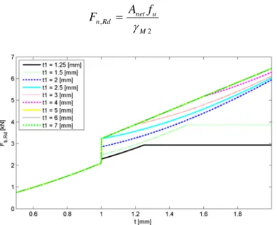
Eurocode 3 part 1-3, [7], provides additional rules for safety verification of cold-formed thin steel sheets screwed connections (applied to self-drilling screws). In this case the connections bearing resistance is determined by the following equation.
2 , M u Rd b dt f F (7)
The value of α is determined in function of the thickness of the connected plates, by the following expressions. 1 1 . 2 2 .
3 for t t
d
t
(8) mm t and t t for d
t 2.1 2.5 1.0
2 .
3 1
(9) mm t and t t
for 2.5 1.0
1 .
2 1
(10)
represents the thickness of the thinner plate and 1 the thickness of thicker plate. In the
cases not mentioned, α is obtained by interpolation (tt12.5t). The net section resistance is
2 ,
M u net Rd n
f A F
(11)
Figure 2 - Bearing resistance according to EN1993-1-3 for different steel sheet thicknesses.
Additionally, it is necessary to check the screw shear resistance. However, this part of the Eurocode defines that this resistance is determined through experimental testing, dividing the
characteristic shear resistance (Fv,Rk) by the partial safety factor. This experimentally
deter-mined value, in the case of a single screw connection, is subject to the conditions presented in equation 13.
2 , ,
M Rk v Rd v
F F
(12)
Rd b Rd
v F
F, 1.2 , or Fv,Rd 1.2Fn,Rd (13)
The experimental values are usually determined through experimental tests conducted by the screw manufacturers when the product certification is based on an European technical approval (ETA). In the case of the screws used in this study, the shear resistance characteristic values, at room temperature, are presented by SFS INTEC in ETA-10/0198 [8].
2.2Design of screwed connections at elevated temperatures.
The annex D of EN 1993-1-2, [9], presents the methodology to determine the resistance of screwed connections in shear and bearing at at elevated temperatures. The net-section failure at screw holes do not need to be considered if there is a screw in each hole, because the steel temperature is lower at the connection due to the presence of additional material. The shear and
bearing resistances are determined by the following equations, in which Fv,Rd and Fb,Rd are
rel-ative to the screw resistance at room temperature.
, , , , , (14)
, , , , , (15)
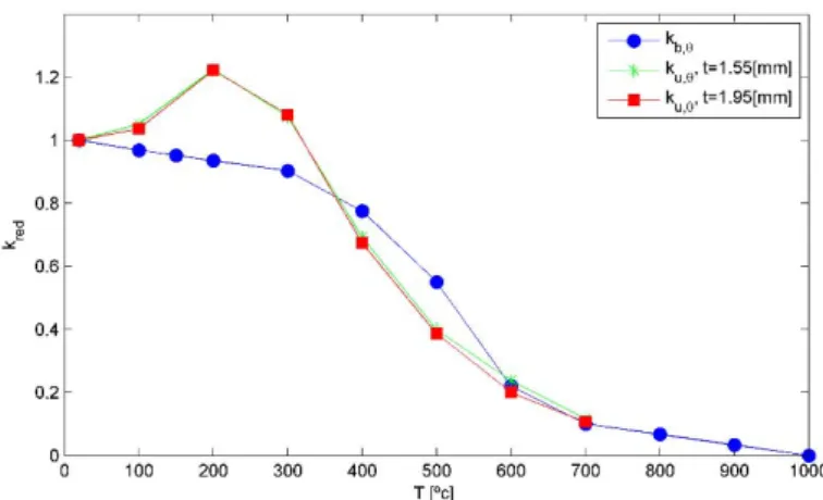
, represents the reduction coefficient for the appropriate screw temperature. This
and its comparison with the ultimate strength ( , reduction coefficient for the material G250,
with , . 292 and 361 , determined by Kankanamge et al [10]. The next
fig-ure shows that in temperatfig-ure range 400-600 [ºC] the reduction coefficient , increases the
bearing resistance in a non-conservative way.
Figure 3 - Bearing resistance reduction value and comparison with the G250 ultimate strength temperature varia-tion. [10].
3 EXPERIMENTAL TESTS
3.1Thin steel sheets screwed connections.
This paper presents a set of experimental tests at elevated temperatures on the behaviour of screwed connections of thin steel sheets in simple shear. The galvanized steel sheets are from
class DX51D +Z (EN10342) with fy 284
MPa
and fu 355
MPa
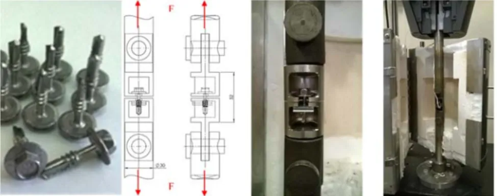
. The connections aremade with self-drilling carbon steel screws, with the reference SFS SD6-H15 Ø5,5 x 22 mm and a diameter of D=5,5 [mm]. The screw is placed along the middle axis of the sheet and the different distances from the end edge to the hole centre (e1): 10mm, 15mm and 20mm, as pre-sented in Figure 4. A parametric study is made considering the steel sheets thickness (1.5+1.5, 2.0+1.5 and 2.0+2.0 [mm]) and different temperature levels, representative of a fire event.
The tests presented allow the analysis of this parameters on the connection resistance and on the collapse mode.
Figure 4 - Dimensions of test specimens for the screwed connections.
Figure 5 - Experimental setup of the screwed connections.
The experimental setup consists of a universal tensile testing machine to apply the mechan-ical load, (Figure 5), resulting in a shear effort to the screw. The elements are placed inside of an electric furnace, whose temperature is measured by the thermocouple type K and controlled by a PID system. After the set point temperature is attained, and a small initial load of approx-imately 0.1 [KN] is applied, the test starts with a displacement control at the velocity equal to 1 [mm/min], following the reference to the technical documentation of the ECCS, [11]. Ac-cording to this procedure, the failure resistance must be defined as the peak load in a defor-mation of 3[mm], as represented in Figure 6, using an extensometer in a reference length of 150 [mm]. To measure the reference length extension two auxiliary rods, fixed to steel plates are used, allowing the mechanical extensometer be placed outside the furnace, as can be seen in Figure 5.
Figure 6 – Experimental tests failure limits, [11].
The failure modes obtained from self-drilling screwed connections are usually one or a com-bination of two failure modes presented in Figure 7. This figure presents the mechanisms of failure by shearing of the screw (SFM), bearing failure mode (BFM), which can occur with or without tearing of the steel sheet, and screw pull-out and tilting due to the screw slipping from the connection hole (TFM). In the case of thick steel sheets the expected failure mode is due to the screw shear, while for very thin steel sheets the sheet tearing or bearing is verified. Other situations may include two or more combinations of this failure modes.
Figure 7 - Failure modes: Shear failure mode (SFM), b) Bearing failure mode (BFM), c) Tilting failure mode (TFM).
Varão Inconel 600
=30[mm]
e1
50 [mm]
L=150
[mm
]
e1
e1
25
F
F
Rmax
d
3 [mm] 3 [mm] d
Figure 8 presents the experimental results for a combination of sheet thicknesses 1.5+1.5 [mm], considering the applied load in function of the displacement, for different edge distances of the connection and temperature values.
Figure 8 - Experimental results of plates 1.5+1.5 [mm] at a temperature of 20, 200, 400, 500, 600 e 800 [ºC].
In the Table 1 the experimental tests results are presented for the maximum load, the load value for 3 [mm] displacement and the failure mode or combination of modes visualized in each test. The table also present the resistance of each connection determined from the simplified equations EC3-1-8 and EC3-1-3, presented in the previous section, considering unit partial safety factors.
The results show that, as expected, the connection resistance decreases with the temperature increase, with the exception of the 200 [ºC] tests, requiring some additional tests. For the same sheet combination, 1.5+1.5 or 2.0+1.5, the resistance increases with the edge distance e1, inde-pendently of the test temperature. However, the table shows that the failure mode is mostly influenced by the edge distance (e1) and the test temperature. For thinner steel sheets (1.5+1.5), when an edge distance e1=10[mm] is used, the failure mode is always due to bearing, while for e1=20 [mm] the most predominant is the tilting failure mode, where the screw rotation and sliding is attained. For the combination of steel sheets 2.0+1.5 with an edge distance e1=20[mm] the predominant failure mode is due to the screw shear, with the exception of the room temper-ature tests. For steel sheet thicknesses 2.0+2.0 at a tempertemper-ature of 500[ºC], the failure mode is always do to shear, regardless of the edge distance value.
3.2Mechanical strength of the screws steel
EN10263. The threaded length is opened by cold working followed by a hardening heat treat-ment and stress relief. Finally, there is a surface treattreat-ment and dehydrogenation.
According to the manufacturer's experimental tests of the screws, the bolt tension resistant and shear resistance are 16 and 10 [KN], respectively, [13].
Reference PMAX
[kN] P[d=3mm] [kN] Failure mode EC3-1-8 EC3-1-3 Fb,t,Rd Fv,t,Rd Fb,t,Rd Fv,t,Rd
P1.5+1.5_1.82d_T20 5.820 5.514 BFM 4.438 6.808 4.894 3.430
P1.5+1.5_1.82d_T200 6.008 5.659 BFM 5.432 8.332 5.991 4.198
P1.5+1.5_1.82d_T400 4.537 4.435 BFM 3.075 4.718 3.392 2.377
P1.5+1.5_1.82d_T500 2.336 2.303 BFM 1.771 2.716 1.953 1.369
P1.5+1.5_1.82d_T600 1.622 1.616 BFM+TFM 1.052 1.613 1.160 0.813
P1.5+1.5_2.73d_T20 6.459 6.266 TFM+SFM 6.656 6.808 4.894 3.430
P1.5+1.5_2.73d_T200 6.260 5.686 BFM 8.147 8.332 5.991 4.198
P1.5+1.5_2.73d_T400 4.387 3.871 TFM 4.613 4.718 3.392 2.377
P1.5+1.5_2.73d_T500 3.141 2.964 TFM 2.656 2.716 1.953 1.369
P1.5+1.5_2.73d_T600 2.223 1.777 SFM 1.578 1.613 1.160 0.813
P1.5+1.5_3.64d_T20 7.152 6.051 TFM 7.322 6.808 4.894 3.430
P1.5+1.5_3.64d_T200 6.765 6.003 TFM 8.962 8.332 5.991 4.198
P1.5+1.5_3.64d_T400 5.004 4.999 TFM 5.074 4.718 3.392 2.377
P1.5+1.5_3.64d_T500 3.281 3.125 TFM 2.921 2.716 1.953 1.369
P1.5+1.5_3.64d_T600 2.266 1.766 SFM 1.735 1.613 1.160 0.813
P2.0+1.5_1.82d_T20 5.750 5.101 BFM 4.438 6.808 5.173 4.310
P2.0+1.5_1.82d_T200 6.631 6.325 BFM 5.432 8.332 6.332 5.275
P2.0+1.5_1.82d_T400 4.977 4.940 BFM 3.075 4.718 3.585 2.987
P2.0+1.5_1.82d_T500 3.001 2.996 BFM 1.771 2.716 2.064 1.720
P2.0+1.5_1.82d_T600 1.670 1.664 BFM+SFM 1.052 1.613 1.226 1.021
P2.0+1.5_2.73d_T20 8.086 6.636 SFM 6.656 6.808 5.173 4.310
P2.0+1.5_2.73d_T200 8.666 7.452 SFM 8.147 8.332 6.332 5.275
P2.0+1.5_2.73d_T400 5.702 5.380 TFM+SFM 4.613 4.718 3.585 2.987
P2.0+1.5_2.73d_T500 3.511 3.485 TFM+SFM 2.656 2.716 2.064 1.720
P2.0+1.5_2.73d_T600 1.863 1.788 TFM+SFM 1.578 1.613 1.226 1.021
P2.0+1.5_3.64d _T20 8.274 6.481 TFM 7.322 6.808 5.173 4.310
P2.0+1.5_3.64d _T200 7.501 7.114 SFM 8.962 8.332 6.332 5.275
P2.0+1.5_3.64d _T400 4.730 4.515 TFM+SFM 5.074 4.718 3.585 2.987
P2.0+1.5_3.64d _T500 3.458 3.426 TFM+SFM 2.921 2.716 2.064 1.720
P2.0+1.5_3.64d _T600 1.885 1.681 TFM+SFM 1.735 1.613 1.226 1.021
P1.5+1.5_1.82d_T800 0.397 0.344 BFM 0.186 0.285 0.205 0.144
P1.5+1.5_2.73d_T800 0.537 0.526 TFM 0.279 0.285 0.205 0.144
P1.5+1.5_3.64d_T800 0.532 0.532 TFM 0.307 0.285 0.205 0.144
P2.0+2.0_1.82d_T20 8.059 6.196 SFM 5.917 6.808 7.535 4.310
P2.0+2.0_2.73d_T20 8.977 5.981 SFM 8.875 6.808 7.535 4.310
P2.0+2.0_3.64d_T20 9.364 7.060 SFM 9.763 6.808 7.535 4.310
P2.0+2.0_1.82d_T500 3.474 3.474 SFM 2.361 2.716 3.007 1.720
P2.0+2.0_2.73d_T500 3.640 3.452 SFM 3.541 2.716 3.007 1.720
P2.0+2.0_3.64d_T500 3.839 3.650 SFM 3.895 2.716 3.007 1.720
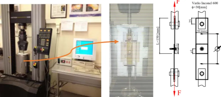
With the aim of establish the classification of the screw material strength, a set of tensile experimental tests were carried out until the material rupture, using a universal testing machine. The screws were previously machined to remove the threads and to create a constant reference length with 6 [mm] of length and 3 [mm] of diameter. An increasing load was applied to the screw between its head and a drilled 4 [mm] thick sheet, as shown in Figure 9. For the tests performed at elevated temperatures this setup was placed inside an electric ceramic furnace.
Figure 9 - Experimental setup for traction test.
Table 2 presents the average values of the experimental results of maximum load and its tensile strength for different temperature levels. The results show a noticeable reduction of the screw ultimate strength with temperature. The average results at room temperature (from a set of three) allow us to conclude that the screw meets the requirements of the minimum tensile strength for the class 10.9.
Temp. [ºC] PMAX [kN] Ultimate Strength [Mpa]
20 8,003 1135,67
200 7,952 1125,00
400 5,326 753,50
500 3,157 443,9
Table 2 – Average value of the screws tensile tests.
4 NUMERICAL MODELLING OF THIN SHEET SCREWED CONNECTIONS
Figure 10 - Geometric model used in the numerical simulations.
In the case of thin steel sheets, being considered of class 4, the design yield strength and its variation with temperature must be considered equal to the proportional limit strength at 0.2% deformation. For this class the temperature reduction coefficients of yield stress at 2% are not presented. This requires a modification of stress-strain curves design presented by Eurocode 3 part 1-2, consisting in an iterative process for calculating the 2% reduction coefficients, and its yield strength in function of the temperature, so that the proportional limit strength at 0.2% match the ones from EN1993-1-2 annex E, [9].
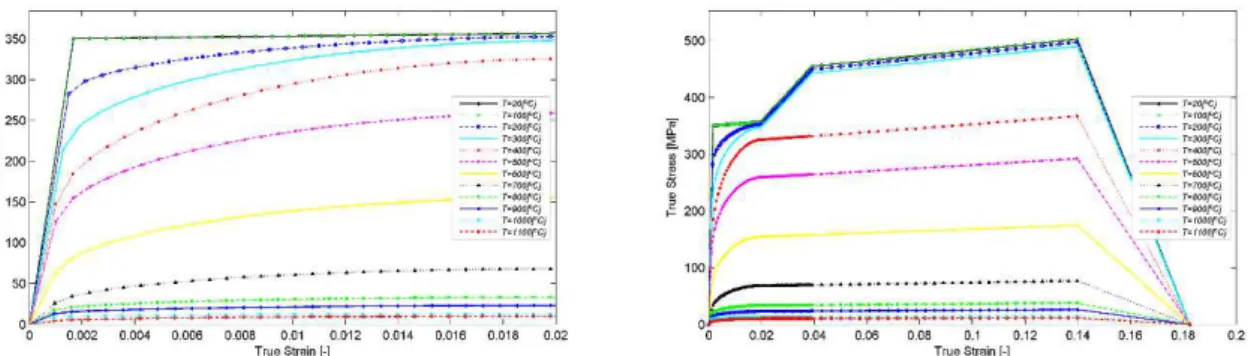
The nonlinear material analysis performed in Ansys defined by an elastic-plastic material law, needs the stress-strain curves to be converted into true stress-true strain curves. This trans-formation is accomplished by the following equations, where the nominal stresses and strain values are determined by the nominal curves provided by EC3-1-2.
1
1 (16)
The Figure 11 presents the true stress-strain curves for different temperature values of gal-vanized steel sheets S350GD + Z, with a yield stress at 0.2% equal to 350 [MPa], and consid-ering strain hardening up to 400 [ºC].
Figure 11 - True stress-strain curves for different temperatures.
As this self-drilling screws are not classified as the conventional bolts, to allow the material characterization a set of tensile tests were done to the screws in tension. The average ultimate strength value obtained was 1135.67 [MPa], allowing the screw to be classified as class 10.9, from ISO898-1:1999 [12]. The screw material stress strain curves follow a bilinear model de-fined by the yield strength and a tangent modulus equal to E/100.
4.1Numerical simulations.
determined, this was not included in the numerical analysis. The second step consists in apply-ing a linearly increasapply-ing load, with minimum increments of 1 [N], while the equilibrium condi-tion are attained, obtaining the conneccondi-tion collapse load at the end of the simulacondi-tion.
Figure 12 presents the finite element model of two thin steel sheets (1+2 [mm]) screwed connection considering an edge distance equal to 20 [mm]. To reduce the finite element model and its computational time a symmetry condition was used. The Von Mises equivalent stress distribution show the yielding of the sheets due to bearing, with stress values higher than the yield stress, and a small plastic area along the screw thread, with stresses over 900 [MPa]. The connection collapse load applied at this instant is 4693.4 [N]. The numerical results from sim-ulations performed with a steel sheets combination equal to 2+2 [mm] allow to obtain a collapse load of 5600 [N].
Figure 12 - Finite element model of steel sheets 2+1 [mm]. Steel sheets and screw von Mises equivalent stress distribution at the collapse load.
5 CONCLUSIONS
The experimental tests presented allowed to determine the load resistance of self-drilling
screwed connections of thin steel sheets and the influence of the sheet thickness, edge dis-tance (e1) and the connection temperature.
For the same connection, keeping the sheet thickness and edge distance e1, we can observe
a change on the failure mode with the temperature increase. The three failure modes were detected, being mainly the screw shear failure, steel sheets bearing failure and a combina-tion of both.
Connections with double steel sheets of 2.0 [mm] have a failure mode due to screw shear
at ambient temperature and at 500 [ºC]. Connections with double steel sheets of 1.5 [mm], the failure mode varies with the edge distance e1 and changes from steel sheets bearing failure to a combination of tilting and screw shearing at higher temperatures.
The finite element numerical model shown allow to study the behaviour of self-drilling
screwed connections and determine the collapse load. The cases analysed give results close to the characteristic resistance of the screws manufacturer.
Further experimental tests are being planned for a parametric analysis of the steel sheet
ACKNOWLEDGEMENTS
The authors acknowledge the support and the supply of materials used in the study from the companies SFS INTEC, LUSOSIDER and IRMALEX.
REFERENCES
[1] Yan, S. and B. Young, Tests of single shear bolted connections of thin sheet steels at
elevated temperatures—Part I: Steady state tests. Thin-Walled Structures, 2011. 49(10):
p. 1320-1333.
[2] Yan, S. and B. Young, Tests of single shear bolted connections of thin sheet steels at elevated temperatures—Part II: Transient state tests. Thin-Walled Structures, 2011.
49(10): p. 1334-1340.
[3] Lu, W., et al., Design of screwed steel sheeting connection at ambient and elevated
temperatures. Thin-Walled Structures, 2011. 49(12): p. 1526-1533.
[4] Lu, W., et al., Behaviour of shear connectors in cold-formed steel sheeting at ambient and
elevated temperatures. Thin-Walled Structures, 2012. 61: p. 229-238.
[5] Chung, K.F. and K.H. Ip, Finite element modeling of bolted connections between cold-formed steel strips and hot rolled steel plates under static shear loading. Engineering
Structures, 2000. 22(10): p. 1271-1284.
[6] Portugal. Instituto Português da Qualidade, Eurocódigo 3 projecto de estruturas de aço Parte 1-8 projecto de ligações NP EN 1993-1-8: 2010. 2010, Caparica: IPQ. 146 p. [7] CEN, EN1993-1-3 Eurocode 3 : Design of steel structures, Part 1-3: General rules
Supplementary rules for cold-formed members and sheeting. 2004, European Committee for Standardization: Brussels, Belgium.
[8] EOTA, ETA-10/0198 Fastening screws for metal members and sheeting, Fastening screws SFS, SFS intec AG. 2013: European Organisation for Technical Approvals. [9] IPQ, Eurocódigo 3 projecto de estruturas de aço Parte 1-2 regras gerais. Verificação da
resistência ao fogo NP EN 1993-1-2: 2010, ed. Instituto Português da Qualidade. 2010, Caparica: IPQ. 87 p.
[10] Kankanamge, N.D. and M. Mahendran, Mechanical properties of cold-formed steels at
elevated temperatures. Thin-Walled Structures, 2011. 49(1): p. 26-44.
[11] ECCS-TC7, ECCS TC 7: The Testing of Connections with Mechanical Fasteners in Steel Sheeting and Sections. Vol. Nº 124. 2009, Brussels: Brussels.
[12] Standardization, E.C.f., EN ISO 898-1:1999 - Mechanical properties of fasteners made of carbon steel and alloy steel - Part 1: Bolts, screws and studs. 1999.

![Figure 8 presents the experimental results for a combination of sheet thicknesses 1.5+1.5 [mm], considering the applied load in function of the displacement, for different edge distances of the connection and temperature values](https://thumb-eu.123doks.com/thumbv2/123dok_br/16865776.753980/8.892.157.744.234.581/experimental-combination-thicknesses-considering-displacement-different-connection-temperature.webp)
![Figure 12 presents the finite element model of two thin steel sheets (1+2 [mm]) screwed connection considering an edge distance equal to 20 [mm]](https://thumb-eu.123doks.com/thumbv2/123dok_br/16865776.753980/12.892.167.728.345.688/figure-presents-finite-element-screwed-connection-considering-distance.webp)