António Manuel de Almeida Campos
Framework para aplicações de
monitorização de Sistemas Embebidos,
Web based e Open-Source
Ant
ónio Manuel de Almeida Cam
pos
F
rame
w
or
k para aplicações de monitor
ização de Sis temas Embebidos, W eb based e Open-Sour ce
Universidade do Minho
Escola de Engenharia
Tese de Mestrado
Ciclo de Estudos Integrados Conducentes ao Grau de
Mestre em Engenharia Eletrónica Industrial e Computadores
Trabalho efetuado sob a orientação do
Professor Doutor Paulo Cardoso
António Manuel de Almeida Campos
Framework para aplicações de
monitorização de Sistemas Embebidos,
Web based e Open-Source
Universidade do Minho
To my mother and father Labor Omnia Vincit
FRAMEWORK FOR EMBEDDED SYSTEMS MONITORING APPLICATIONS, WEB-BASED AND OPEN-SOURCE
by
Ant´onio Campos
DISSERTATION
Presented to the Faculty of the School of Engineering of the University of Minho in Partial Fulfillment of the Requirements for the Degree of Master of Science,
under the supervision of Professor Paulo Cardoso.
Department of Industrial Electronics University of Minho
Acknowledgements
First of all, I’d like to thank professor Paulo Cardoso for being my advisor, for giving me the independence to work and, most of all, for questioning the whys and the why nots of my work. ”From now on our relationship is between co-workers! I will not demand anything from you, this is your work. I will discuss it with you!”.
I’d also like to thank to the professors and technicians of the Industrial Electronics Department. Even though you imposed many challenges that gave me a lot of headaches and even made me sweat, I am now ready to face the real world. Also, to all the teachers that came in my path since 1994, you all taught me something and established the base for me to be here now.
I would also like to thank my parents, Celso and Nat´alia. You both gave me the strength to
continue, to always accomplish more, to not be afraid of whatever may come my way. Without you I wouldn’t be here today! Thank you mom! Thank you dad! (One down, one to go!)
To Liliana, my sister, for the nagging. Now that you are where I was a few years ago, enjoy it to the fullest, you can go wherever you want to!
To Marta, my girlfriend. You appeared in the beginning and in the end, in a time where everything was going downhill and somehow you managed to help me getting back on track. ”Get out of bed, you have got to work!”
To Susana, for making me get on track five years ago and for the sharing.
To all my brothers from other mothers, for being with me all these years. For the adventures we had together, for the long nights studying, for the jokes, for the brotherhood and most of all for being my friends.
Resumo
Monitorizar consiste em observar, supervisionar ou controlar um sistema. Como tal, todas as
aplica¸c˜oes de monitoriza¸c˜ao desempenham uma fun¸c˜ao semelhante em sistemas diferentes. Sendo
assim, pode dizer-se que todas as aplica¸c˜oes de monitoriza¸c˜ao s˜ao desenvolvidas sobre uma base
comum, uma vez que a tarefa a desempenhar ´e semelhante, sendo os dados diferentes entre
aplica¸c˜oes. Pode assumir-se ent˜ao, que desenvolver uma aplica¸c˜ao deste tipo de raiz consome
mais recursos que o necess´ario.
Existem muitos sistemas embebidos que necessitam de monitoriza¸c˜ao, alguns tˆem at´e o acesso
f´ısico restringido, criando a necessidade de monitoriza¸c˜ao remota. Este projecto tem como
ob-jectivo responder a esta necessidade atrav´es da cria¸c˜ao de uma ferramenta capaz de implementar
aplica¸c˜oes de monitoriza¸c˜ao remota que utilizem a Web como meio de comunica¸c˜ao, fornecendo
uma arquitectura para que sistemas embebidos possam comunicar com o utilizador atrav´es da
Web.
O Desenvolvimento de Software Orientado a Caracter´ısticas (FOSD) ´e utilizado como m´etodo
de desenvolvimento nesta ferramenta, permitino o desenvolvimento de uma Linha de Produ¸c˜ao
de Software (SPL) para o dom´ınio de monitoriza¸c˜ao remota de sistemas embebidos.
O resultado deste trabalho ´e uma SPL capaz de implementar aplica¸c˜oes de monitoriza¸c˜ao
remota constitu´ıdas por um interface do utilizador, um interface com a plataforma, uma base de
dados e um conjunto de servi¸cos Web que estabelecem um daemon de comunica¸c˜ao, de forma
simples atrav´es da utiliza¸c˜ao do plug-in para o Eclipse, Feature IDE.
Esta solu¸c˜ao facilita o processo de desenvolvimento e reduz drasticamente o time-to-market
de uma aplica¸c˜ao de monitoriza¸c˜ao espec´ıfica. Utiliza tamb´em os conceitos FOSD e SPL, que
Abstract
Monitoring consists on observing, supervising or controlling a system. Therefore, all monitoring applications carry a similar task, only in different systems. Knowing this, one can easily say that monitoring applications are built upon the same base, since the task is similar, only the data changes. Thus, developing a monitoring application from scratch usually consumes more resources than needed.
There are many embedded systems that need to be monitored, some of them are even hard to reach, creating the need for remote monitoring. This project aims to answer this need by creating a tool that is able to implement remote monitoring applications that use the Web as communication infrastructure providing an architecture for embedded systems to communicate with a user via the Web.
Feature-Oriented Software Development (FOSD) is used as the fundamental development
method-ology to develop this tool, allowing the development of a Software-Product Line (SPL) for the
remote monitoring of embedded systems domain.
The result is aSPL, able to implement remote monitoring applications comprising a user
inter-face, a platform interinter-face, a database and a set of Web services, that establish a communication daemon, in a fast and easy way by using the Feature IDE plug-in for Eclipse.
This solution greatly eases the development process and reduces drastically the time-to-market
of a specific remote monitoring application. It also uses the FOSDand SPLconcepts, that can be
useful in many other domains.
Keywords: Oriented Software Development, Software-Product Lines, monitoring,
Feature-Oriented Domain Analysis (FODA), Feature-Oriented Software Implementation (FODI), Feature
List of Abbreviations
AJAX Asynchronous JavaScript and XML
API Application Programming Interface
CGI Common Gateway Interface
CRUD Create, Read, Update and Delete
CSS Cascading Style Sheets
DAO Database Access Object
DEI Industrial Electronics Department
DOP Delta-Oriented Programming
FIFO First In, First Out
FODA Feature-Oriented Domain Analysis
FODI Feature-Oriented Software Implementation
FOP Feature-Oriented Programming
FOSD Feature-Oriented Software Development
FST Feature Structure Tree
GCC GNU C Compiler
HTML Hypertext Mark-up Language
HTTP Hypertext Transfer Protocol
IBM International Business Machines
IDE Integrated Development Environment
IPC Inter-Process Communication
IP Internet Protocol
JSON JavaScript Object Notation
JVM Java Virtual Machine
MIME Multi-purpose Internet Mail Extensions
ORM Object-Relational Mapping
OS Operating System
PDF Portable Document Format
POJO Plain Old Java Object
RIA Rich Internet Application
RAM Random Access Memory
REST Representational State Transfer
RDBMS Relational Database Management System
RPC Remote Procedure Call
SOAP Simple Object Access Protocol
SPL Software-Product Line
SQL Structured Query Language
TCP/IP Transmission Control Protocol/Internet Protocol
UM University of Minho
URI Uniform Resource Identifier
URL Uniform Resource Locator
URN Uniform Resource Name
W3C World Wide Web Consortium
Table of Contents
Page
Acknowledgements . . . v
Resumo . . . vi
Abstract . . . vii
List of Acronyms . . . viii
Table of Contents . . . xi
List of Figures . . . xiv
Chapter 1. Introduction . . . 1
1.1. Motivation . . . 1
1.2. Objectives . . . 2
1.3. Contents and Organization . . . 3
2. Domain Analysis . . . 5
2.1. State Of the art . . . 6
2.1.1. Software Product Lines . . . 6
2.1.2. Web Technologies . . . 11
2.2. Problem Space Specification . . . 14
2.2.1. Domain problem specification . . . 15
2.2.2. User Interface . . . 16
2.2.3. Server . . . 20
2.2.4. Monitored Platform . . . 26
2.2.6. Cross-Tree Constraints . . . 34
3. Domain Implementation . . . 37
3.1. Tools and techniques . . . 37
3.1.1. Eclipse . . . 38
3.1.2. Feature IDE . . . 38
3.1.3. Jersey and JAX-RS . . . 44
3.2. SPL Implementation . . . 45 3.2.1. Server . . . 49 3.2.2. User Interface . . . 59 3.2.3. Platform Interface . . . 63 4. Instantiation . . . 66 4.1. Requirement Analysis . . . 67 4.2. Software Generation . . . 69
4.2.1. Web service deployment . . . 70
4.2.2. User Interface and database deployment . . . 72
4.2.3. Platform Interface deployment . . . 74
5. Results . . . 77
5.1. Test Systems Specifications . . . 78
5.1.1. Servers . . . 78
5.1.2. Client . . . 78
5.1.3. Platforms . . . 78
5.2. Basic Application . . . 79
5.3. Full Application . . . 82
5.4. Test conclusions discussion . . . 86
6. Conclusion and Future Work . . . 88
6.1. Conclusion . . . 88
6.2. Future Work . . . 90
References . . . 92
Appendix A. . . 95
A.1. Feature Diagram . . . 96
A.2. Feature description . . . 97
A.2.1. Platform features . . . 97
A.2.2. Server features . . . 97
A.2.3. User interface features . . . 101
A.3. Feature constraints . . . 102
B.Domain Impementation . . . 105
B.1. Flowcharts . . . 105
B.2. User interface site map . . . 122
B.3. Web service path hierarchy . . . 123
B.4. Web services specification . . . 124
B.4.1. Action service . . . 124 B.4.2. Alert service . . . 125 B.4.3. Authentication service . . . 126 B.4.4. Management service . . . 127 B.4.5. History service . . . 130 B.4.6. Miscellaneous service . . . 133 C.Instantiation . . . 134
C.1. Editing the Database connection properties . . . 134
List of Figures
2.1. Evolution of software reuse . . . 6
2.2. Functionality types of a functionality diagram . . . 9
2.3. Top view of the framework architecture . . . 16
2.4. Web application block diagram . . . 17
2.5. Web service block diagram . . . 25
2.6. Monitored platform block diagram . . . 27
2.7. User interface feature diagram . . . 31
2.8. Web services feature diagram . . . 32
2.9. Database feature diagram . . . 33
2.10. Monitored platform feature diagram . . . 34
2.11. Constraints definition flow . . . 35
3.1. Java code and FST of artifact BaseDB, taken from the Berkeley DB case study[1] 43 3.2. Composition of two Java methods in FeatureHouse[3] . . . 43
3.3. Framework architecture divided into levels . . . 47
3.4. SPLmain branches . . . 47
3.5. Web services data flow . . . 50
3.6. Web services feature diagram . . . 52
3.7. Database feature diagram . . . 56
3.8. Database relational diagram . . . 57
3.9. User interface feature diagram . . . 60
4.1. Configuration for the case at hand. . . 69
4.2. Dynamic Web project creation . . . 70
4.3. New Connection Profile Wizard . . . 73
4.4. SQL execution result . . . 74
4.5. Platform interface compiling and running . . . 75
4.6. The details file before and after being edited to reflect the platform communication ports and the Web service Uniform Resource Identifier (URI) for new alerts . . . . 76
5.1. Test case connection diagram . . . 79
5.2. Login page . . . 80
5.3. Home page for the basic application . . . 81
5.4. Unanswered alerts warning . . . 81
5.5. Troubleshooting page - Received alerts . . . 82
5.6. Troubleshooting page - Received alerts . . . 82
5.7. Platform command line output . . . 83
5.8. Detail file used for the basic configuration . . . 83
5.9. Home page for the full application . . . 84
5.10. No privilege page . . . 84
5.11. Actuator Bay management page . . . 85
5.12. User management page . . . 85
5.13. User History page . . . 86
A.1. Feature diagram . . . 96
B.1. Login Web service flowchart . . . 106
B.2. Check privilege Web service flowchart . . . 107
B.3. Logout Web service flowchart . . . 108
B.4. Add Web services flowchart . . . 109
B.5. Edit Web services flowchart . . . 110
B.6. Delete Web services flowchart . . . 111
B.8. Find history Web services flowchart . . . 113
B.9. Delete entry from history Web services flowchart . . . 114
B.10.Clear history Web services flowchart . . . 115
B.11.Current alert Web service flowchart . . . 116
B.12.Current action Web service flowchart . . . 117
B.13.List Web services flowchart . . . 118
B.14.GET request flowchart . . . 119
B.15.POST request flowchart . . . 120
B.16.Platform interface flowchart . . . 121
B.17.Web serviceURIhierarchy . . . 123
C.1. DBconnection.properties before and after editing . . . 134
Chapter 1
Introduction
1.1
Motivation
Embedded systems are often used as control systems to larger systems, electronic or not. When this is the case there is the need of monitoring the system operation by receiving feedback from the system sensors and taking actions, if that is the case, using the system actuators. Some of these systems may be hard to reach or even physically unreachable, thus creating the need of remote monitoring.
The development of remote monitoring applications is a time consuming task, taking consider-able amounts of time, making the development process longer and increasing the time-to-market of a given system. The monitoring of a system is just a part of the system as a whole and all the monitoring applications perform similar tasks, namely user authentication, data acquisition and presentation, alarm report and actuation, being the the biggest difference between on the data values and their meaning. Thus, all these applications share a common base where the task at hand is the same. This makes it possible for the development of a tool capable of implementing this common base, easing the design process of a specific system and reducing its time-to-market. Since monitoring is done remotely, there is the need to transfer data between two terminals
that can be apart for thousands of kilometres. To do so, there is no better communication
infrastructure than the Internet, which implements the broadest communication platform ever developed by the human being, allowing a rapid transfer of large amounts of data between two
terminals, even if one of the terminals is in a remote area.
1.2
Objectives
The main objective of this work is to implement a framework for remote monitoring applications
that use the Web as a communication platform, by using a SPLapproach.
By using a SPLit is possible to develop a framework that is easy to use and intuitive for the
application developer, allowing the rapid implementation of monitoring applications that need minor tweaking to fit a specific system/problem. Therefore the main goal is to study the remote
monitoring domain and implement SPL capable of implementing Web based remote monitoring
applications, following a FOSD approach, allowing the characterization of the domain and the
implementation of a framework for the domain.
The implemented framework should be able to generate applications comprising a communi-cation architecture able to establish communicommuni-cation between the user interface and the remote systems to be monitored, a database server for data storage and a user interface supported by a
Web browser, using the latest Asynchronous JavaScript and XML (AJAX) andHTML5 techniques.
The framework must implement a basic user interface, since this is the part of the system that can vary greatly from application to application.
The implemented architecture must keep a list of monitored systems as well as an history for all the data transactions performed between the system elements, all accessible by the user. The user must also be able to perform administrative tasks on the system, being able to add, edit or remove the details of the system components.
Between all the tasks to be carried, the following main tasks can be identified: 1. Define data sources to be monitored;
2. Define the database from the above characterization; 3. Identification of the messages to be traded;
4. Implementation of a set of Web services to allow the interaction between users, monitored systems and the database;
5. The specification and implementation of a SPLfor the specified domain; 6. Testing of the framework by instantiating it;
Finally, the framework must also be open-source, meaning that its code is freely available for anyone who wants to use it and to improve the tool. This makes way for the creation of a community that can use and maintain the framework in the future, potentiating the improvement and evolution of it.
1.3
Contents and Organization
This work aims to specify how to design and implement a SPL by using FOSD. Therefore, this
document is structured according to the FOSDdevelopment phases, providing a Domain Analysis
on chapter 2, comprising a study of the State of the Art of the technologies used to develop this project and an analysis to the remote monitoring of embedded systems domain, specifying the domain components and how they communicate. This chapter also divides the domain into features presenting a feature diagram that results from this process, relating all the domain features between them.
On chapter 3, Domain Implementation is presented, specifying the tools and techniques used to implement the framework and explaining how the code is structured, as a way to help the
understanding of the SPL.
Chapter 4 ends theFOSDdevelopment phases , by specifying the last two phases, Requirement
Analysis and Software Generation, stating how to instantiate theSPLto a specific problem within
the remote monitoring of embedded systems domain. This chapter, which has a structure similar to a tutorial, specifies the necessary work flow to implement and deploy a monitoring application
for a specific problem by using theSPL.
On chapter 5, instantiation results will be exposed, showing the ability of the framework to automatically generate fully functional systems that need little customization to address specific problems within the domain.
At last, in chapter 6, conclusions of the development process of this project will be discussed, stating if the work was well performed and what can be improved. Future work identified thus far is also presented.
After these chapters appendix A will show and explain the schematics resulting from the Domain Analysis phase of the project, appendix B will demonstrate schematics resulting from the Domain Implementation phase, namely the flowcharts of the implemented code, the site map of the user interface and how to connect to the Web services. appendix C will expose useful advices on the instantiation process.
Chapter 2
Domain Analysis
The proposed project consists on the design and implementation of a framework for the develop-ment of remote monitoring applications for embedded systems. However, embedded systems are computer systems and monitoring an embedded system remotely imposes almost the same con-straints as monitoring a regular computer system, thus making this project also suitable for the remote monitoring of a computer system that is not an embedded system, as long as it respects all the constraints imposed by the framework.
All the applications developed with this framework have the same structure, therefore all of them will have a user interface, provided by a web application running on a Web browser, a set of Web services responsible for storage and data redirection, and the monitored systems, referred as platforms. Since embedded systems have a vast nature, the framework must be prepared for the implementation of small monitoring applications, such as house security monitoring, but must be as well prepared for large applications, such as monitoring offshore wave power generation platforms in high seas. Because all applications within the remote monitoring domain address different problems, being different from each other in their specific function, they all share a common base, having a great number of functionalities in common, thus creating the need for a mechanism that is able to handle these common aspects while leaving space for the development of the functionalities that makes each application unique. This mechanism, which has a rapidly growing user base, is the Software-Product Line development process and will be explained further ahead.
2.1
State Of the art
This section presents a study on the State of the Art of all the concepts present on the project.
Since SPL development is one of the core concepts, it will be exposed first. Later an insight on
Web Technologies, with special attention given to Web Services will also be given, since this is also one of the core concepts.
2.1.1 Software Product Lines
According to Bosch, the notion of constructing a software system by composing components has been discussed since the late 1960s, where reuse was accomplished by the systematic usage of subroutines. During the following decades several module-based approaches were proposed, most remarkably the development of object-oriented frameworks, composed of abstract classes through which concrete classes can be implemented by inheritance. This effort to achieve software reuse led to the acceptance of two very important lessons, being the first that opportunistic reuse, the act of salvaging code for use in other applications, is not effective because a successful reuse programme must be a planned and proactive effort. The second lesson is that bottom-up reuse does not function in practice[4]. Successful reuse, like most developing techniques, is accomplished by employing a top-down approach. However, if there are existing components, such as communication protocols that need to be used, the design process may also have some bottom-up decisions. During the 1990s and the following decade, the combination of software
architectures with component and service based software development led to the notion of SPL.
Figure 2.1 shows the evolution of software reuse techniques, from the usage of subroutines in
the 1960s to SPLs in the 2000s.
Figure 2.1: Evolution of software reuse
the exploring of common functionalities within a product family, in a way that is possible to create
a new product from a common base [5]. The focus of SPLis not to develop a single solution for
a given problem, but to develop different products through the same software framework, in this particular case for the product family within the embedded system remote monitoring domain.
The SPLdevelopment effort is incremental and makes it possible to develop the SPLcore, as
well as the architecture and some features first, then develop one or more products/applications,
and then develop more features in a cyclic way, where SPL usage will create more features that
can be used to develop other applications. This means that the usage of the SPL will make it
evolve to a more solid solution for the achieving of a greater level of automation.
The way a SPL is planned, implemented and instantiated is a process known as FOSD [30].
This process is divided in four distinct phases, which have different aims:
1. Domain analysis Intends to specify where a software domain varies and where it does not vary, resulting in a feature model. This process is also known as Feature-Oriented Domain Analysis (FODA).
2. Domain implementation Implementation of all software systems simultaneously. Features are mapped into code. This process is also known as Feature-Oriented Domain Implemen-tation (FODI).
3. Requirement analysis Mapping a problem requirements to features and selection of the features needed to a specific software system. The result is a configuration.
4. Software generation Automatic building of a software system, using software composition, based on a given configuration.
A closer look to the previous list shows that the first two phases are specific to the domain engineering, where a domain is analysed and its features specified and implemented, leading to
the creation of the SPL. The other two phases are specific of the application domain, where a
specific problem is analysed and the features that can answer that problem are selected from the
Domain Analysis
The first step for successfully implementing aSPLis the domain analysis. Domain analysis consists
on the analysis of a given domain, determining its requirements and where the domain can vary or not.
Feature modelling, proposed as a part ofFODA[14], is used to specify these variations. Feature
modelling is represented using feature diagrams, which provide graphic representation of domain features and establish an easy way to determine the variations of the domain.
These diagrams represent system features in a hierarchical way, and at the same time specify their relations. The top node is the base node, representing the concept and the descending nodes represent the functionalities of the domain. The selection of the needed features to answer a specific problem results in a configuration. This configuration does not have all the features of the diagram and is unique, since each configuration specifies a specific application type.
Therefore, one can easily conclude that the reason to use such diagrams is to generate several different configurations, which generate specific applications, answering different problems within a given domain.
Since not all configurations are valid and specify useful software systems, constrains specified during the domain implementation will later specify which configurations are valid within a do-main. Also, features can be mandatory or optional, cumulative or alternative as shown on figure 2.2.
Figure 2.2 specifies four types of functionalities:
a) Cumulative Functionalities Functionalities that are cumulative. An analogy can be made with the logical OR operation.
b) Alternative Functionalities The use of one functionality excludes all others.
c) Mandatory Functionalities Functionalities that are mandatory to every configuration, usually these are application specific core functionalities.
d) Optional Functionalities Functionalities that are optional and are only used when needed In a feature diagram, features can also be abstract, meaning that they are not mapped to implementation artifacts, or concrete, meaning that they are mapped to implementation artifacts.
(a) Cumulative features (Or ) (b) Alternative features
(c) Mandatory features (d) Optional features
Figure 2.2: Functionality types of a functionality diagram
Abstract features help the analysis and reasoning of the set of program variants which can be
generated from a domain implementation and feature model [30] by completing the SPL feature
model with a visual component that helps the understanding of theSPLstructure, where a concrete
feature also implements code. A model can also have composition rules, that are basically cross tree constraints which are propositional formulas to further aid in the configuration. For example, feature1 implies feature2 means that if feature1 is selected, then feature2 must also be selected.
Feature models specify variability within a domain and have a strict set of semantics, as stated by figure 2.2. When configuring a feature model to a specific problem, the selection of a feature implies the selection of the parent feature. If a feature is selected, then all mandatory sub-features are selected as well. In an OR group at least one feature must be selected and in an alternative group only one feature can be selected. Finally all the composition rules must be respected. If all this is respected, then a configuration is valid and can be used, otherwise it is invalid.
Domain Implementation
The use of feature models allows to specify the variations of a domain without knowing which
is to map features to source code, enabling the automatic generation of a software system for a
specific configuration. There are several techniques to implementSPL. However, these techniques
are usually based on a specific program language, referred to as host language.
• Feature-oriented programming Proposed by Christian Prehofer [19] as an extension to object-oriented programming, this technique decomposes Classes into feature modules, where each implements a certain feature. A feature module can contain methods and fields from several classes and can be composed to a program based on a given configuration and a certain order of features.
• Delta-oriented programming This variation technique, proposed by Schaefer et al. [21], proposes a core module, written in the host language (C++, Java, etc.) and a set of delta modules. Each delta module can add or remove methods, fields and classes, and even change the super class of a given class.
In the configuration phase of SPL development, a composer identifies the delta modules
that fulfil an application condition and applies them to the core module, resulting in the generation of a software system.
• Aspect-oriented programming According to Kiczales et al. [13], aspect-oriented programming provides a meta language to transform existing object-oriented programs. A specific position in the control flow of an object-oriented program is called a join point, and pointcuts specify a set of join points. A piece of code injected at a pointcut is called an advice. An aspect defines pointcuts and advices to inject in the code of the host language. One generates a new software system when implements a subset from a set of implemented aspects.
• Preprocessor (Conditional Compiling) Other technique forSPLimplementation are
prepro-cessors [11]. Preprocessor directives1 are inserted as comments in a given host language.
Upon a certain configuration, the preprocessor comments out the annotated parts with a false application condition.
1
Requirement Analysis
After the SPL is implemented, it is ready to be instantiated by the domain problems. To do so,
the SPL user must analyse the problem at hand, identifying which are the specific requirements
and constraints, relating them with theSPLfeatures. After doing so, a configuration is generated
with the selected features. As stated previously every configuration is unique and addresses a specific problem.
Software Generation
This is the last fase of theFOSDand consists on the automatic generation of the software system,
based on the previously defined configuration, by using a domain implementation technique. Since a configuration is unique and the software generation depends directly on the configuration, it can be said that every generated software system is also unique within the domain.
2.1.2 Web Technologies
The Internet represents the greatest communications platform ever, either in size and in scope, connecting almost 6 billion people around the world. However, the Internet is just an interlinked
network of computers that communicate using the TCP/IP protocol that provides an address
for every computer connected within the network. To make the Internet useful there is a large number of resources and protocols that can be used, being one of them the Hypertext Transfer
Protocol (HTTP) provided the basis for the World Wide Web, referred from now on as the Web.
The Web is a system of interlinked hypertext documents that are accessed via the Internet using a web browser and was proposed in 1989 by Sir Tim Berners-Lee [31], who is currently the
director of the World Wide Web Consortium (W3C)2. This system uses a client-server architecture,
where a server receives and processes request sent from a client, usually a web browser. The
communication does not rely on any operating system and it is done using the HTTP methods3
from the HTTPprotocol.
Since the first implementation in 1991, the Web as been rapidly evolving from a static Web, 2
International community responsible for maintaining the World Wide Web and whose mission is to lead the Web to its full potential
3
where an user only went to get information, to a dynamic Web, where the user has an active role and where the information will adjust in the way the user wants. To make this possible there is a number of technologies running both in servers and clients to provide the aspects described previously.
Client Side Technologies
Usually a Web client is a Web browser that renders web pages to the user. In the last few years websites have become more attractive and dynamic, and currently there are powerful web appli-cations that resemble native appliappli-cations running on a local machine. Although this appliappli-cations communicate with the server and a part of the processing is done in the server side, most notably data access, the client side programming also plays a crucial role. For example, with HTML5,
the candidate4 standart for the Hypertext Mark-up Language (HTML) language specified by the
W3C in 2011, the development and rendering of dynamic web pages is now easier, replacing older
technologies like Apache Flex5, that are harder to program and impose a great load on the client
side as well as bearing the need of external plug-ins to render the page elements such as video or animations that react to the user. Popular Web pages like Youtube and Grooveshark are currently porting to HTML5.
Javascript is also a programming language executed on the client’s side to provide even more advanced capabilities such as user interaction, browser control, document alteration after dis-play and asynchronous communication. Javascript is a scripting language that can be used with HTML5 and that has a syntax influenced by the C language and copies some names and conven-tions from Java, hence Javascript. This language is also a multi-paradigm language that supports object-oriented, imperative and functional programming. Even tough its major use is in web
pages, there are traditional applications, such as PDF documents or desktop widgets that use
Javascript.
By merging HTML5, JavaScript and Cascading Style Sheets (CSS) one can create powerful
Rich Internet Applications (RIAs) that communicate asynchronously with the server by using
AJAX techniques that allow a Web application to carry on its operation while waiting for the
4HTML5 has been submitted as candidate for the next HTML standart on August 6, 2013[] 5
Flex is a Flash based framework that has been passed from Adobe to the Apache Foundation, to be maintained as an independent project, enabling Adobe to focus on HTML5 development.
server response, thus resembling to a native application running on the computer. Currently, every time there is a reference to HTML5, what is referenced is the junction of the previously referred technologies that provides the resources for the creation of powerful dynamic Web applications.
Server Side Technologies
In the first days of the Web servers only answered requests sent from clients. However, the evolution of the Web created the need for processing information sent by the client. This is accomplished by the server when it allows that the processing is done by an application running in the server machine. The server pre-processes a request and sends it to the application using
CGIor its alternatives, the request is then processed by the application and sent back to the server
that is responsible to answer the client’s request. These applications can be programmed using several programming languages:
• Java • ASP/ASP.NET • Python • PHP • Perl • ColdFusion • LUA • Ruby • C/C++
CGI was the first method that made advanced processing available at the server side and,
although it has suffered many upgrades over the years, such as FastCGI or SCGI, it is being replaced by other architectures, such as Java Enterprise Edition, that runs Java code in a Java servlet container in order to provide dynamic content to the client. These servlet containers often
run Web services that communicate with the client using HTTPmethods. According to the W3C
a Web Service is a software system designed to support the interoperability between software
applications running in a variety of platforms [9]. This communication is done usingXMLorJSON
messages encapsulated into communication methods like Remote Procedure Call (RPC) or Simple
Object Access Protocol (SOAP)6 [6] that encode the XML or JSON messages with the data into
6
SOAPis the successor ofRPCand has the same transport and interaction neutrality as well as the same envelope, header and body
envelopes and send it using theHTTPmethods. In 2000, Roy Fielding proposed, in his Ph.D. thesis,
a new and simpler approach called Representational State Transfer (REST) [8] that defines that
all the data sent between server and client encoded on the Uniform Resource Locator (URL) of the
request instead of a data envelope. This approach is currently experiencing a rapid usage growth
because, unlike RPC is stateless, and therefore easier to design and to integrate with different
software parts. The data from each call being stored in the request URL makes the interaction
with the web service Application Programming Interface (API) much simpler, due to the fact that
POST data is not stuffed in the client, and the debugging of client code becomes simpler. Also,
since REST is fully compliant with the HTTP protocol, this approach makes it possible to reuse
HTTPlibraries, that exist for almost every programming language, and to useHTTPreverse proxies
that can be used to implement advanced features such as caching, authentication, compression, logging or redirection.
2.2
Problem Space Specification
When developing a framework one can’t think in answering a specific problem, but must think how to answer all the problems within a given domain, the problem space. To do so commonalities and variabilities in the domain must be identified, through the use of feature modelling. This technique allows the capturing an managing of the common and variable aspects in a product line
throughout all the phases of product-line engineering[7].By using SPL engineering new products
within a domain can be created rapidly, based on a common set of reusable assets, such as system architecture, models, components, development processes, among many others.
As stated previously, there are four phases when developing aSPLusingFOSD, being the first
the domain analysis. In this phase the domain is analysed and verified. From it results a feature model specifying the variable and common aspects within a domain, as well as the constraints imposed by the domain.
The following sections will give an insight on this development phase by using the proposed framework as an example.
2.2.1 Domain problem specification
Many embedded systems are designed to operate without direct feedback to the user. There are also some embedded systems that operate in remote locations where user access is difficult and there are systems that are distributed, being composed by a number of subsystems, meaning that there may be a need to monitor a number of different devices at the same time. Developing applications for these situations usually takes a lot of time and consumes a great number of resources. Therefore it is desirable to reduce the time taken and the resources consumed.
It also intended to make possible the development of remote monitoring applications for em-bedded systems using the Web as the communication infrastructure. Applications developed using the proposed framework must be capable of, at least, the following:
• User profile management.
• Event registry and alert windows.
• Basic GUIgeneration (HTML5 application in browser).
• Remote system communication Daemon. • Database.
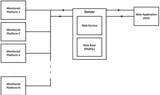
By having a top-down approach to the problem domain, one can determine that all the appli-cations developed using the framework will have the architecture shown on figure 2.3 in the top level. The architectures of the framework components will be shown further ahead.
Even though applications developed using the framework consist of three main components7,
the framework only focuses on the monitoring part of the application. This means that
applica-tions developed using the framework will only address the user interface, the server components8
and the interface between the platform and the server, leaving the platform software that will control and retrieve data from the platform to be implemented by the developer. The interface between the server and the platform implemented by the framework will impose constraints on the application developer, creating the need of respecting the communication constraints imposed by the rest of the system. These constraints include the communication protocols between the platform interface and the ”language” the system defines for communication.
7User interface, Server and monitored platform 8
Figure 2.3: Top view of the framework architecture
Since the framework will be composed by three distinct components, to ease the development process as well as the usage process of the framework, every component represents a specialization
level of the SPL that will be designed and implemented separately, meaning that the SPL is
composed by three distinct feature models, one for the server, one for the user interface and another for the platform interface. The existence of three distinct feature models creates the
problem of lack of consistency between them when instantiating the SPL, features chosen for the
server may not correspond to the features chosen for the user interface, creating an impossible configuration. To avoid this, a set of feature model constraints must be defined, assuring that if a feature is selected in the user interface feature diagram, then the corresponding feature will also be selected in the server feature diagram. By doing this, consistency between subsystems is assured and all the generated applications will function as intended.
2.2.2 User Interface
The user will interact with the monitored platforms by using a Web application through a Web browser. This Web application will be developed in HTML5 and Javascript, and will use AJAX techniques for dynamic communication with the server. These are implementation constraints that must be followed.
AJAX implements a set of asynchronous communication techniques that allow the creation of very powerful Web applications with improved functionality of what has been seen until this point. Web sites are no longer static and require a large amount of data transaction between the client and the server and if these transactions are not made asynchronously there will be a huge performance loss, because the site will always wait for an answer from the server to continue its operations. The usage of asynchronous techniques allows the site to carry other tasks while it waits for an answer, improving performance and usability. Figure 2.4 shows the block diagram of the Web application. As it can be noted, the Web application is divided into two distinct subcomponents that transact data between them, the communication back-end, responsible for Web communication with the Server, and the User Interface front-end that has direct interaction with the user.
Figure 2.4: Web application block diagram
Since all the communication with the server is done using the Web, the communication back-end does not have a great degree of variation. In this part of the system the greatest variation is on the data that is transmitted, but that is architecture independent because there is no data analysis on this stage.
The User Interface front-end interacts directly with the user. Different applications mean different interfaces, the degree of variation in the implemented pages is not huge but applications may seem completely different form each other visually after completed, due to the usage of differ-ent visual compondiffer-ents. The User Interface has a structure composed by many differdiffer-ent windows with different purposes, such as a management window, a history window or a troubleshoot win-dow. Every window has visual elements such as images, text, buttons or even multimedia content,
these elements differ both in type and format as in number. One window my have three images and a text box and another may have only one image but have a video and a list.
This makes the task of dividing the user interface into features simple, since each windows can be represented as a feature from the user interface. Each window also has different sub features, selected depending on the tasks that must be carried by a window. The following list defines the windows that can be selected and their function:
1. Login window User authentication prompt
2. Not Allowed window The user is redirected to it when it has insufficient access privileges for a given window
3. Home window This window is the user interface lobby, where the user can select which window he wants to use
4. Troubleshoot window Where the user can receive and analyse alerts and send actions to a platform
5. Management window Used to manage the several components of a system (e.g. users,
platforms)
6. History window Used to show system logs. This window shows what happened in the system and when it happened
To access the application the user must input his access credentials. This means that the access will be limited to authorized users, and it also means that users can have distinct access privileges, which means that specific actions are only available to those who have access to it. In other words, one can only access an User Interface resource if he has permission to do so. For example, a technician can access error windows and do troubleshooting but the system ad-ministrator can access these windows but can also access the management window and manage users and platforms. By imposing user privilege levels, and since the only way to affect platform operation is through the User Interface, the system guarantees that only authorized users can operate specific resources, the chance of human error by under-qualified staff.
Even though theSPLimplements a user interface based on the web, the application developer is free to implement a user interface as a native application running on a computer system. This
is possible because the interface between user interface and server is made using REST which
uses HTTP methods to establish communication. Therefore, if there are libraries that make
HTTP communication possible for a given programming language (e.g. libCurl for C or
cpp-netlib for C++), as long as the constraints imposed by the server are respected9, the developer
can implement a user interface for a given computer system and use it instead of using the one generated by the framework.
Since each application will have a distinct user interface, there are variation spots and com-monalities that have to be identified in order to establish what are the common and variable aspects between the user interfaces that are able to be generated by the framework.
The base of each user interface is common and is composed by a login page, a home page and a troubleshooting page. These pages will be a part of every user interface and match the basic requisites of the domain, providing the most basic way a user has to monitor platforms, consisting only on accessing alerts sent by a platform and the taking of actions in case of need.
Along with these common, and mandatory, aspects there are also other aspects that can be added to implement a more complete interface that depend mostly on the specific problem require-ments. These aspects vary from system to system and depend on a specific system requirerequire-ments. These variable aspects focus on management and logging needs that a specific system can have.
There may be systems where there is the need to manage system components, such as plat-forms, sensor or users. This creates the need for a management page that can vary it’s structure depending on what are the systems components. While a system may need to manage plat-forms and users, another system may need to manage users, platform groups, platplat-forms and the platforms sensors, creating variations points inside variation points.
Among with management, there are systems that can have as a requirement the logging of troubleshooting or management actions, thus creating another variation spot in the user interface. Inside the history page there can also be variations because what a system may need to log may not be what other system needs to log, creating variation points inside this page as well.
9namely the Web services URIsand their path parameters, the HTTPmethods used by each Web service and the return types for the Web services response
Web pages have a visual aspect, implemented inCSS. Even though the goal of this project is no to implement the final user interface, a basic interface that is usable has to be implemented, thus there are also styles to be applied to a specific user interface. These styles are different between them and are exclusive, meaning that only one can be used in a specific user interface and along with the other features chosen for it, it will distinguish the user interface from all the others in the system.
2.2.3 Server
The architecture exposed on figure 2.3 states that the server establishes the frontier between the user interface and the platform. Therefore all the data transmitted between these two sub-systems passes through the server, where it is processed and stored. Basically the server acts as a data repository from where the user interface gets data from the various components of the system and redirects actions from the user interface, where they are defined and sent, to the correct platform. Using a server establishing this frontier is not strictly crucial, since each embedded system, being a computer system, can implement a web server where it can host a web application, that could be used as the user interface for the platform and also host a database server, where data could be stored. However, this would impose too much load on the embedded systems and could affect their operation, and there would be a separate user interface for each platform, which would create the need to check each user interface at the time for problems in the platforms, imposing a usability problem that could affect user monitoring of the platforms. Also, in case there is limited connectivity with a platform, sending an action to it would be impossible, creating the need for the user to check manually if the connectivity to the platform is restored in order to send and action to it, which is not desirable since the user may end up by not addressing all the alerts sent by a platform.
By having a server establishing a proxy between the user interface and the platforms, the load imposed by the user interface, as well as all the web services running to support it, and the database, is taken off the embedded system and put in another computer system with higher resources available. Thus the embedded system only needs to monitor its data and send it, if needed to the server, saving the embedded system resources for the monitoring of the platform, which is the intended task for the embedded system. By having a single data repository, where
the data from all the platforms is stored, there is only the need to have a single user interface where all this data can be accessed, improving usability and making the monitoring performed by the user more efficient. Finally, in case the user sends an action to a platform and the connectivity is limited, the Web service responsible for action handling can check periodically if connectivity is establshed with the platform, and send the action when this happens.
When a platform issues an alert the server stores it in the database, established a ordered list of alerts that need addressing. The user interface polls the database periodically for new alerts and presents them to the user who takes action on the chosen alert. When taking action the user interface sends the action to the server, that redirects it to the correct platform and removes the alert from the database. Since all the systems in this domain will operate over the Web, there can be times when there is no Web connection between the server and the platform, in this case the action is put in a queue that periodically tries to send the action to the platform, thus assuring that an alert is answered.
The server may also provide other services to the user besides troubleshooting. Management does not affect platforms directly but allows a user to manage all the aspects related to a platform namely the sensors and actuators of a platform, if a platform is inserted in a group and even the platform details, such as ID and location. User management is also provided by the server, enabling the addition and removal of authorized users from the system and the editing of user details.
Other main service that can be provided by the server is history, that keeps a log of the
selected operations performed on the system10, if selected from in the feature model. History is
stored in the database with all the information relative to the system action and a time stamp from when it happened.
Database
The database plays a crucial role in the system. As it was exposed, almost all the actions taken upon a given system are reflected on the database. User authentication for example, allows access to only the users present in the database. Alerts are also stored in the database before being 10These operations comprise not only actions taken on platforms but also alerts issued by platforms, management and authentication
answered and actions that are being taken are also stored in the database if there is no connection to the platform. Information about platforms and their components are also stored in the database and in case there is the need to keep a log, it is kept in the database as well. Therefore, it can be said that the database describes a monitoring system and the relation between the system components.
By analysing the problem domain, there are some tables that can be identified as common to all the systems and others that may not be present if not needed. Every system has users, therefore, there must be a users table specifying a user details. Since every user must be authenticated to have access to the user interface, there must also be a session table, where a session ID and the corresponding user are kept.
Like users, every system also has platforms, therefore there must also be a table describing these platforms. Every platform is connected to the Web, thus having web details, stored in another table. A platform has sensors and actuators, thus there is the need for platforms also describing both sensors and actuators. These sensors and actuators may be grouped in sensor and actuator bays, depending on function of the platform, thus there must also be tables describing these bays. At last, platforms may also be grouped and thus, if this is the case, there may also be a table describing the platform groups.
Platforms issue alerts, receive actions and must also ”speak the same language” as the user, therefore there must be tables defining the alerts and the actions that can be transacted between the user and the platform, as well as a table that implements the alert queue and another that implements the action queue, in case there is no connection to the platform.
If there is the need to keep an history, there must also be tables to store this information. These tables describe the history of alerts emitted by the platforms, actions taken, user authentication and on the management of platforms and their components.
The previous paragraphs state which tables can compose the database of any given system developed using the framework. However there are some systems that are more complex than others, and therefore the tables may not always be all necessary. The most basic system must have the users, session, platform, platform web, action, current action, alert and current alerts tables in order to function properly, these tables are common to all the systems. Other tables may be added depending on the needs of a more complex system.
At this point, all the possible tables in the database are defined, but a specific system may not implement a full database as it was described. All these systems have platforms, users, alerts, actions, sensors, and actuators. But not all implement platform groups sensor and actuator bays, and may even not need to keep an history, varying with what a specific system needs. When this is the case, the tables present in the database will correspond to the system components, thus making the database of a specific system different from the database of other specific system created using this framework.
The chosen server was the MySQL community server because it is open-source and free, it is enough for what this domain needs and has a large user base that embodies a large community that gives support to the server. Also, since it is developed by Oracle, that is one of the biggest
database providers in the world11, it provides a solid solution for this framework needs. The
MySQL community server is also supported by Java, providing an easy API for accessing the
database, and establishing the connection between Java code and the database via a connector that abstracts the programmer from the complexities of the database connection.
Web Service
Data will be transmitted between all the components, but the server establishes a frontier between the platform and the user interface. Since the framework only implements the platform interface with the web service, the platform application is now a black box with a set of sensors and actuators and a defined communication method.
When communicating with a Web service, a client (platform or user interface) sends a request
to a specific URI12, thus addressing a specific web service, with a specific function. After the Web
service action is performed, a response is sent back to the client with the operation result. Data sent from platforms and user interface to the server depends on its origin. A platform sends alerts with details about the origin of the alert, that can be an error or simple information regarding the platform, to the Web service. The user interface, however, can send different types of requests to the Web services. It can be a request on a management action, where it specifies the
11
The Oracle RDBMS is widely used in key market segments such as banking and healthcare with proven reliability since 1978.
12A URI is different from a URL. The URI only defines the address where to send requests, the URL is composed by the URI and the arguments sent to the server. (e.g www.myuri.com = URI; www.myuri.com?myarguments = URL
the action to be taken and the data that corresponds to it, it can be an authentication request to grant access to a user or it can be an action sending request so that the Web service can redirect
it to the platform, among other requests. The Web services responds to all the requests in XML
format, with each response depending on what was the request. Responses can vary from OK, stating that the request associated actions were carried out successfully, to a list of unanswered alerts or users registered in the system. In case there is an error while processing a request, the Web services answer with the exception code.
In order to be able to send an action, received from the user interface, to a platform without a request from the platform, the web service establishes socket communication with the platform and sends the action code to it. Upon receiving the code, the platform applies it in order to solve whatever issue it is destined for.
Every system in the domain must have at least a set of Web services that establish commu-nication between a platform and the user, a Web service to receive alerts and another to send actions to the platform, establishing a communication channel with the user.
Authentication is also mandatory in every system, therefore there must be a Web service responsible for logging in a user, another for logging out and lastly, since the access to user interface pages is made based on privileges, there must also be a service to retrieve a given user privilege from the database and pass it to the user interface.
The previous Web services are common to all the applications in the domain providing user authentication in the system and a communication channel between the platforms and the user interface. However, more complex applications may also have the need to implement management options and even to keep an history of what has happened in the system. Therefore, a system may also have a set of Web services responsible for managing system components and another set of Web services that keep an history from all the actions taken upon the system.
By now, it is noticeable that there is a close relation between the Web services and the features selected for the user interface. This happens because the Web services process all the data displayed by the user interface and the user interface addresses a given Web service directly when requesting data from the server.
Web service architecture is based on a 3 tier architecture, shown on figure 2.5, composed of three distinct layers, each with a specific function. This architecture is used to make code
editing easier, since it logically separates the service layer, responsible for the interface with the user interface, from the business layer, where data is processed, which is also separated from the data layer, which makes the interface with the database. This favours code edition and reuse by allowing localized changes in specific parts without affecting the rest of the code and by defining the code for the different layers in different libraries, which makes it possible to port it to other projects.
Figure 2.5: Web service block diagram
The set of Web services varies from application to application. The basic set assures the basic functions carried out by the user in the user interface, therefore each application will have an authentication service to assure user authentication, and alert and action dealing web services to provide the ability to troubleshoot problems.
To establish Web service communication with the database there is a DAO layer. This layer
implements features that are common to all the systems, such as access to user, platform, action and alert tables, that provide troubleshooting and authentication access to the database. However,
depending on what are a specific system needs this layer can also implement other features, such as sensor and actuator access to the database, varying from system to system depending on what a specific system needs.
Model features exist to map database tables content in the Web services so that it can be used.
These models depend on theDAOlayer and its features have the sameDAOlayer features variation
and commonalities, varying where the DAOfeatures vary, depending on system requirements.
In case there is the need to manage system components, there are also management features that implement management web services and vary from system to system. These features are related to the management features in the user interface and vary in the same way. These are the features that grant data processing and database access for management in the user interface, providing the data that will be shown to the user in the user interface.
Like management features, there can also be logging features that also correspond to the
history features in the user interface. These features have the same variation points as the
correspondent features in the user interface and grant data processing and database access for logging related tasks in the user interface.
Finally there are features that can be useful for a system to have, depending on its needs. These features are not strictly necessary for system functioning but can improve the way some tasks are carried in a system.
2.2.4 Monitored Platform
The final sub-system of the system is the monitored platform. A specific application might be composed by several platforms, however all the platforms will run the same code to perform monitoring actions and can be described as the same. A platform has a unique identification that
is done at least by the IP address, but it can also be identified by an ID code assigned by the
system.
Platform monitoring consists on sending sensor data to the Web service via HTTP, that will
send it to the proper recipient and on receiving actions, through a socket, from the user to implement via the platforms actuators. Figure 2.6 gives a better insight on a possible architecture of the monitoring program running on a platform.
Figure 2.6: Monitored platform block diagram
Each platform has sensors and actuators that carry out troubleshooting actions at the platform level.
A sensor is the device that converts a physical parameter related to the system (e.g. temper-ature, proximity, acceleration, humidity, etc) and converts it into an electrical signal that can be measured by the embedded system performing the monitoring. Sensors have a set of parameters that determine their functioning and that assure their correct functioning under pre determined conditions.
• Accuracy Determining how accurate a read value is and how much it can deviate from the real value.
• Environmental conditions Limiting the usage in certain physical conditions, such as tem-perature and humidity, than can influence the measured values.
• Range Measured limit of the sensor, outside of which it can’t read. • Calibration In order to adapt the sensor readings to the environment. • Resolution Smallest increment in the read value detected by the sensor. • Repeatability Repeated measurement of a reading under a given environment.
On the other hand, while a sensor reads values related to the physical environment, an actu-ator acts upon the surrounding environment by transforming an electric signal into motion (e.g. activating a fan when temperature is too high). Actuator action depends on the values read by the sensor in order to establish control of the system. The parameters that define actuators are performance metrics and define how an actuator will operate under certain circumstances.
• Force Force applied by the actuator on a load. It is measured in dynamic and static loads, where the dynamic load is the actuator force capability while in motion and the static load is the force capability while the actuator is stopped.
• Speed Maximum speed at which the actuator can create motion. Its maximum value is when there is no load attached to the actuator and it decreases invariably as the load increases. • Operating Conditions Operation conditions under which an actuator can operate.
• Durability Amount of time that an actuator can function properly under certain usage and actuator quality conditions.
• Energy Efficiency Amount of energy spent by the actuator to carry on a task correctly in a certain time interval. A lower energy spending level in a fixed amount of time means that the actuator is more efficient.
Each sensor and actuator have an ID code and a type associated. This allows the user
to monitor not only the platform as a whole, but to monitor at a sensor and actuator level, increasing the granularity, making it possible to detect and correct specific problems, since failure
is not always general, but can be in a specific part of the device. The sensor bay is responsible for reading sensor data periodically and to send it, a suitable approach would be to read the sensors sequentially after a given time interval and send their data sequentially. Analogically, the actuator bay receives actions that must be carried by a given actuator and applies commands to the actuator to carry it. These are the main sensor actions, but there are other operations that can be performed on both sensors and actuators, like requesting the current status of the sensor or actuator.
Even though an explanation on a platform architecture is presented in this subsection, theSPL
will only implement the interface between the platform and the server. The application developer is responsible for developing the monitoring application running in the platform, having the freedom to implement the application in the most suitable language for the problem and with the features he desires. However, the system treats a platform as a black box able to receive and send data, this imposes a problem in case of the occurrence of a critical error or if there is no connection between the platform and the server. Thus, in case of critical error the application must be able to take preliminary action (e.g. Halt, Wait) on the platform while waiting from user input. Also, after issuing an alert on a smaller error a platform must enable a timer and wait for an action, if the action is not received in that amount of time, then the platform must halt, resuming operation when the action is received, this will prevent that a small error creates a bigger error due to the lack of correction.
By following these recommendations the developer will assure the correct functioning of the system.
Even though the platform is a black box, theSPL must define it to aid in the understanding
of the SPL architecture, since the features for the rest of the system depend on the platform
components. Therefore a platform interacts with the server by sending alerts and receiving actions, this is common to all the possible platforms within this domain. Then a platform has elements that are used to specify its structure. Thus each platform has an ID in the system, and can have other aspects such as sensors and actuators, but also bay of sensors and actuators, these features vary from system to system.
The last commonality between platforms is that each platform runs on an embedded system that can runs an operating system. This operating system is not the same to all the platforms


![Figure 3.2: Composition of two Java methods in FeatureHouse[3]](https://thumb-eu.123doks.com/thumbv2/123dok_br/17593871.819744/63.892.273.645.659.953/figure-composition-java-methods-featurehouse.webp)


